WARNING:
•Risk of electric shock
• Use extreme caution to avoid electrical shock. Serious injury or death could result.
• Always disconnect power from the safety system (for example, device, module, interfacing, etc.),
guarded machine, and/or the machine being controlled before making any connections or
replacing any component. Lockout/tagout procedures might be required. Refer to OSHA
29CFR1910.147, ANSI Z244-1, or the applicable standard for controlling hazardous energy.
• Make no more connections to the device or system than are described in this manual. Electrical
installation and wiring must be made by a Qualified Person2and must comply with the applicable
electrical standards and wiring codes, such as the NEC (National Electrical Code), ANSI NFPA79,
or IEC 60204-1, and all applicable local standards and codes.
2.3 Output Signal Switching Devices (OSSDs) and External Device
Monitoring (EDM)
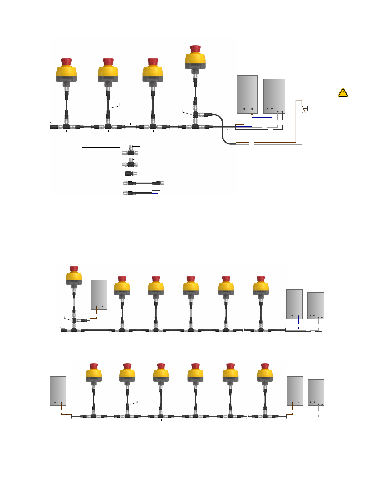
The SSA-EB1PLx-0Dx is able to detect faults on OSSD1 and OSSD2. These faults include short circuits to +24 V DC and 0
V, and between OSSD1 and OSSD2.
Both OSSD outputs must be connected to the machine control so that the machine's safety-related control system
interrupts the circuit or power to the machine primary control element(s) (MPCE), resulting in a non-hazardous condition.
Final switching devices (FSDs) typically accomplish this when the OSSDs go to an OFF state.
Refer to the output specifications and these warnings before making OSSD output connections and interfacing the SSA-
EB1PLx-0Dx to the machine.
WARNING:
•Interfacing both output signal switching devices (OSSD)
• Failure to follow these instructions could result in serious injury or death.
• Unless the same degree of safety is maintained, never wire an intermediate device(s) (PLC, PES,
PC) between the safety module outputs and the master stop control element it switches such
that a failure causes a loss of the safety stop command or the failure allows the safety function to
be suspended, overridden, or defeated.
• Connect both OSSD outputs to the machine control so that the machine’s safety-related control
system interrupts the circuit to the machine primary control element(s), resulting in a non-
hazardous condition.
WARNING:
•Interfacing OSSD Outputs to Machine Inputs
• Failure to properly interface the OSSD Outputs to the guarded machine could result in serious
injury or death.
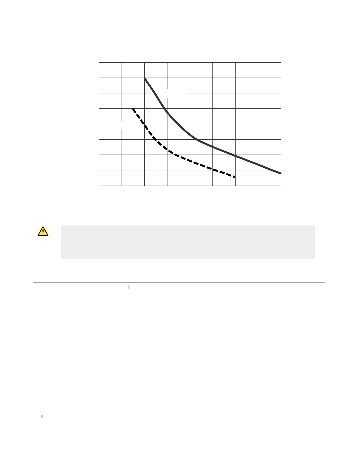
• To ensure proper operation, the Banner device output parameters and machine input parameters
must be considered when interfacing the Banner device OSSD outputs to machine inputs. Design
the machine control circuitry so that the maximum load resistance value is not exceeded and the
maximum specified OSSD Off-state voltage does not result in an On condition.
External device monitoring (EDM) is a function used to monitor the state of the external, positively guided (mechanically
linked) machine control contacts (Final Switching Devives (FSD) and/or MPCEs). The SSA-EB1PLx-0Dx does not include the
EDM function. As a result, the SSA-EB1PLx-0Dx should be used with an external safety monitoring device that monitors the
status of the two SSA-EB1PLx-0Dx OSSDs and is capable of providing the EDM function.
Examples of appropriate external safety monitoring devices include the Banner SC10-2ro Safety Controller.
WARNING:
•The SSA-EB1PLx-0Dx does not have external device monitoring (EDM).
• If EDM is required for the application, it must be implemented in the external control.
2A person who, by possession of a recognized degree or certificate of professional training, or who, by extensive knowledge, training and
experience, has successfully demonstrated the ability to solve problems relating to the subject matter and work.
SSA-EB1PLx-0Dx Series Lighted Emergency Stop Button with ISD
6 www.bannerengineering.com - Tel: + 1 888 373 6767