Bannon 55829 User manual

READ & SAVE THESE INSTRUCTIONS
5500-Lb. Capacity Multi-Directional
Pallet Jack
Owner’s Manual
WARNING: Read carefully and understand all ASSEMBLY AND OPERATION
INSTRUCTIONS before operating. Failure to follow the safety rules and other basic safety
precautions may result in serious personal injury.
Item #55829

Page 2 of 17
Thank you very much for choosing a Bannon™product!
For future reference, please complete the owner’s record below:
Serial Number/Lot Date Code: ________________________________
Purchase Date: ____________________________________________
Save the receipt, warranty, and this manual. It is important that you read
the entire manual to become familiar with this product before you begin
using it.
This pallet jack is designed for certain applications only. Northern Tool
and Equipment is not responsible for issues arising from modification or
improper use of this product such as an application for which it was not
designed. We strongly recommend that this product not be modified
and/or used for any application other than that for which it was designed.
For technical questions, please call 1-800-222-5381.

Page 3 of 17
Table of Contents
Intended Use..........................................................................................................................................4
Packaging Contents..............................................................................................................................4
Technical Specifications......................................................................................................................4
Important Safety Information...............................................................................................................4
Specific Operation Warnings...............................................................................................................5
Assembly Instructions..........................................................................................................................6
Operating Instructions..........................................................................................................................8
Maintenance ........................................................................................................................................10
Troubleshooting..................................................................................................................................12
Parts Diagram......................................................................................................................................13
Parts List..............................................................................................................................................13
Replacement Parts..............................................................................................................................15
Limited Warranty.................................................................................................................................16

Page 4 of 17
Intended Use
The Bannon 5500 Lb. Capacity Multi-Directional Pallet Jack is designed for transportation of loads
with a level, attached base and may be used only on a firm and even surface, such as concrete or
asphalt. The load must be on evenly distributed pallets, with the ideal loading mode such that the
center of gravity of the load is at the central position of the fork.
Packaging Contents
Part A (1)
Part B (1)
Frame Assembly (1)
Handle (1)
Technical Specifications
Property
Specification
Capacity
5500 lb. (2500 kg)
Fork Length
48 in. (1220 mm)
Width
27 in. (685 mm)
Lift Range
3 –8-1/2in. (75 –190 mm)
Guide Roller Size
2 in. (51 mm)
Steering Wheel Size
7 in. (180 mm)
Important Safety Information
⚠WARNING
Read and understand all instructions. Failure to follow all instructions may result in serious injury
or property damage.
The warnings, cautions, and instructions in this manual cannot cover all possible conditions or
situations that could occur. Exercise common sense and caution when using this tool. Always be
aware of the environment and ensure that the tool is used in a safe and responsible manner.
Do not allow persons to operate or assemble the product until they have read this manual and
have developed a thorough understanding of how it works.
Do not modify this product in any way. Unauthorized modification may impair the function and/or
safety and could affect the life of the product. There are specific applications for which the product
was designed.
Use the right tool for the job. DO NOT attempt to force small equipment to do the work of larger
industrial equipment. There are certain applications for which this equipment was designed. This
product will be safer and do a better job at the capacity for which it was intended. DO NOT use
this equipment for a purpose for which it was not intended.
Industrial or commercial applications must follow OSHA requirements.
⚠WARNING

Page 5 of 17
WORK AREA SAFETY
Inspect the work area before each use. Keep work area clean, dry, free of clutter, and well-lit.
Cluttered, wet, or dark work areas can result in injury. Using the product in confined work areas
may put you dangerously close to cutting tools and rotating parts.
Do not allow the product to come into contact with an electrical source. The tool is not insulated
and contact will cause electrical shock.
Keep children and bystanders away from the work area while operating the tool. Do not allow
children to handle the product.
⚠WARNING
PERSONAL SAFETY
Stay alert, watch what you are doing, and use common sense when operating the tool. Do not use
the tool while you are tired or under the influence of drugs, alcohol, or medication. A moment of
inattention while operating the tool may result in serious personal injury.
Dress properly. Do not wear loose clothing, dangling objects, or jewelry. Keep your hair, clothing
and gloves away from moving parts. Loose clothes, jewelry, or long hair can be caught in moving
parts. Air vents on the tool often cover moving parts and should be avoided.
Wear the proper personal protective equipment when necessary. Use ANSI Z87.1 compliant safety
goggles (not safety glasses) with side shields, or when needed, a face shield. Use a dust mask in
dusty work conditions. Also use non-skid safety shoes, hardhat, gloves, dust collection systems,
and hearing protection when appropriate. This applies to all persons in the work area.
⚠CAUTION
PALLET JACK USE AND CARE
Do not force the pallet jack. Products are safer and do a better job when used in the manner for
which they are designed. Plan your work, and use the correct product for the job.
Check for damaged parts before each use. Carefully check that the product will operate properly
and perform its intended function. Replace damaged or worn parts immediately. Never operate the
product with a damaged part.
Store the product when it is not in use. Store it in a dry, secure place out of the reach of children.
Inspect the tool for good working condition prior to storage and before re-use.
Keep guards in place and in working order. Never operate the product without the guards in place.
Specific Operation Warnings
⚠WARNING
Do not exceed the rated load capacity.
Be sure the load is secure and stable before moving.

Page 6 of 17
Do not operate a loaded pallet jack on ramps or inclines.
Keep the load centered on the pallet jack.
Wear steel toed boots while operating the pallet jack.
Check for damaged parts before operating. Do not operate a damaged or faulty pallet jack. Do not
attempt repairs unless you are trained or authorized to do so.
Operate a pallet jack from a designated operating position. Keep hands, feet, and other body parts
clear from the lifting mechanism and under the forks of the pallet jack.
Do not use to transport people or animals.
Be sure the load is stable and secure before moving.
Be sure to evenly distribute the load before moving.
Be sure the length of the forks match the length of the pallet.
Lower the forks to the lowest height when the pallet jack is not in use.
For use on a hard, level surface. Do not use on a grade or angled surface.
Do not use if the operator is not physically capable of safely operating with a full load.
When lifting a pallet jack, the hydraulics may retract the wheels into the frame of the forks,
crushing fingers, feet, and other body parts.
Do not place your hands on the side of the pallet jack while lifting. Always use the end of the forks
for lifting.
Assembly Instructions
Tools Required for Assembly
Hammer
Flat Head Screwdriver
Pliers

Page 7 of 17
1. Insert the base of the handle into the pump bracket (Figure 1). Align the holes at the base of
the handle with the holes in the pump bracket.
2. Use a hammer to tap the handle pin into the holes of the pump bracket and handle (Figure 2).
Use pliers to turn the handle pin until its holes align with the spring pin holes.
3. Feed the screw head through the center hole in the handle pin (Figure 3). Using a screwdriver,
pry up the cam and slip the screw head under the notch in the cam.

Page 8 of 17
4. Use a hammer to tap the spring pins (Figure 2) into the holes on the pump bracket and
handle pin.
5. Tap out the pump retainer pin (Figure 1).
NOTE: It is a good idea to remove any air bubbles that might have accumulated in the hydraulic
system during shipping. Refer to “BLEEDING THE AIR” in the maintenance section.
Operating Instructions
⚠WARNING
To avoid serious bodily injury or death, and/or property damage, do not exceed the rated load
capacity.
When not in use, do not allow heavy loads to remain on the fork for an extended period of time.
Always lower the fork completely when not in use.
This pallet truck is designed for use with open style pallets or skids only. Closed style pallets must be
placed on top of fork prior to use.
1. Insert the fork into the pallet.
2. To raise the fork, push control lever all the way down, and pump the handle until the desired fork
height is reached.
3. To move the handle without affecting the fork setting, set the control lever in the center neutral
position. The load can now be pushed or pulled using the handle.
4. To lower the fork, pull lever all the way up. Allow the load to descend slowly in a controlled
manner. The lever is spring-loaded and will return to the neutral position when released.
NOTE: Numbers in parentheses refer to part numbers in the breakdown.

Page 9 of 17
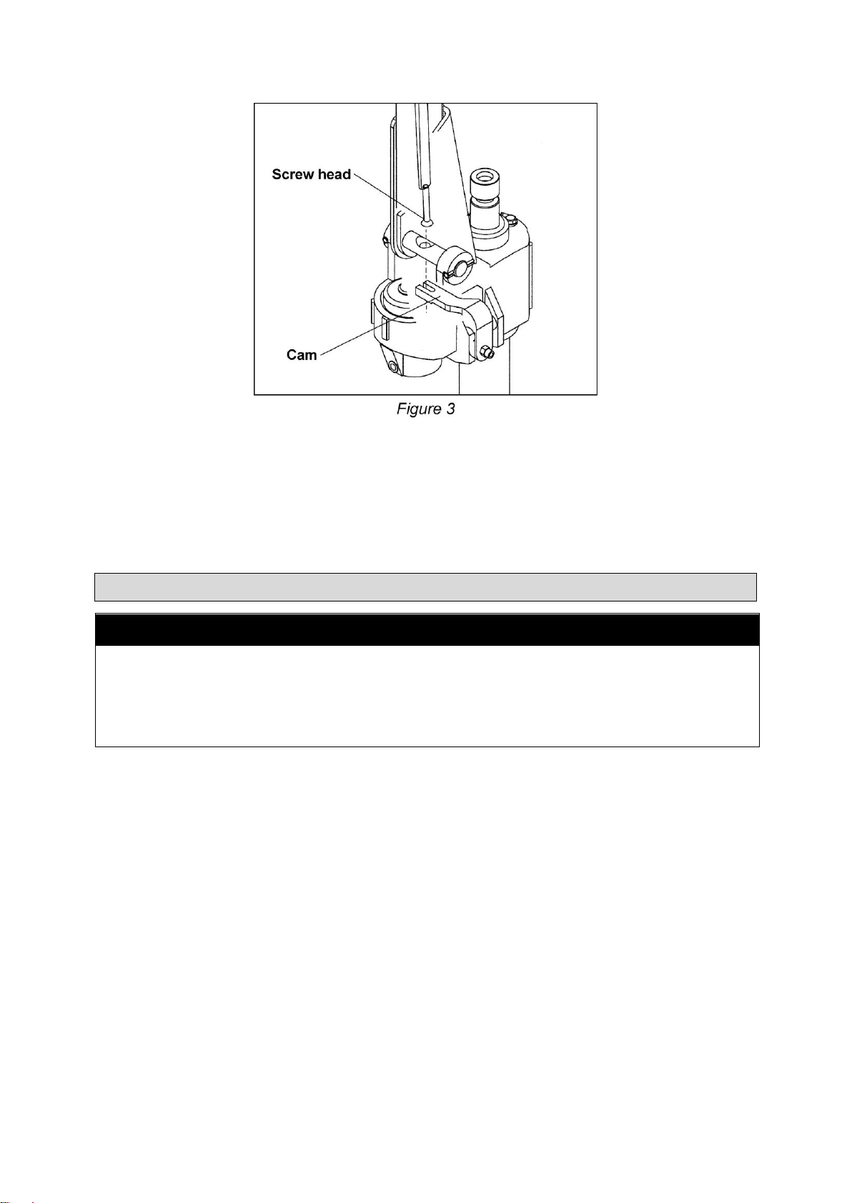
Adjusting the Control Handle - 3 Positions
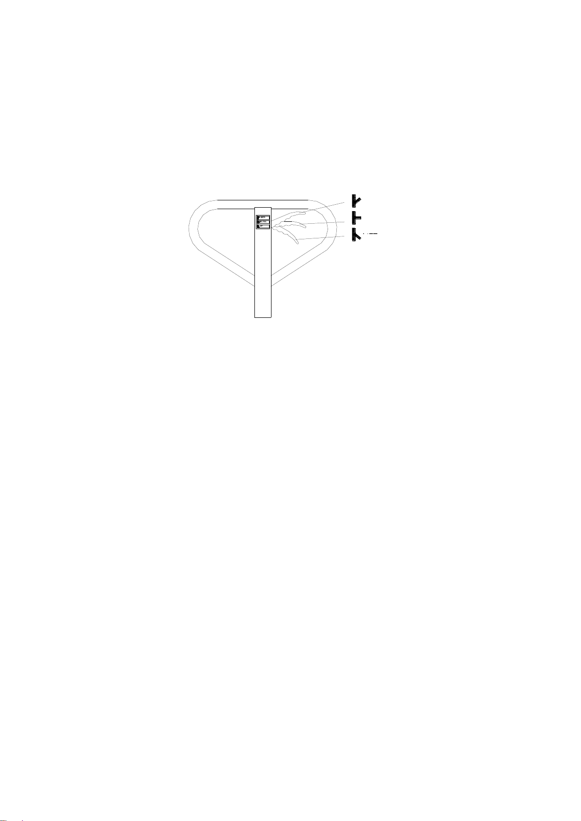
On the Handle (1) of this pallet jack, you can find the Control Lever (7), which can be placed in three
positions (See Figure 4):
LOWER - to lower the load, pull up on the control lever.
NEUTRAL - to place the control lever in this position while pulling the pallet jack or load.
LIFT - to raise the load, push down on the control lever and pump the handle to raise the load.
Figure 4
NOTE: These three positions have been set at the factory to work appropriately as soon as the
handle is attached. However, if the forks do not raise or lower as expected, adjust the control
positions using the following instructions. See Figure 5 on the following page.
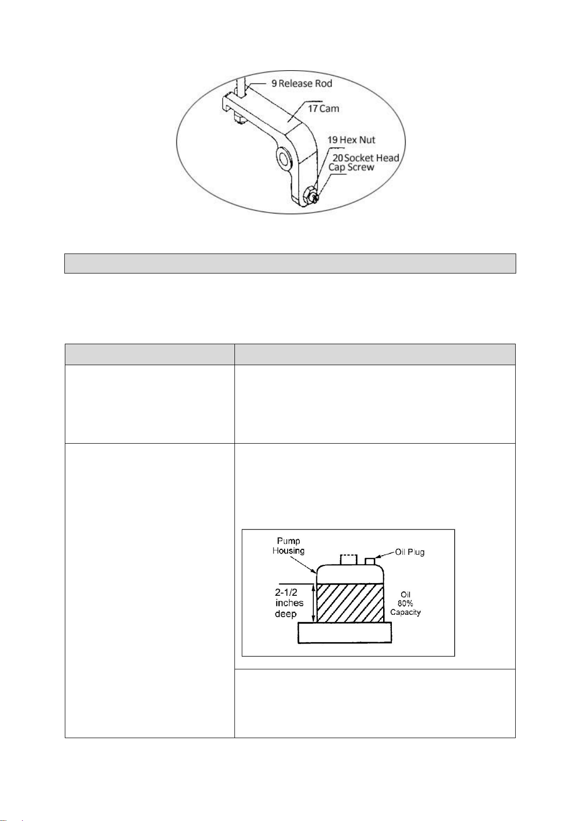
1. The Socket Head Cap Screw (20) is designed to adjust the three control positions. Use a
wrench and a flat screwdriver to loosen the Hex Nut (19) and turn the Socket Head Cap
Screw (20) clockwise, or counter-clockwise. Check to see if the pallet jack works well in the
three control positions. If more adjustments are necessary, proceed to the following steps.
2. Place the control handle in the "NEUTRAL" position. If the fork frame does not rise when
you pump the pallet jack, skip to step 5. If the fork frame does rise when you pump the
truck, turn the Socket Head Cap Screw (20) CLOCKWISE until the fork frame does not rise.
3. Keep the control handle in "NEUTRAL" position. If the fork frame does not move when the
handle is pumped, skip to step 4 without any adjustment. If the fork frame lowers, turn the
Socket Head Cap Screw (20) COUNTER-CLOCKWISE until the fork frame does not lower.
4. Pull the Control Lever (7) upward to the "LOWER" position. If the fork frame lowers, skip to
step 5 without any adjustment. If the fork frame does not lower, turn the Socket Head Cap
Screw (20) CLOCKWISE again until the fork frame lowers.
5. Push the Control Lever (7) down to the "LIFT" position. If the fork frame elevates when you
pump the pallet jack, go back to step 1 to 3 until the pallet jack can work well in all three
control positions. If the fork frame does not elevate, turn the Socket Head Cap Screw (20)
COUNTER-CLOCKWISE again until the fork frame elevates. Repeat steps 1 through 3 until
the pallet jack works in all three control positions.
Lower
Neutral
Lift

Page 10 of 17
Figure 5
Maintenance
Maintain the product by adopting a program of conscientious repair and maintenance in accordance
with the following recommended procedures. It is recommended that the general condition of any tool
be examined before it is used. Keep handles dry, clean, and free from oil and grease. The following
chart is based on a normal operation schedule.
Maintenance Interval
Maintenance Point
Daily before operating
Daily inspection and maintenance of the pallet truck is
required, especially for the wheels and the axles. Remove
thread or rags on the wheel or axle if any is detected. Unload
and lower the forks to the lowest position after every job is
finished.
Before and after operating
OIL. Check the oil level annually by removing the oil plug (58)
on top of the pump housing. When changing or adding oil, fill
the tank through the oil plug hole to 80% capacity with
hydraulic jack oil, about 2-1/2” deep in pump housing. See
Figure 6. Do not use any other type of oil. When finished,
replace the oil plug (58).
Fig. 6
LUBRICATION. Wheel bearings are sealed and require no
lubrication. The crankshaft features “oil lite” bushings that also
require no lubrication.
Lightly oil all other moving parts.

Page 11 of 17
Maintenance Interval
Maintenance Point
BLEEDING THE AIR. There may be times when the forks do
not rise while pumping when in the "LIFT" position. Most likely
this is because air has been introduced in to the hydraulic
system. The air can be removed by moving the control handle
to the "LOWER" position, then pumping the handle up and
down several times. Repeat this process until the forks lift as
intended.
SEAL AND O-RING REPLACEMENT FOR RAM AND
PLUNGER PISTON
Raise the pallet jack by pumping the handle.
Remove the spring pin (26). This will free the pump and
handle assembly from the pallet jack.
Remove the oil plug (58), turn pump over and empty the
oil into a suitable container. Pump the handle until all the
oil has drained. Dispose of the used hydraulic oil
according to local disposal regulations.
Pull out the plunger piston 64) and/or ram piston (60).
Remove all O-rings and seals. See Fig. 7.
Insert a new O-ring or seal one at a time making sure to
replace with the same size that was removed.
Reassemble and fill the oil tank through the oil plug hole to
80% capacity with new hydraulic jack oil, about 2-1/2”
deep in pump housing. See Fig. 6.
Fig.7
UP-DOWN CAM ADJUSTMENT
When pumping the handle with the lever in the neutral
position, there should be no movement of the fork. If there is
fork movement, the cam must be adjusted:
Place the lever in the neutral position.
Loosen the hex nut (19).
Adjust the socket head cap screw (20) while pumping
the handle, until there is no longer any movement of
the ram.
Tighten the hex nut (19).

Page 12 of 17
Troubleshooting
Failure
Possible Cause
Corrective Action
Hydraulic unit
does not lift
Low oil level.
Make sure there is no oil leakage from
Release Screw (35), Pressure
Adjustment Screw (33) or valve area.
Then add oil.
Air in pump.
See ''BLEEDING THE AIR''.
Worn O-ring in ram cylinder.
Replace O-ring (refer to ''Seal and O-
Ring Replacement'').
Once lifted, truck
lowers by itself
Air comes into the oil.
See ''BLEEDING THE AIR''.
Worn O-ring in ram cylinder.
Replace O-ring (refer to ''Seal and O-
Ring Replacement'').
Release valve not seated properly.
See ''BLEEDING THE AIR''.
Pallet truck loaded beyond capacity.
Reduce load to within capacity.
Release valve not adjusted properly.
Adjust valve by Pressure Adjustment
Screw (33) and Release Screw (35).
Oil leakage from Release Screw (38) or
Pressure Adjustment Screw (40).
Tighten Release Screw (35). Replace
O-rings on Release Screw (35) and/or
Pressure Adjustment Screw (33). If
leakage continues, contact authorized
service center.
Fork does not
lower
Cam requires adjustment.
Refer to ''Up-Down Cam Adjustment''.
Cam (14) is damaged.
Replace Cam (17).
Damaged push rods and/or linkages.
Replace damaged parts. (It is
recommended that an authorized
service center perform this work.)
Lever does not
stay in the
neutral position
Cam requires adjustment.
Refer to ''Up-Down Cam Adjustment''.

Page 13 of 17
Parts Diagram
Parts List
Reference
Part Number
Part Description
Qty.
Remark
1
1
Handle
1
2
2
Spring Pin
2
3
3
Blade Spring
1
4
4
Spring Pin
1
5
5
Roller
1
6
6
Lever Mat
1
7
7
Lever Mat
1
8
8
Spring Pin
1
9
9
Control Lever
1
10
10
Oil Lite Bushing
2
11
11
Release Rod
1
12
12
Pressure Roller
1
13
13
Spring Pin
1
14
14
Oil Lite Bushing
2
15
15
Handle Pin
1
16
16
Spring Pin
2
17
17
Cam
1
18
18
Spring Pin
1
19
19
Hex Nut
1
20
20
Socket Head Cap Screw
1
21
21
Table Pin
2
22
22
Spring Pin
2
23
23
Table
1
24
24
Snap Ring
1
25
25
Ball Bearing
1
26
26
Spring Pin
1
27
27
Pump Housing
1
28
28
Wheel Shaft
1
29
29
Ball Bearing
4
30
30
Steering Wheel
2

Page 14 of 17
Reference
Part Number
Part Description
Qty.
Remark
31
31
Snap Ring
2
32
32
Dust Seal Cap
2
33
33
Pressure Adjust Screw
1
34
34
Copper Washer
1
35
35
Release Screw
1
36
36
Spring
1
37
37
Spring Base
1
38
38
Steel Ball
1
39
39
O-Ring
1
40
40
Release Nozzle Base
1
41
41
O-Ring
1
42
42
Release Nozzle
1
43
43
Release Nozzle Spring
1
44
44
Oil Baffle Washer
1
45
45
O-Ring
1
46
46
Mid-Valve Base
1
47
47
Oil Baffle Washer
1
48
48
O-Ring
1
49
49
Steel Ball
1
50
50
Needle Valve
1
51
51
Needle Valve Spring
1
52
52
Valve Cap
1
53
53
Spring Pin
1
54
54
Limit Pin
1
55
55
Spring
1
56
56
Cap
1
57
57
O-Ring
1
58
58
Oil Plug
1
59
59
Steel Ball
1
60
60
Ram Piston
1
61
61
Dust Seal Ring
1
62
62
O-Ring
1
63
63
U-Packing
1
64
64
Plunger Piston
1
65
65
Spring Cap
1
66
66
Spring
1
67
67
Dust Seal Ring
1
68
68
U-Packing
1
69
69
Plunger Housing
1
70
70
Washer
1
71
71
Pump Retainer Pin
1
72
72
Fork Frame
1
73
73
Spring Washer
1
74
74
Socket Head Cap Screw
1
75
75
Lifting Yoke
1
76
76
Spring Pin
1
77
77
Push Rod
2
78
78
Crank Pin
2
79
79
Crank Shaft
1
80
80
Snap Ring
2
81
81
Spring Pin
2
82
82
Arm Pin
2
83
83
Washer
4
84
84
Wheel Frame
2
85
85
Wheel
2
86
86
Ball Bearing
4
87
87
Wheel Axle
2

Page 15 of 17
Reference
Part Number
Part Description
Qty.
Remark
88
88
Spring Pin
2
89
89
Oiler
4
90
90
Rod Pin
2
91
91
Spring
4
92
92
Spring Pin
2
93
93
Wheel Frame
2
94
94
V Nut
4
95
95
Screw
4
96
96
Spring Pin
2
97
97
Nog
2
98
98
Ball Bearing
4
99
99
Wheel
2
100
100
Wheel Axle
2
Replacement Parts
For replacement parts and technical questions, please call Customer Service at 1-800-222-5381.
Not all product components are available for replacement. The illustrations provided are a
convenient reference to the location and position of parts in the assembly sequence.
When ordering parts, the following information will be required: item description, item model
number, item serial number/item lot date code, and the replacement part reference number.
The distributor reserves the rights to make design changes and improvements to product lines
and manuals without notice.

Page 16 of 17
Limited Warranty
Northern Tool and Equipment Company, Inc. ("We'' or ''Us'') warrants to the original purchaser only
(''You'' or ''Your'') that the Bannon product purchased will be free from material defects in both
materials and workmanship, normal wear and tear excepted, for a period of two years from date of
purchase. The foregoing warranty is valid only if the installation and use of the product is strictly in
accordance with product instructions. There are no other warranties, express or implied, including the
warranty of merchantability or fitness for a particular purpose. If the product does not comply with this
limited warranty, Your sole and exclusive remedy is that We will, at our sole option and within a
commercially reasonable time, either replace the product or product component without charge to You
or refund the purchase price (less shipping). This limited warranty is not transferable.
Limitations on the Warranty
This limited warranty does not cover: (a) normal wear and tear; (b) damage through abuse, neglect,
misuse, or as a result of any accident or in any other manner; (c) damage from misapplication,
overloading, or improper installation; (d) improper maintenance and repair; and (e) product alteration
in any manner by anyone other than Us, with the sole exception of alterations made pursuant to
product instructions and in a workmanlike manner.
Obligations of Purchaser
You must retain Your product purchase receipt to verify date of purchase and that You are the original
purchaser. To make a warranty claim, contact Us at 1-800-222-5381, identify the product by make
and model number, and follow the claim instructions that will be provided. The product and the
purchase receipt must be provided to Us in order to process Your warranty claim. Any returned
product that is replaced or refunded by Us becomes our property. You will be responsible for return
shipping costs or costs related to Your return visit to a retail store.
Remedy Limits
Product replacement or a refund of the purchase price is Your sole remedy under this limited warranty
or any other warranty related to the product. We shall not be liable for: service or labor charges or
damage to Your property incurred in removing or replacing the product; any damages, including,
without limitation, damages to tangible personal property or personal injury, related to Your improper
use, installation, or maintenance of the product or product component; or any indirect, incidental or
consequential damages of any kind for any reason.
Assumption of Risk
You acknowledge and agree that any use of the product for any purpose other than the specified
use(s) stated in the product instructions is at Your own risk.
Governing Law
This limited warranty gives You specific legal rights, and You also may have other rights which vary
from state to state. Some states do not allow limitations or exclusions on implied warranties or
incidental or consequential damages, so the above limitations may not apply to You. This limited
warranty is governed by the laws of the State of Minnesota, without regard to rules pertaining to
conflicts of law. The state courts located in Dakota County, Minnesota shall have exclusive jurisdiction
for any disputes relating to this warranty.

Page 17 of 17
Distributed by:
Northern Tool & Equipment Company, Inc.
Burnsville, Minnesota 55306
www.northerntool.com
Made in China
Other manuals for 55829
1
Table of contents
Other Bannon Jack manuals
Popular Jack manuals by other brands

MSW
MSW MSW-TJS2-02 user manual

Pro-Lift
Pro-Lift F1800A owner's manual

Valex
Valex 1650530 Instruction manual and safety instructions

Badland
Badland 58395 Owner's manual & safety instructions

Raider
Raider RD-TJ05 Original instruction manual

BE Ag & Industrial
BE Ag & Industrial 35.310.012 Operating instructions manual