3/19
Designed for care
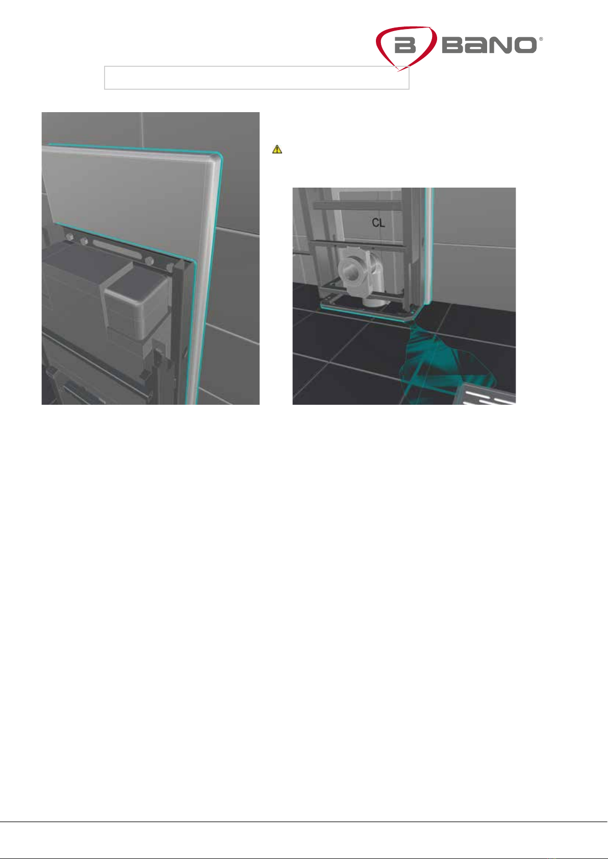
Introduction
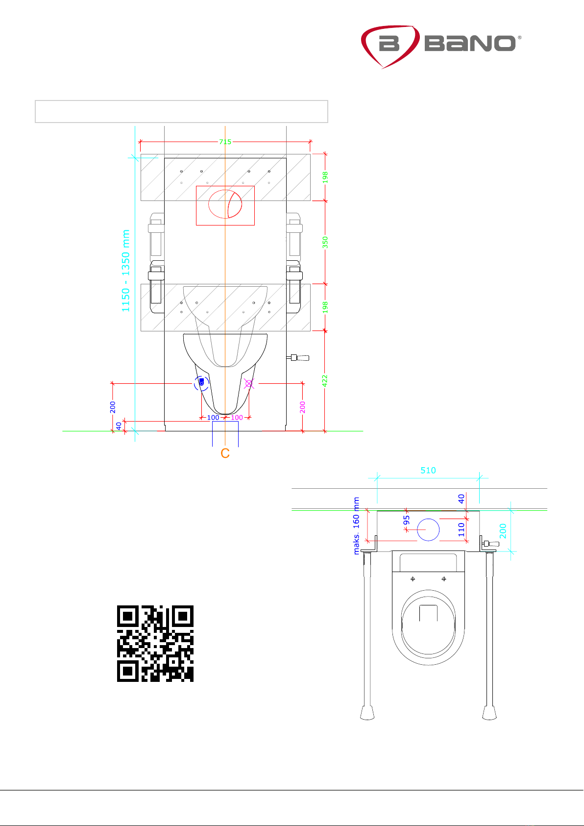
Bano’s height-adjustable cisterns can be adjusted either manually with a crank or
electrically. This lightens the carer’s work load because one person can quickly and easily
adjust the height of the toilet to t the users need. The height of the toilet can be adjusted
from 410 to 610 mm.
The cistern is supplied either with a manual hand crank or with electrical height adjustment.
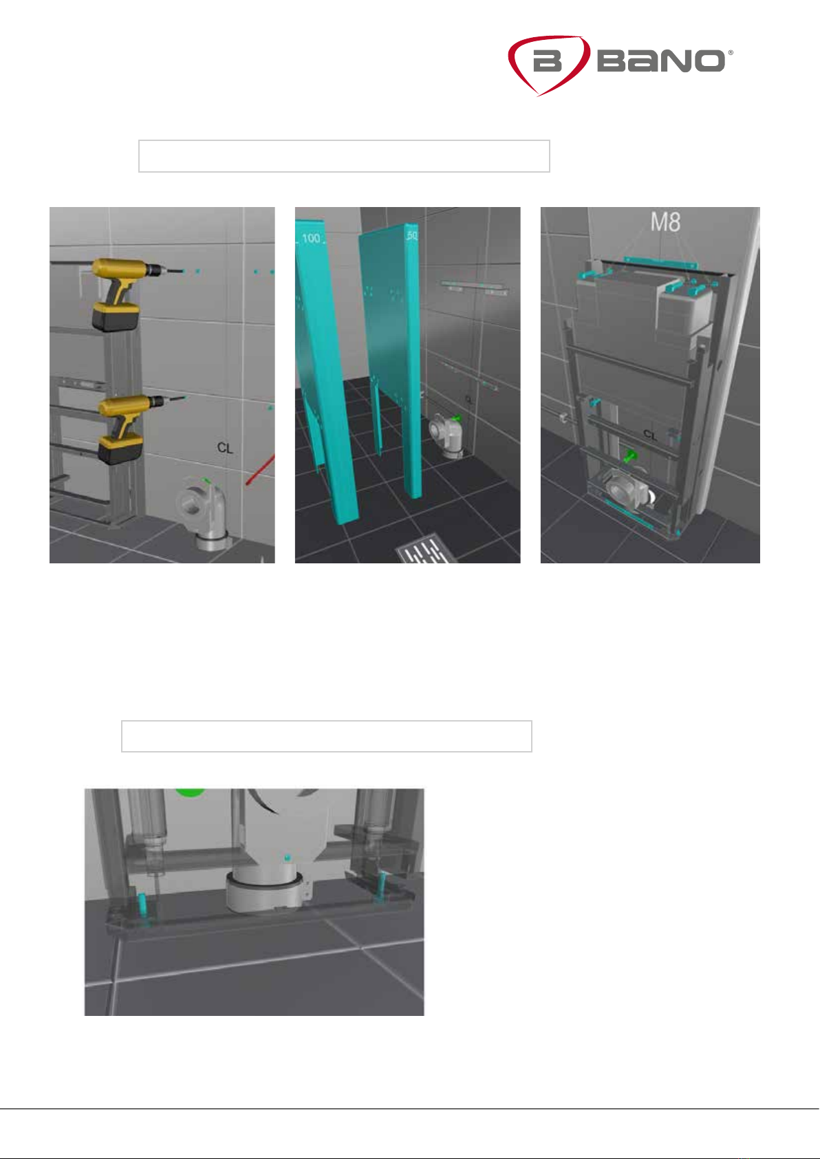
With simple steps the height of the toilet and the WC grab bars can be adjusted. For
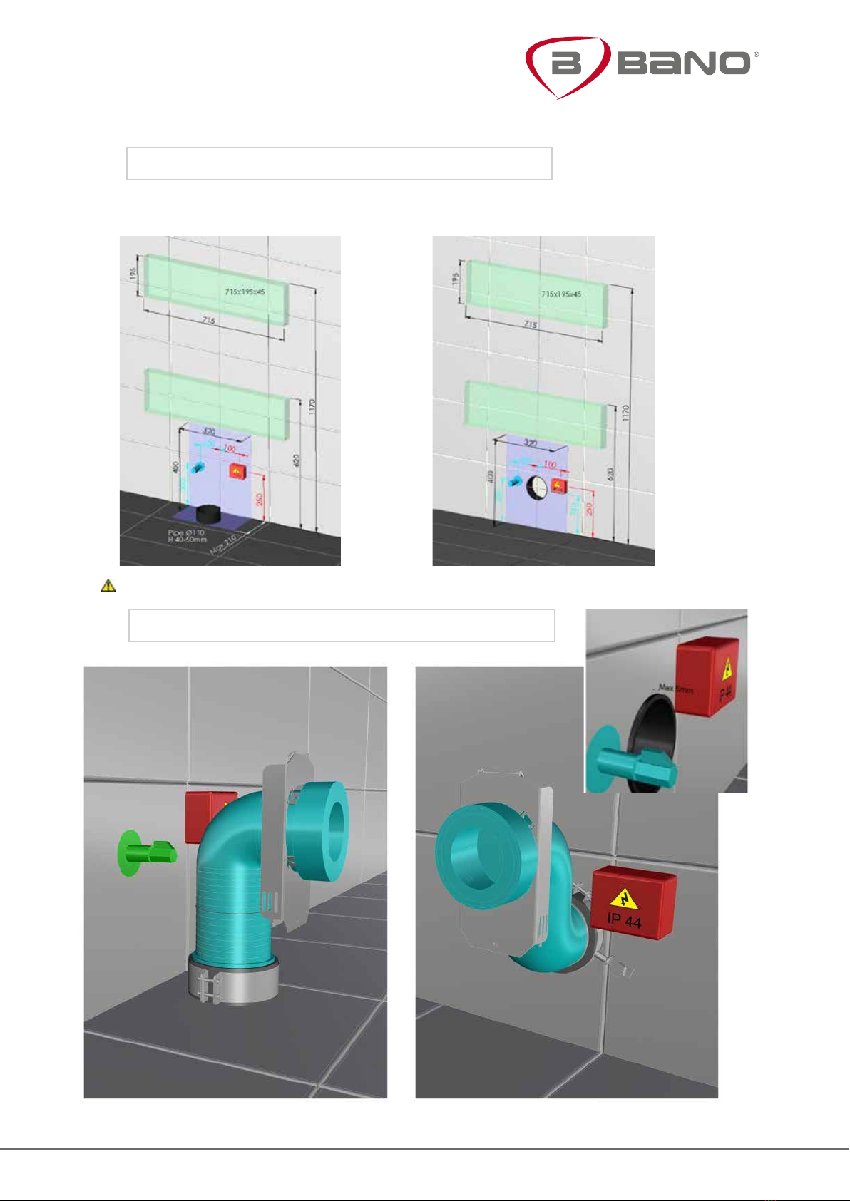
bathrooms with external pipes an extension for the cistern must be used. For more
information see Bano interface on www.bano.no
Electrical adjustment is operated by a button on the top of the cistern. For manual
adjustment, use the accompanying crank.
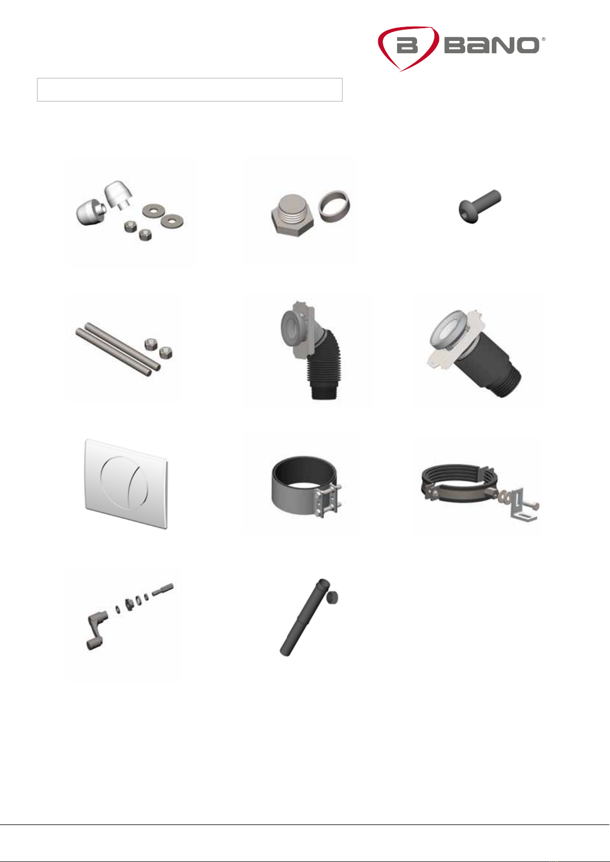
Accessories
Installed with a Bano WC 530 or a Bano WC 700 (5965/5975), and grab bars for WC/cistern
(5603/5604). With external pipes, please use an extension (5970-22/5970-23), either 50 mm
or 100 mm.
Article numbers:
5965 WC 530
5975 WC 700
5985EC WC 530 mm EasyClean
5995EC WC-bowl 700 mm EasyClean
5603 Grab bars WC 900 mm (35 in.)
5604 Grab bars WC 700 mm (28 in.)
5970-22 Extension 50 mm
5970-23 Extension 100 mm
5970-03 Toilet seat, white
5970-06 Toilet seat, grey
Compliance with the EU directive
This product is CE branded and meet the provisions in the EU safety requirements laid
down in the Medical Devices Directive 93/42/EEC, class 1.
See also:
EN 12182: 2012: Assistive products for persons with disability
EN 14055: 2011: WC and urinal ushing cisterns
EN 997: 2013: Sanatary appliances, washbasins