BAQ alphaDUR mini User manual

alphaDUR mini
Manual
Version 1.5


Contents
1 Introduction.......................................................................................................5
2 Manual.............................................................................................................. 6
2.1 Lettering.....................................................................................................6
2.2 Text boxes..................................................................................................6
3 Information on the probes................................................................................7
3.1 robe selection..........................................................................................7
3.2 robe handling...........................................................................................7
4 General working instructions............................................................................9
4.1 Key functions..............................................................................................9
4.2 Status bar.................................................................................................10
4.3 The menus...............................................................................................10
4.4 Text entry.................................................................................................10
4.5 The number field......................................................................................12
5 Measurement..................................................................................................13
5.1 Specimen requirements...........................................................................13
5.2 Measuring parameter...............................................................................14
5.3 Measuring procedure...............................................................................15
5.4 Measuring window...................................................................................15
5.4.1 Key assignment of the measuring window........................................17
5.5 Statistics...................................................................................................17
5.5.1 Display of statistics............................................................................17
5.6 Instant printout.........................................................................................19
6 Measuring parameter.....................................................................................20
6.1 Description...............................................................................................20
6.2 Managing sets of measuring parameter..................................................21
6.2.1 Editing measuring parameter............................................................21
6.2.2 Saving measuring parameter............................................................21
6.2.3 Loading measuring parameter...........................................................22
6.2.4 Deleting a set of measuring parameter.............................................22
7 Conversion of hardness values......................................................................23
7.1 Selection of the conversion standard to be used.....................................24
8 Material calibration.........................................................................................25
9 Memory functions...........................................................................................28

9.1 Creating a new series..............................................................................29
9.2 Continuing a series..................................................................................29
9.3 New serial measurements.......................................................................30
9.4 Continuing a serial measurement............................................................30
9.5 Deleting a series......................................................................................30
9.6 Displaying a series...................................................................................30
9.7 Copying of series to an USB flash drive..................................................31
9.7.1 CSV file format...................................................................................31
9.7.1.1 Single series and subordinated series of a serial measurement....31
9.7.1.2 Summary serial measurements......................................................32
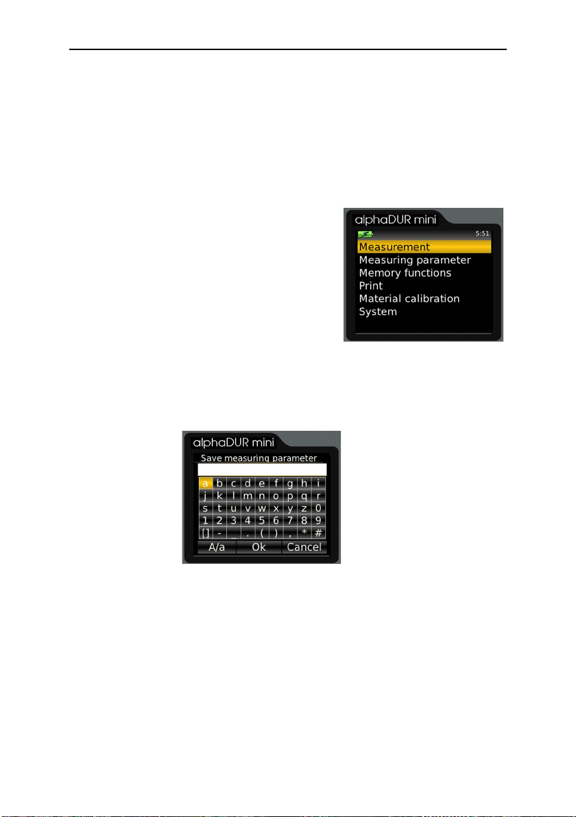
10 System settings............................................................................................34
10.1 Language...............................................................................................34
10.2 Time.......................................................................................................34
10.3 Date........................................................................................................34
10.4 Configuration..........................................................................................34
10.4.1 Date format......................................................................................34
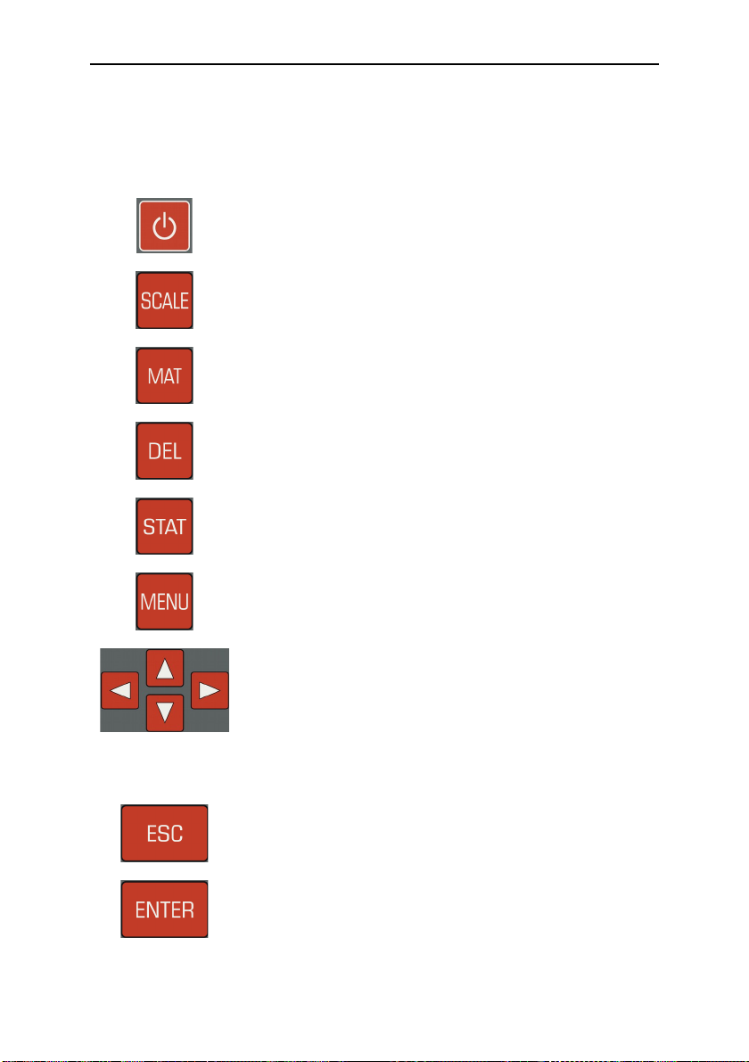
10.4.2 Key SCALE......................................................................................34
10.4.3 Key MAT..........................................................................................35
10.4.4 Query whether the values should be saved in a series...................35
10.4.5 Query whether the values should be printed...................................35
10.4.6 Tensile strength unit........................................................................35
10.5 Factory defaults.....................................................................................36
10.6 System information................................................................................36
11 Maintenance and inspection.........................................................................37
12 The UCI method...........................................................................................38
13 roper disposal............................................................................................40
13.1 Deutsch..................................................................................................40
13.2 Français.................................................................................................40
13.3 Italiano....................................................................................................40
13.4 Español..................................................................................................41
14 Technical Data..............................................................................................42
15 Appendix 1: Hardness conversion validity ranges........................................44
15.1 DIN EN ISO 18265 - Feb.2014..............................................................44
15.2 ASTM E140 - 12b (2019).......................................................................46
16 Appendix 2: License information..................................................................48

INTRODUCTION
1 Introduction
The alphaDUR mini is a portable hardness tester. Vickers hardness is
measured according to the UCI (Ultrasonic Contact Impedance) method.
The alphaDUR mini offers the opportunity to convert the measured Vickers
hardness according to DIN EN ISO 18265 or ASTM E140 to other hardness
scales.
Up to 100,000 readings including hardness, date, time and measuring
parameter can be stored to the internal memory of the alphaDUR mini.
The readings are arranged in series of measurements. A series of
measurements is an aggregation of several readings. In addition to ordinary
measurement series, serial measurement series which consists of multiple
subordinate measurement series, can be recorded. Saved series of
measurements, including statistics, can be displayed, printed or copied to a
USB flash drive at any time.
5

MANUAL
2 Manual
2.1 Lettering
Operating elements Operating elements
KEY Keys
Standard text Descriptions and explanations in text form
Important notes Important notes and remarks
2.2 Text boxes
Operating elements
Explanations of functions and operating
elements are framed in blue.
Entry fields
Green fields describe user inputs and
parameters
Information
Information and notes are provided with yellow
background
Important notes
Important notes and warnings are represented
in red boxes
6

INFORMATION ON THE ROBES
Information on the probes
.1 Probe selection
alphaDUR UCI probes are available with test loads of 10, 20, 30, 49 and 98 N.
This corresponds to the Vickers test loads HV1, HV2, HV3, HV5 and HV10 (1,
2, 3, 5 and 10 kg). Like that the optimal test load for a particular test task can
be chosen.
For rough surfaces higher test loads are
recommended to create greater
indentations. If many measurements follow
one another, tests could be difficult without
using a bench stand to apply test loads like
10 kg steadily and vertically.
.2 Probe handling
The protective sleeve serves two purposes:
It protects the UCI rod against damages (as
distortion). Furthermore, during the
measurements, it functions as a mechanical
stop for the deflection of the rod.
To carry out a measurement, the probe must
be held perpendicular to the specimen
surface. (The alphaDUR mini has to be
calibrated to the material and must be in
measuring mode.) The Vickers diamond
may touch the surface slightly, but not for
too long (otherwise an error occurs). Then
the probe is pressed to the specimen until the protective sleeve hits the
surface. An acoustic signal indicates the completion of the measurement. To
7
Cable
connector
rotective
sleeve
Oscillating rod with
Vickers diamond
Fig. 1

INFORMATION ON THE ROBES
achieve an accurate measurement, the probe must be pressed steadily and
vertically onto the specimen.
To facilitate the pressing, probe supports (separately available) can be
screwed instead of the protective sleeve onto the probe. These probe supports
are available for flat and convex surfaces.
Especially for tests with frequent measurements or larger test loads, a high
precision stand is available in which the probe can be clamped.
8

GENERAL WORKING INSTRUCTIONS
4 General working instructions
4.1 Key functions
Switches on/off the device.
Changes the hardness scale.
Changes the material.
Deletes last measurement point
Displays statistics
Opens the main menu
Cursor keys
With these keys, menu items are selected and the re-
quired values in input fields are set.
In drop-down lists, subordinate entries (marked with a
previous '+') can be opened by pressing the right cursor
key.
With this key, the current function is ended. The higher-
level menu item is selected.
By pressing this key, the field’s editing is completed or a
subordinated menu item is selected.
9

GENERAL WORKING INSTRUCTIONS
4.2 Status bar
The rechargeable battery status, the time and the selected revaluation standard
are displayed in the status bar at the top of the window.
4. The menus
A menu consists of a list of available menu items and a bar which identifies the
active menu item. This bar can be moved in the
menu with the aid of the cursor keys ▲ and ▼.
After pressing ENTER the marked menu item is
selected. Either a window or a sub-menu are
now opened.
ress ESC to return to the previous menu.
4.4 Text entry
When saving measurement data and measurement parameters, entries must
be made in plain text. In these cases, the text entry window is opened.
In the upper field (designated as text field in the following) the entered text is
displayed. In the rows below are the characters represented, which can be
selected. The blank is identified with [ ].
Below the characters is a bar with buttons for control. These buttons are
allocated as follows:
10
Fig. 2: Main menu
Fig. 3 : Text entry

GENERAL WORKING INSTRUCTIONS
The field marked in yellow is the active field. With the keys ▲ and▼ the line
above or below the current line is selected.
The allocation of the keys differs, depending on the currently selected field.
11
A/a Switching between upper case and lower case
OK Apply text and close text entry window
Cancel Close text input window without applying the text
Action Key/s
Focus on text field
Shift input mark ◄ and ►
Deletion of the character in front of the input mark DEL
Accepting text and closing text entry window ENTER
Closing text entry windows and asking whether the text
should be accepted.
ESC
Focus on character area
Selection of the character to the left or right of the current
character
◄ and ►
Entering character in the text field ENTER
Deletion of the last entered character DEL
Closing text entry windows and asking whether the text
should be accepted.
ESC
Focus on command button
Implement action ENTER
Selection of the command button to the left or right of the
current
◄ and ►
Deletion of the last entered character DEL
Closing text entry windows and asking whether the text
should be accepted.
ESC

GENERAL WORKING INSTRUCTIONS
4.5 The number field
A number field is used to enter numbers. It consists of mostly several digits,
which can be changed separately, and a marker (cursor) which can be moved
with the cursor keys ◄ and ► within the number field. The figure on which the
cursor is positioned, can be modified through pressing the cursor keys ▲ and
▼
A further digit for the input of larger values can be created by cursor ◄.
The input is saved and completed with ENTER. With ESC, the entry field is
closed without saving.
12
Action Key/s
Move marker ◄ and ►
Increase digit ▲
Decrease digit ▼
Creating a further, leading digit if the marker is placed on the
first digit.
◄
Applying input and closing number field ENTER
Closing number field and discard input. ESC

MEASUREMENT
5 Measurement
The measurement can be started with the menu item Measurement. If a probe
is connected to the alphaDUR mini, the measurement window will by shown
directly after the start-up.
The test load of the connected probe will be detected automatically.
5.1 Specimen requirements
As in all hardness tests, besides the hardness of the specimen, some other
characteristics can influence the measurement result. These characteristics
include the surface quality, the thickness and the homogeneity of the specimen.
Some essential requirements have to be fulfilled to achieve reliable
reproducible hardness values.
Surface quality
The surface quality should be the same as for optical Vickers hardness
tests according to DIN standard. As test loads become smaller, these re-
quirements increase. The surface must be free from oxides, impurities
and lubricants. The surface roughness should not exceed 1/5 of the pen-
etration depth. According to DIN 50159 the surface roughness
should not exceed the following values (Ra in µm):
- 0.5 Ra with probes of 10 N test load
- 0.8 Ra with probes of 49 N test load
- 1.0 Ra with probes of 98 N test load
Thickness
For optical Vickers hardness tests, the thickness of the specimen should
be at least ten times higher than the penetration depth. This applies also
to the thickness of coatings.
The UCI method requires a higher thickness, because the oscillations of
the UCI rod are transmitted to the specimen. They spread over the speci-
men and will be reflected at the boundaries. These reflected oscillations
influence the frequency shift in the UCI rod and affect the accuracy of the
measurement.
13

MEASUREMENT
To avoid this effect, the specimen has to be thick enough to allow the os-
cillations to attenuate before the diamond is reached. At thin blocks or
round stock, the total mass of the specimen has an effect. If the mass of
the specimen is high enough, a thickness of 8 mm for flat specimen or 10
mm for round stock is sufficient. If a specimen does not meet these re-
quirements, it can be acoustically coupled to a massive support e.g. with
a thin oil film between specimen and support. A solid steel plate is rec-
ommended as support (e.g. the precision stand comes with an appropri-
ate plate).
Small, irregular shaped parts can be embedded in plastic.
Homogeneity
As in optical Vickers hardness tests, the indentations are quite small.
Therefore the homogeneity of the specimen can possibly influence the
measurement results. To achieve reproducible hardness readings, the in-
dentation must be significantly greater than the grain size of the test ma-
terial. This may be not the case for some cast material even with a test
load of 100 N.
5.2 Measuring parameter
The measuring parameter must be set according to the demands. The
parameter are in particular:
Material
Hardness scale
Rating
Statistics
Instant printout
These parameter are described in detail in chapter 6.2. Select the menu item
Measuring parameter/Edit to adjust them. If a set of measuring parameter that
meets the requirement has already been saved, you can use the menu item
Measuring parameter/Load (see 6.2.3) to reload them.
14

MEASUREMENT
After switching the alphaDUR mini on, the last used combination of
measurement is always parameters active.
5. Measuring procedure
To take a measurement, put the probe vertically onto the specimen and press it
down steadily as far as it will go. The hardness value will be determined shortly
before the protective sleeve touches the surface of the specimen. Therefore
vibrations caused by the protective sleeve hitting the surface will not influence
the measurement result. The measurement is completed when you hear the
beep. Within certain boundaries, the lowering speed has no impact on the
measured values. If the test load has been applied too quickly or if the probe is
not raised from the specimen for some time, an error message will be shown.
5.4 Measuring window
15
Fig. 4: Measuring window

MEASUREMENT
The number of fractional digits shown depends on the hardness scale.
Rockwell scales will usually be displayed with one fractional digit, Vickers,
Brinell and tensile strength without any fractional digits. If the measured values
have been converted from Vickers to another hardness scale, the hardness
values lying outside of the definition range of the standardized hardness testing
method (but may be used as approximate values) are displayed in red.
16
Charge status display:: Displays the residual charge of the batteries.
Time: Current time
Measured value: Current measured value
Hardness scale: Current hardness scale
Material: Current material
Number of
measurements:
Number of measurements already carried out
Average value: Average value of the measurements carried out
Standard deviation: Standard deviation
History: The last four measured values are displayed

MEASUREMENT
5.4.1 Key assignment of the measuring window
5.5 Statistics
The values of a measuring series can be evaluated statistically at all times. If
the hardness scale or the material is changed in the measuring window or if a
new measuring series is started, the statistics are reset.
5.5.1 Display of statistics
The statistical evaluation is displayed, as soon as the number of the
measurements (as set in the measuring
parameter) has been made, the key STAT is
pressed or if a measuring series is completed. In
the first view are the following information
displayed: average value, standard deviation,
relative standard deviation (standard deviation in
% of the average value), minimum, maximum
and the number of values. Standard deviation
17
SCALE Changes the hardness scale.
If limits for the evaluation GOOD are specified, they are
automatically set to 0.
In the system settings it can be determined whether the scale
should be changed automatically to the next valid scale or a
dialogue should be opened (see 10.4.2).
Deactivated if the measured value memory is switched on.
MAT Changes the material. If the currently selected hardness scale
is not defined for the new material, the hardness scale is
automatically reset to HV.
If limits for the evaluation GOOD are specified, they are
automatically set to 0. In the system settings it can be
determined whether the material should be automatically
switched to the next valid material of the current revaluation
standard (see 7.1) or if a dialogue should be opened (see
10.4.3).
Deactivated if the measured value memory is switched on.
DEL Deletion of the last measured value
STAT Display of the statistics concerning the already measured
values
Fig. 5: Statistics

MEASUREMENT
and average value are displayed with one decimal place more than is usual for
the hardness scale. Vickers, Brinell and tensile strength are displayed without
any decimal place, the others with one decimal place. The relative standard
deviation is displayed with two decimal places.
If the key STAT is pressed again in this view, a window is opened in which the
measured values, by which the statistic was calculated, are displayed. If the
measured values have been converted from Vickers to another hardness scale,
the hardness values, which are outside of the definition area of the
standardized hardness testing method, but may
be used as approximate values, will be marked
red.
In this view it is possible to delete obviously
incorrect values.
To delete a value the marker is set onto the
corresponding value and then DEL must be
pressed.
If the edit window is closed with ESC, a request is made as to whether the
changes should be accepted or rejected. If the changes are accepted, the
statistical values will be calculated again.
The statistic window is closed with ESC. If the predetermined number of
statistical data is not yet reached (because the display of statistic was started
with key STAT or because a value has been deleted) the measurement series
will be continued.
The alphaDUR mini can be configured to display a query whether the data
should be saved as a new series (see 10.4.4), when the predetermined number
of data is reached. Furthermore, it is possible to have a query displayed
whether the data should be printed (see 10.4.5).
18
Fig. 6: Values

MEASURING ARAMETER
6 Measuring parameter
6.1 Description
After switching the alphaDUR mini on, the last used combination of
measurement parameter is always active.
The measuring parameter in detail:
Ma t e r i a l : The currently selected material calibration. Materials that
are not valid for the selected revaluation standard (see
chapter 7.1) are displayed in gray. For details about
material calibration see chapter 8.
Ha r d n e ss s c a l e : The current hardness scale to which, if necessary, the
measured values are converted. Vickers hardness is
always measured. If another hardness scale is selected,
the measuring values are converted. (see chapter 7) In
the measurement window the hardness scale can be
switched with by pressing the key SCALE.
Ra t i n g : These are the upper and lower limits for rating. A signal of
two short beeps appears if a measured value lies outside
these limits. A single beep appears if the value is rated
GOOD.
If both limits are set to 0, no rating will be done.
It is self-evident, that the upper limit must be higher than
the lower limit.
If rating is activated, it will be indicated in the measuring
window when the upper or lower limit is exceeded.
St a t i s t i cs : Here the number of measured values which should be
statistically evaluated without the use of the measured
value memory is defined.
In s t a n t p r i ntou t : If a mobile printer is connected, a consecutive printout can
be here be switched on or off (see 5.6).
20
Other manuals for alphaDUR mini
1
Table of contents
Other BAQ Test Equipment manuals