BAQ kaloMAX NT II User manual

High-precision wear resistance tester
kaloMAX NT II
Manual

1 GENERAL INFORMATION ABOUT MEASURING WEAR RESISTANCE ON THIN
LAYERS.........................................................................................................................4
1.1 OVERVIEW...........................................................................................................................4
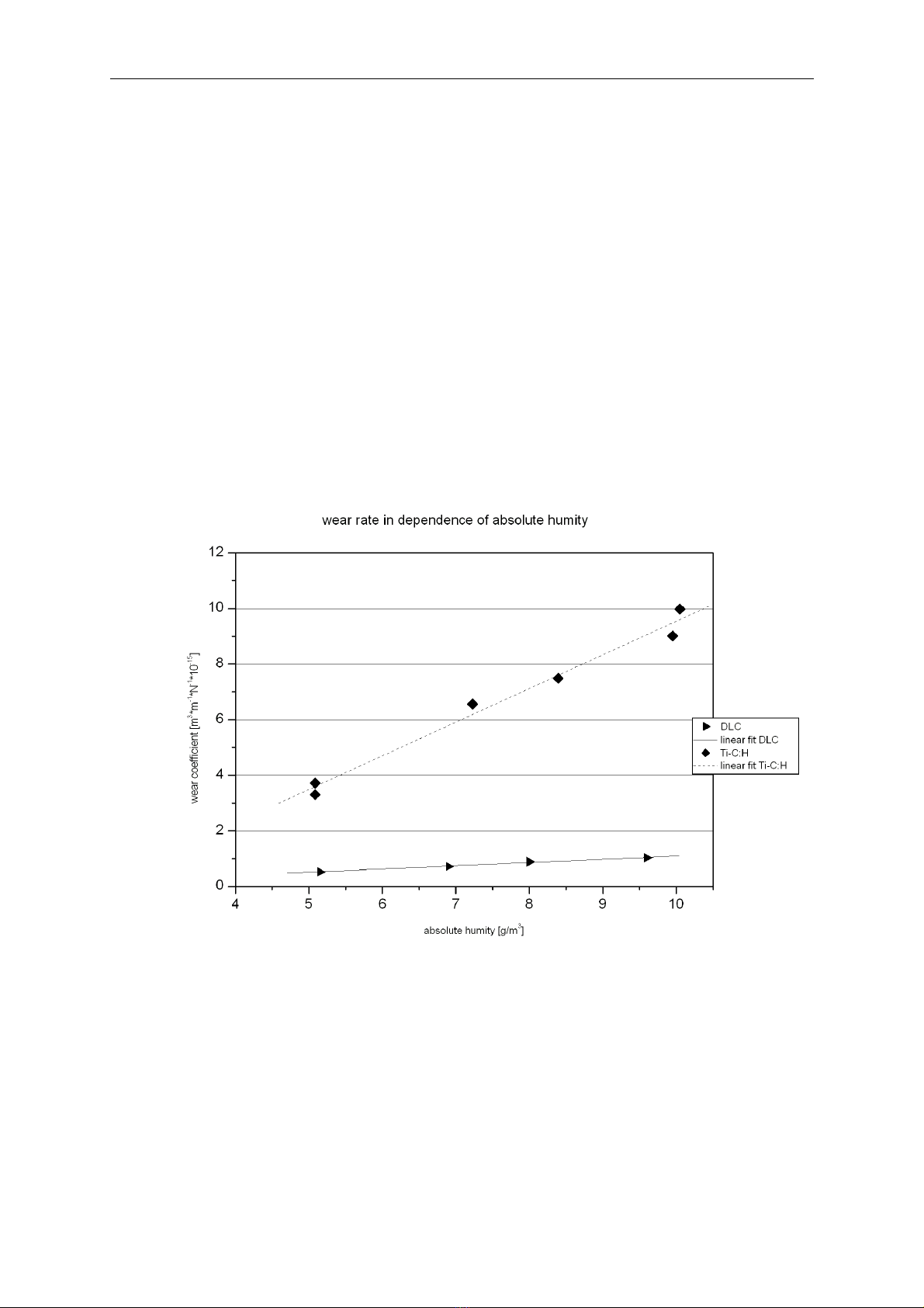
1.2 CLIMATIC INFLUENCES ON TRIBOLOGICAL PROCESSES...............................................................5
1.3 ABRASIVE SLURRY................................................................................................................5
1.4 PLACE OF INSTALLATION.......................................................................................................
1.5 HANDLING THE ABRASIVE SLURRY..........................................................................................
2 TEST PREPARATIONS.............................................................................................7
2.1 SELECTION OF THE TEST PARAMETER (GRINDING PATH / NUMBER OF REVOLUTIONS).....................7
2.2 GRINDING SPEED / BALL OR SHAFT REVOLUTIONS PER MINUTE...................................................8
2.3 BEARING STRENGTH..............................................................................................................8
2.4 CLEANING THE SHAFT...........................................................................................................9
2.5 SPECIMEN...........................................................................................................................9
2. BALL..................................................................................................................................9
2.7 AUTOMATIC DOSAGE APPARATUS...........................................................................................9
2.8 FILLING THE CARTIGE WITH ABRASIVE SLURRY........................................................................10
2.9 DOSING PARAMETERS.........................................................................................................10
2.10 MANUAL DOSAGE WITH A PIPETTE......................................................................................10
3 TEST EXECUTION...................................................................................................11
3.1 ADJUSTING THE SPECIMEN..................................................................................................11
3.2 APPLICATION OF THE ABRASIVE SLURRY (ONLY MANUAL APPLICATION)......................................11
3.3 FURTHER TESTS..................................................................................................................12
3.4 ABORTING A TEST..............................................................................................................12
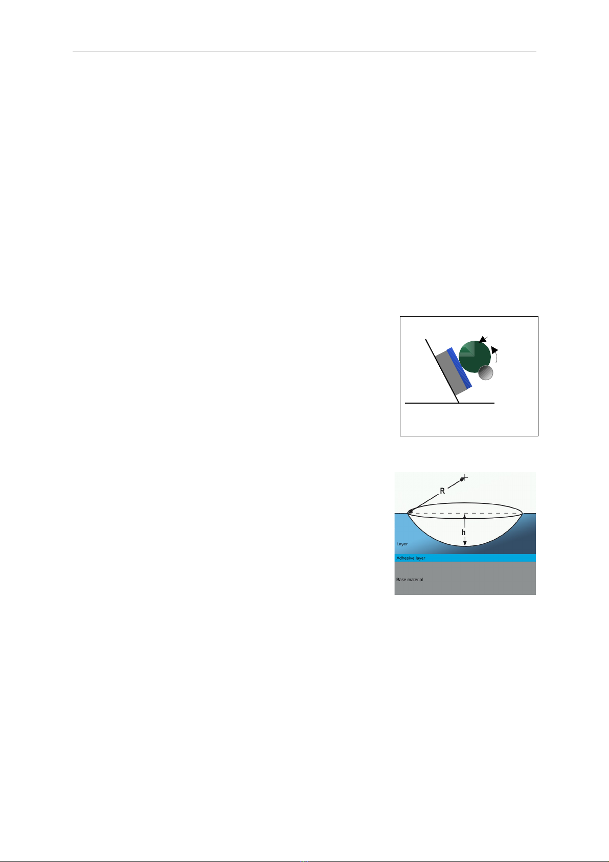
4 ANALYSIS OF THE WEAR CRATERS....................................................................12
4.1 ANALYSIS BY SURFACE PROFILER..........................................................................................13
4.2 CALCULATION OF THE WEAR COEFFICIENT..............................................................................13
4.3 ANALYSIS BY MICROSCOPE..................................................................................................14
4.4 CALCULATION OF THE WEAR COEFFICIENT .............................................................................14
5 HANDLING...............................................................................................................15
5.1 GENERAL OPERATING INSTRUCTIONS....................................................................................15
5.1.1 KEY FUNCTIONS....................................................................................................................... 15

5.1.2 THE MENUS............................................................................................................................. 1
5.1.3 TEXT INPUT............................................................................................................................. 1
5.1.4 INPUT OF NUMERICAL VALUES....................................................................................................17
5.2 GRINDING PARAMETERS......................................................................................................17
5.2.1 INPUT RANGE........................................................................................................................... 18
5.3 START / STOP...................................................................................................................18
5.4 MAIN SCREEN....................................................................................................................19
5.5 MENU...............................................................................................................................19
5. MANAGE GRINDING PARAMETERS.........................................................................................20
5. .1 CHANGE PARAMETERS............................................................................................................... 20
5. .2 SAVE PARAMETER..................................................................................................................... 20
5. .3 LOAD PARAMETER..................................................................................................................... 20
5. .4 DELETE PARAMETER ................................................................................................................. 20
5.7 CLEAN VALVE....................................................................................................................21
5.8 SYSTEM SETTINGS..............................................................................................................21
5.8.1 CONFIGURATION....................................................................................................................... 21
5.8.2 LANGUAGE.............................................................................................................................. 22
5.8.3 FACTORY SETTINGS................................................................................................................... 22
5.8.4 INFORMATION.......................................................................................................................... 22
APPENDIX 1: LICENSE INFORMATION..................................................................22

BAQ kaloMAX NT II Manual
1 General information about measuring wear resistance on thin layers
1.1 Overview
In tribological orientated development o layers and in quality assurance o wear-
protective layers, the determination o wear resistance o layers is an essential
demand.
In a collaboration between the Fraunho er Institute or Sur ace Engineering and thin
ilms (IST) and the company BAQ GmbH, the method o ball cratering tests according
to DIN EN 1071-2 has been adapted to tests o thin layers. A method or testing the
wear resistance o thin layers (µm range) has been developed.
The high-precision wear resistance tester kaloMAX NT is
use ul or abrasive wear characterization o materials and
layers. By means o an automatic dosage apparatus, an
abrasive slurry is applied onto a 100Cr6 steel ball with a
diameter o 30mm. This ball is rotating against a specimen
(see Figure).
The wear crater should be ground into the layer without
breaking through to the base material. The width and
depth o the wear crater has to be measured by means
o a sur ace pro iler or a microscope.
The wear coe icient speci ic to the abrasion slurry can
be calculated rom the volume o the wear crater, the bearing load and the grinding
path. The volume o the wear crater can be calculated rom the diameter o the
grinding ball and the depth or the diameter o the wear crater.
Bearing strength, grinding speed and grinding path must be constant to obtain
comparable wear resistance coe icients.
The minimum thickness o the layer which can be reliably measured is about 1 µm or
hard coatings. This is primarily determined by the shortness o measurement time.
Seite 4
Revolving Shaft
Sample Layer
K
u
g
e
l
Abrasive
slurry
Test Set-Up

BAQ kaloMAX NT II Manual
Furthermore the device can be used or tests according to the cap grinding method
(DIN EN 1071-2).
1.2 Climatic influences on tribological processes
As in every other tribological process, the ambient temperature and humidity a ects
the abrasion process. Naturally, this applies also to the determination o wear
resistance by means o a high-precision wear resistance tester.
Extensive measurements have been done at the FhG-IST to characterize the in luence
o di erent climatic conditions (temperature and humidity) on wear resistance o
layers.
The chart shows that the in luence o the humidity on the wear coe icient depends on
the material o the layer system.
1.3 Abrasive slurry
The abrasive slurry has been developed especially or the determination o wear
resistance o thin layers. Due to characteristic properties o this abrasive slurry, very
Page 5

BAQ kaloMAX NT II Manual
homogeneous wear craters ( ree rom deep urrows) are obtained on thin layers. This
is a basic condition or the quanti ication o the wear volume (Vv). Furthermore, the
low abrasiveness o the slurry allows measurements in the range o µm. Because o
the viscosity, the slurry does not spread out on the ball during the grinding process,
but adheres on the grinding trace around the ball. Moreover, it ensures a well-
balanced proportion between lubrication and wear process.
To obtain reproducible and comparable results, it is essential to use a slurry o
constant characteristics. There ore, it is recommended to use the abrasive slurry wich
is available as consumable supply. This slurry is made by the IST and the quality o
every 50ml-cartridge is tested. A re erence layer is provided, so you can check the
quality at any time.
1.4 Place of installation
It would be best to place the device in an air-conditioned room. I this is not possible,
the place o installation should be choosen considering the ollowing aspects:
The climatical conditions should be as constant as possible.
A separate room is advisable.
The device should not be placed close to heat sources (e.g. radiator) or windows
(solar radiation, draught).
The place o installation should not be draughty (e.g. near by a door).
1.5 Handling the abrasive slurry
To preserve the above-named (1.3) properties (viscosity) o the abrasive slurry, the
ollowing should be observed:
Open the cartridge only or short periods o time to ill the pipette with abrasive
slurry (protection against humidity absorption).
Stir up the abrasive slurry with a clean and dry stirring rod.
Page 6

BAQ kaloMAX NT II Manual
Do not keep the abrasive slurry near by heat sources (e.g. radiators, solar heat).
Most suitable would be a drawer near by the tester.
It is recommendable to use a re erence sample (e.g. standard layer) to check the
„state“ o the abrasive slurry in regular intervals. A change in viscosity o the
abrasive slurry causes mostly higher wear coe icients.
2Test preparations
The wear coe icient is calculated rom the volume o the wear crater, the bearing
strength (perpendicular to the sur ace o the specimen) and the grinding path.
2.1 Selection of the test parameter (grinding path / number of revolutions)
The appropriate grinding path (or the number o ball or sha t revolutions) and hence
the measurement duration, has to be determined experimentally according to the
requirements. The suitable value depends basically on the thickness and wear
resistance o the layer to test. It is important, that the depth o the resultant wear crater
is not greater than the thickness o the unctional layer.
The experiences o the Fraunho er Institute or Sur ace Engineering and Thin Films can
give a rough guide or the determination o the measurement duration. These values
are only valid or this special developed layer systems. For several layer systems, the
ollowing wear crater depth have been determined (20°C, 50 % relative humidity
equivalent to 7,3 [g/kg dry air] at 1013mbar).
Layer system Revolutiuons
o the ball
Measurement
duration [min]
Wear crater
depth [µm]
Wear volume
[m3*m-1*N-1*10-15]
Carbon ilms
(DLC) 540 9 0,7 0,8
Metal carbon ilms:
Ti-C:H 180 3 1,1 6,2
Metal carbon ilms:
W-C:H 180 3 0,8 3,3
Table 1: Layer systems/crater depth
The direct input o the grinding path has practical advantages over the input o the
number o ball or sha t revolutions. The calculation o number o ball revolutions
Page 7

BAQ kaloMAX NT II Manual
grinding path will be done automatically. The ball diameter must be entered. The
geometrical values o the device (distance between the supporting points, diameter o
the sha t at the supporting points) will automatically be taken into the calculation.
2.2 Grinding speed / ball or shaft revolutions per minute
The grinding speed (ball or sha t revolutions per minute) corresponds to the distance
which the sur ace o the ball covers. This also has a great in luence on the resulting
wear coe icient.
For all tests on hard coatings, 60 revolutions o the ball per minute has been used by
the IST. This is equivalent to a grinding speed o 5.6 m/min.
2.3 Bearing strength
The bearing strength cannot be measured directly. It depends on the weight and
diameter o the ball, the blade angle o the specimen and the distance between
specimen and sha t.
There ore it is recommended, to keep this values constant or a series o tests. The
sur ace o the specimen should parallel the top side o the vice so that the blade angle
is 60 °.
The distance between specimen and sha t can be adjusted by means o a gauge. Set
the gauge onto the ground plate and push it against the sha t. Then push the whole
vice with the clamped specimen against the inclined sur ace o the gauge rom behind.
The gauge must contact the sha t at both sides. The sur ace o the specimen should
contact the inclined sur ace o the gauge. Thus, the blade angle can be controlled.
Given a ball diameter o 30mm, the bearing strength is 0.54N in this position. The
adjustment has to be executed very care ully, because even small variations can lead
to di erent wear coe icients.
Page 8

BAQ kaloMAX NT II Manual
2.4 Cleaning the shaft
The contact sur aces o the rubber rings on the sha t must be cleaned with ethyl
alcohol be ore the test. I the contact sur aces o the rubber rings are contaminated
with abrasive slurry, this will decrease the riction. Furthermore, the rubber rings may
not be damaged. I the rubber rings are damaged, the whole sha t has to be replaced,
because the rings must be adjusted to the sha t.
Accurate (round) wear craters can be obtained only i the rubber rings are in a proper
state.
2.5 Specimen
The specimen has to be clamped to the vice. Clean the measuring area with ethyl
alcohol to remove pollutions (e.g. grease, oil, ingerprints etc.).
2. Ball
The ball must be cleaned with ethyl alcohol. The ball has to be ree rom abrasive
slurry. A thorough cleaning o the ball is recommended to avoid slipping at the contact
sur ace o the rubber rings. Put the ball onto the V-shaped notch on the driving sha t.
O course, the balls may not be rusted. They must be stored dry. A container with
silica gel is recommended.
2.7 Automatic dosage apparatus
The automatic dosage apparatus acilitates the application o the abrasive slurry. A
single drop will be released when the START-button is pressed. The drops have a
constant mass (pre erably 35 mg). The amount depends on the viscosity o the slurry,
dosage time and dosage pressure (see below).
Required accessories
Cartridge: 5 ccm, Polypropylene
Plug: 5ccm, Polyethylene, double seals (white)
Hollow needle: olive (1,54mm), stainless steel
Page 9

BAQ kaloMAX NT II Manual
2.8 Filling the cartige with abrasive slurry
Take care that the slurry has as ew air bubbles as possible, when illing the cartidge.
Close the cartidge with a blind plug and then ill it maximum hal - ull.
Push the plunger down the cartridge until it touches the abrasive slurry. The air in the
cartridge can escape at the side o the plunger . Take care, that there is no air between
the plunger and the abrasive slurry! Be care ul, that the abrasive slurry is not pressed
between the plunger and the cartridge wall. Now the cartridge adapter and the needle
are astened.
2.9 Dosing parameters
Be ore the dosing process can start, pressure and duration must be set.
Parameters or a drop with a mass o about 35 mg :
Pressure: 0.45 bar
Duration: 150 ms
The pressure is adjusted by a ine setting valve at the rear side o the device. The
duration can be programmed in the menu.
When the cartridge has just been illed, the slurry must irst be pressed into the
needle. There ore, no drop will be build the irst ew times the START-button is
pressed. It is not recommended to use the irst 5-6 drops or measurements.
The drop size is constant with a tolerance o about 1 mg.
A single drop can be released by pressing the STOP-button when the main screen is
displayed unless a grinding is in progress.
2.10 Manual dosage with a pipette
A rubber bulb is attached to a clean pipette. Only clean pipettes should be illed with
abrasive slurry (draw up). The abrasive slurry should be stirred up with the provided
Page 10

BAQ kaloMAX NT II Manual
stirring rod. The slurry should not be drawn up rom the bottom o the bottle but rom
the middle o the illing quantity. Clean the outside o the pipette. Then place the
pipette into the holder.
Abrasion slurry once taken rom the bottle should not be put back.
3 Test execution
Be sure that you have followed all test preparation instructions.
3.1 Adjusting the specimen
The vice with the clamped specimen can be moved in x-y-direction. The optional laser
pointer acilitates the positioning o the specimen.
I a ball with a diameter o 30 mm is used and the sur ace o the probe has been
adjusted by means o the gauge, the laser pointer points to the spot on the sur ace o
the specimen where the ball will grind the spherical cap.
The laser pointer will be switched on automatically, when it has reached its inal
position.
3.2 Application of the abrasive slurry (only manual application)
I the automatic dosage apparatus is not used, the abrasive slurry must be applied
manually be ore doing a test.
Each test requires only 1 drop (see igure) o abrasive
slurry. This applies to all indicated test durations.
Exert slight pressure on the rubber bulb until a drop o
slurry is ormed. The drop should come o the pipette
by sel -weight. This should ensure that the drops have
a constant mass. Take heed that there are no air
bubbles in the drop, otherwise the ball must be
cleaned and a new drop must be applied.
Page 11
Picture 1: Drop o abrasive
slurry applied to the ball

BAQ kaloMAX NT II Manual
A ter a running-in period o about 0.5 min, the abrasive slurry should be evenly spread
around the ball (see igure).
3.3 Further tests
Remove the ball rom the sha t and clean it with ethyl alcohol. Also clean the
specimen. The probe can be moved and urther tests can be made. The grinding
craters should have a minimal distance o 1-2mm.
3.4 Aborting a test
A test should be aborted when the ball begins to tumble. Probably a bit o the abrasive
slurry has spread on to the rubber rings or the ball or the specimen has not been
cleaned su iciently.
4 Analysis of the wear craters
The wear craters can be measured by means o a sur ace pro iler (depth o the crater)
or a microscope (diameter o the crater).
Page 12
Picture 2: Evenly spread
abrasive slurry

BAQ kaloMAX NT II Manual
4.1 Analysis by surface profiler
For an analysis by a sur ace pro iler (determination
o the depth o the wear crater), the scan should be
taken at right angle to the grinding direction and
along the centre line (deepest point o the wear
crater). See igure.
4.2 Calculation of the wear coefficient
For the calculation o the wear volume, an ideal spherical cap is assumed. The crater
i.e. wear volume (Vv) can be calculated as ollows:
h) -r (3 h
3
= v
2
V
where: Vv= Wear volume [m3]
h = Crater depth [m]
r = Ball radius [m]
Then the wear coe icient (Vr) can be determined:
Vr=Wear volume
Slidingdistance∗Bearing strength
The grinding path (s) can be calculated rom the periphery o the ball and the number
o ball revolutions n.
n r 2 = s
Page 13
( 1 )
( 2 )
( 3 )
Drawing 1: Analysis o a wear
crater by a sur ace pro iler
Wear
crater
Grinding
direction
Stylus

BAQ kaloMAX NT II Manual
The ormula or the wear coe icient is:
K
v
r
F s
V
= V
Vr= Wear coe icient [m3*m-1*N-1]
Vv= Wear volume [m3]
s = grinding path [m]
FK= Bearing strength [N]
A bearing strength (Fk) o 0.54 N can be adjusted by means o the provided gauge.
The unit o the wear coe icient should be given as m3*m-1*N-1. It is not recommended
to reduce the units, because the source units should be kept recognizable.
4.3 Analysis by microscope
For an analysis by microscope, the diameter o the wear crater has to be measured.
4.4 Calculation of the wear coefficient
The depth o the wear crater is calculated rom the diameter. An ideal spherical cap is
assumed.
The ormula or the depth o the wear crater is:
h = r - r - r
2
2
h = Depth o the wear crater [m]
r = Ball radius [m]
r1= Crater radius [m]
The wear coe icient can be calculated with ormula ( 1 ) and ormula ( 4 ) (see chapter
4.2 Calculation o the wear coe icient).
Page 14
( 4 )

BAQ kaloMAX NT II Manual
5 Handling
5.1 General operating instructions
5.1.1 Key functions
By pressing this key the user exits the current unction and enters the
superordinate menu item. Changed settings are not imported.
Using this key completes the editing in one ield or selects a subordinate
menu item.
Function key
Function key
Function key
Function key
Pressing this key starts the grinding process (see chapter 5.3 Start / Stop ).
Pressing this key during grinding stops the grinding process (see chapter 5.3
Start / Stop). Otherwise, the valve is cleaned (see chapter 5.7 Clean valve).
Cursor keys
These keys are used to select menu items and to move the cursor within the
input ields.
In certain situations, unction keys F1 to F4 are used to simpli y handling, e.g. to
quickly change the major grinding parameters in the main screen without having to
enter the menu.
The number keys are used to enter numerical values.
Page 15

BAQ kaloMAX NT II Manual
5.1.2 The menus
A menu consists o a list o available menu items
the highlighted one o which is the active menu
item. With the ▲ and ▼ cursor keys you select
the active menu item.
ENTER
selects the active
menu item and either opens a screen or sub
menu.
ESC
brings the user back to the previous menu.
5.1.3 Text input
Saving the grinding parameters requires input in plain text. In this case, a text input
ield opens.
In the upper ield highlighted in white (called text ield herea ter), the entered text is
shown. The previous lines show the characters that can be selected. A space is
represented by [ ].
The cursor keys move the cursor through the character ields and select a character by
pressing
ENTER
. The selected character appears in the text ield.
F1 switches between upper and lower case, F2 deletes the last character in the text
ield.
F4 (OK) exits text input and the entered text is now available.
ESC
and F3 (Cancel) exits text input without saving.
Page 16
Picture 2 : Text input
Picture 1: Menu

BAQ kaloMAX NT II Manual
5.1.4 Input of numerical values
Open the number input screen to enter numerical values. In the ield highlighted in
white the entered number is displayed. The ◄ and ► cursor keys are used to shi t the
cursor in the ield. F2 (←) deletes the character le t o the cursor. Numerical values and
the decimal separator are entered by using the appropriate keys.
F4 (OK) or ENTER key completes the input and saves the value.
F3 (Cancel) or ESC aborts the input.
5.2 Grinding parameters
The ollowing parameters have to be de ined or the grinding process:
•Grinding speed (m/min), ball RPM or sha t RPM
•Grinding path (m), number o ball revolutions or number o sha t revolutions
•Dosage time o the abrasive slurry (ms)
•Diameter o the grinding ball
Furthermore, the ollowing basic settings can be made:
•Unit in which speed has to be entered (grinding speed, ball revolutions per minute
or sha t revolutions per minute)
•Unit in which the grinding path has to be entered (meter, number o ball
revolutions or number o sha t revolutions)
These parameters (with basic settings) can be saved and retrieved at a later point o
time. The current parameters can be changed in the main screen (see chapter5.4) or
via the menu (see chapter 5.6.1); stored parameters have to be loaded irst, be ore
they can be altered and stored again.
The con iguration serves to de ine the basic settings (see chapter 5.8.1).
Page 17

BAQ kaloMAX NT II Manual
The pre-pressure or pneumatic dosage can be adjusted by using the rotary knob on
the back o the device. The setting is shown on the upper le t part o the main screen.
5.2.1 Input range
Minimum Maximum
Speed
Ball revolutions 15 /1/min 590 /1/min
Grinding speed 1.4 /m/min 55.8 /m/min
Sha t revolutions 30 /1/min 1000 /1/min
Distance
Number o ball revolutions 13 /UB9200 /UB
Grinding path 1.2 /m 870 /m
Number o sha t revolutions 20 /US15000 /US
Grinding ball diameter 12 /mm 40 /mm
5.3 Start / Stop
Press START on the main screen to start the grinding process.
A small amount o grinding suspension is put on the grinding ball, i.e. the valve opens
or the de ined dosage time.
A ter a pause o 1.5 seconds, the motor starts.
The grinding process can be aborted anytime by pressing the STOP button. The
grinding process ends a ter the grinding path has been covered or the number o
revolutions has been completed.
Page 18

BAQ kaloMAX NT II Manual
5.4 Main screen
Press the START button on the main screen to start the grinding process.
The current parameters are displayed and can be changed a ter pressing the
corresponding unction key. I a set o parameters is loaded, the data record name is
indicated in lower le t corner o the screen. Changing the parameters in the main
screen has no e ect on the stored parameters.
I no grinding operation is in progress, the valve can be cleaned by pressing the STOP
key.
5.5 Menu
Press ESC when the main screen is visible to enter the menu. In the menu, you can
choose the ollowing items:
Grinding – the main screen is shown.
Grinding parameters – display o the sub-menu or grinding parameter setting and
managing.
Clean valve – opens the valve or the dosage time.
System – display of sub-menus for system settings
Page 19

BAQ kaloMAX NT II Manual
5. Manage grinding parameters
5. .1 Change parameters
Grinding speed, grinding path, dosage time and ball diameter can be changed
–in the main screen by pressing the corresponding unction key or
–by selecting the appropriate menu item in the sub-menu Grinding parameter /
Edit.
The unit in which the grinding speed and the grinding path have to be entered are
determined in the system con iguration (see chapter 5.8.1).
In any case, an input screen appears, where the value o the parameter can be
changed.
5. .2 Save parameter
Under the menu item Grinding parameter / Save, the current grinding parameters can
be saved with a chosen name.
A ter selection o the menu item, a text input screen comes up where the user can
enter the new data record name.
5. .3 Load parameter
Under menu item Grinding parameter / Load, it is possible to retrieve the stored
grinding parameters.
Use the ▲ and ▼ cursor keys to select the required data record rom the list o
available grinding parameters and load it by pressing ENTER.
5. .4 Delete parameter
I a stored grinding parameter record is not required any more, it can be deleted under
menu item Grinding parameter / Delete.
Page 20
Table of contents
Other BAQ Test Equipment manuals
Popular Test Equipment manuals by other brands

Elenco Electronics
Elenco Electronics RS-400/K-37 Assembly and instruction manual

Hydac
Hydac CTM-EF 3 Series Installation and maintenance instructions

AOIP
AOIP CP6632 user manual

Macmesin
Macmesin MultiTest-xt Assembly and installation

Tektronix
Tektronix SD-24 user manual

Multimetrix
Multimetrix XG 2102 user manual