BAQ alphaDUR mini User manual

alphaDUR mini
Manual
Version 1.2


Contents
1 Introduction................................................................................................5
2 Manual.......................................................................................................6
2.1 Lettering..............................................................................................6
2.2 Text boxes...........................................................................................6
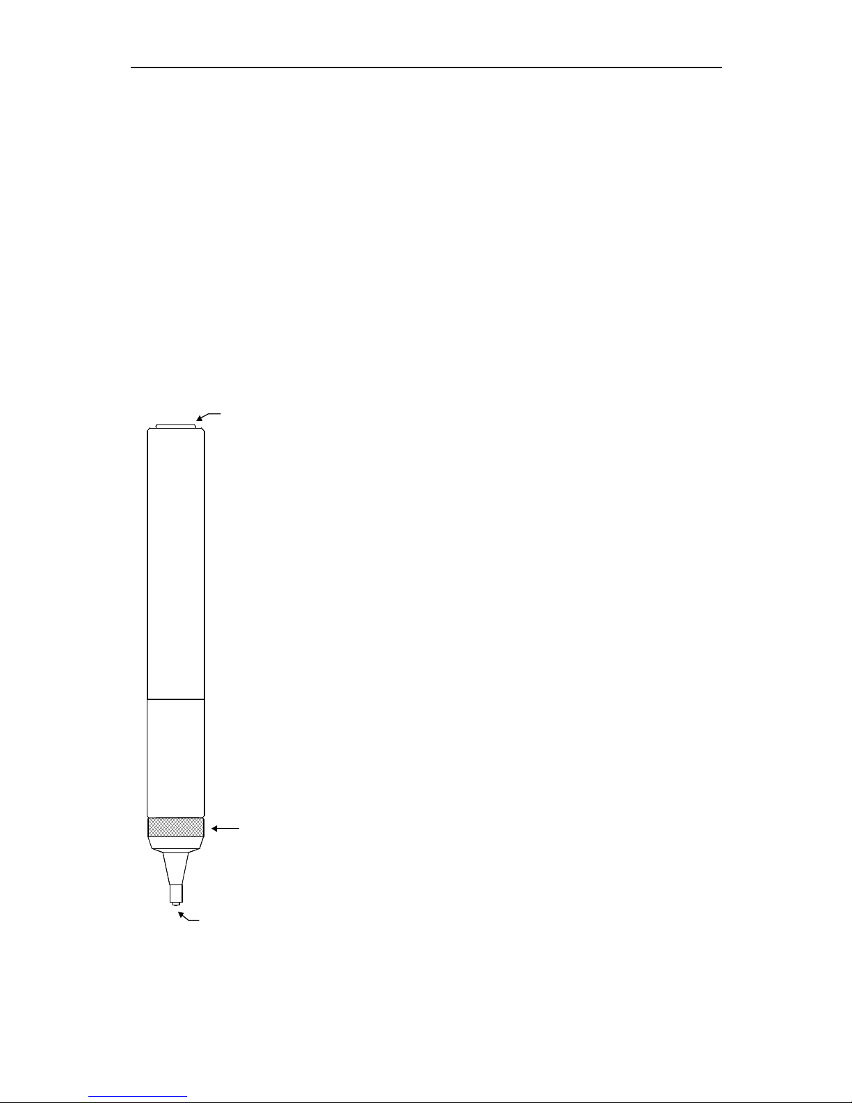
3 The test probes..........................................................................................7
3.1 Probe selection...................................................................................7
3.2 Probe handling....................................................................................7
4 eneral working instructions.....................................................................9
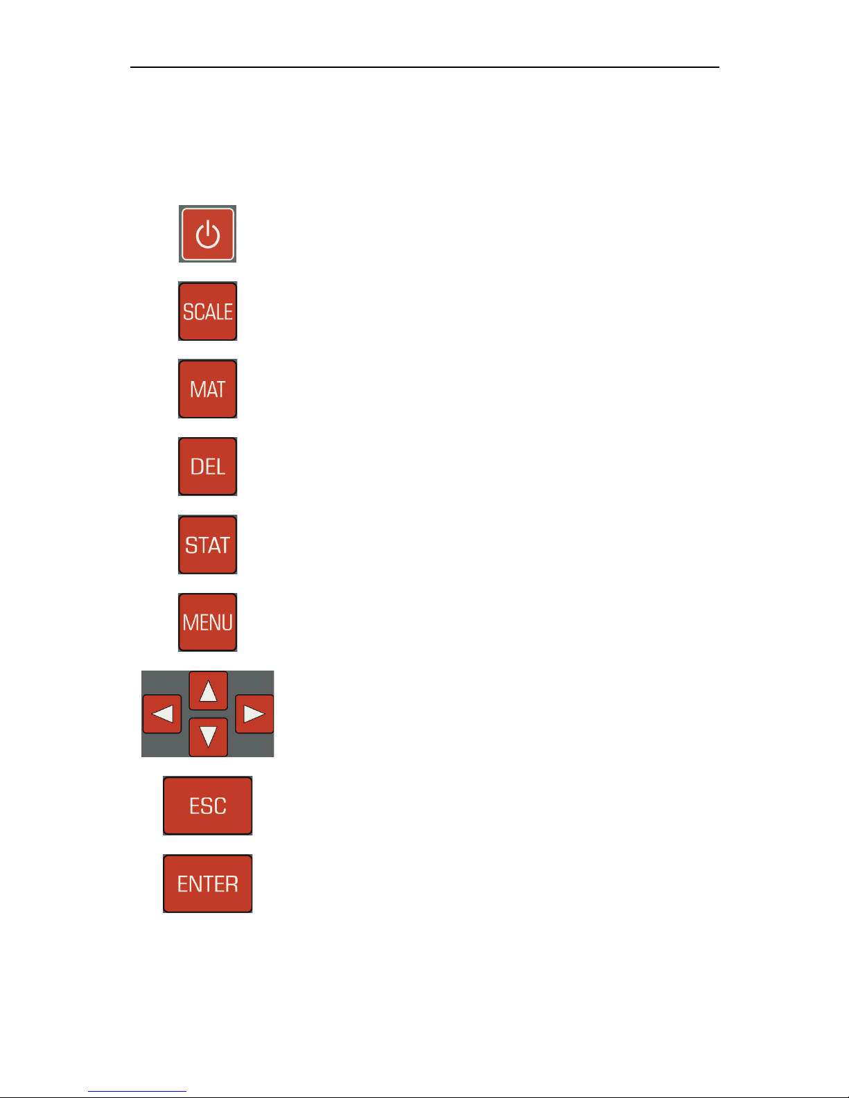
4.1 Key functions.......................................................................................9
4.2 Status bar............................................................................................10
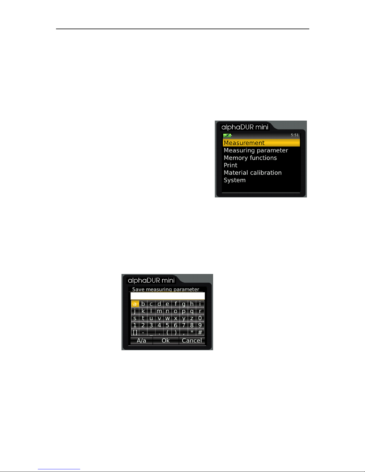
4.3 The menus..........................................................................................10
4.4 Text entry.............................................................................................10
4.5 The number field.................................................................................12
5 Measurement.............................................................................................13
5.1 Specimen requirements......................................................................13
5.2 Measuring parameter..........................................................................14
5.3 Measuring procedure..........................................................................15
5.4 Measuring window..............................................................................15
5.4.1 Key assignment of the measuring window...................................16
5.5 Statistics..............................................................................................17
5.5.1 Display of statistics.......................................................................17
5.6 Instant printout....................................................................................19
6 Measuring parameter................................................................................20
6.1 Description..........................................................................................20
6.2 Managing sets of measuring parameter..............................................21
6.2.1 Editing measuring parameter........................................................21
6.2.2 Saving measuring parameter........................................................21
6.2.3 Loading measuring parameter......................................................22
6.2.4 Deleting a set of measuring parameter.........................................22
7 Hardness conversion.................................................................................23
8 Material calibration....................................................................................23
9 Memory functions......................................................................................26
9.1 Creating a new series.........................................................................27

9.2 Continuation of a series......................................................................27
9.3 Deleting a series.................................................................................27
9.4 Displaying a series..............................................................................27
9.5 Optional: Copying of series to an USB flash drive..............................27
10 System settings.......................................................................................28
10.1 Language..........................................................................................28
10.2 Time..................................................................................................28
10.3 Date...................................................................................................28
10.4 Configuration.....................................................................................28
10.4.1 Date format.................................................................................28
10.4.2 Key SCALE.................................................................................28
10.4.3 Key MAT.....................................................................................29
10.4.4 Query whether series should be saved......................................29
10.4.5 Query whether values should be printed....................................29
10.4.6 Tensile strength unit....................................................................30
10.5 Factory defaults.................................................................................30
10.6 System information...........................................................................30
10.7 Unlock options...................................................................................30
11 Maintenance and inspection....................................................................30
12 The UCI method......................................................................................31
13 Proper disposal........................................................................................33
13.1 Deutsch.............................................................................................33
13.2 Français............................................................................................33
13.3 Italiano...............................................................................................33
13.4 Español.............................................................................................34
14 Technical Data.........................................................................................35
15 Option: Copying of series to an USB flash drive.....................................37
15.1 Transfer Data....................................................................................37
15.2 Unlock options...................................................................................37
Appendix 1: License information...................................................................38

INTRODUCTION
1 Introduction
The alphaDUR mini is a portable hardness tester. Vickers hardness is
measured according to the UCI (Ultrasonic Contact Impedance) method.
The measured Vickers hardness can be converted to Brinell hardness (HB),
Rockwell hardness (HRC or HRB) or tensile strength (N/mm2) according to DIN
standard 50150.
Up to 100 000 readings including hardness, date, time and measuring
parameter can be stored to the internal memory of the alphaDUR mini.
The memory can be divided into sections for use by different users or projects.
Saved series of measurements, including statistics, can be readily displayed or
printed. The program alphaSOFT (not included with the alphaDUR mini) is
used to transfer the series to a PC.
In addition to the permanent storage, the readings can be temporarily saved so
that statistics can be computed even if the readings are not permanently saved.
Furthermore, the alphaDUR mini provides a so called 'instant printout' function.
The readings will be instantly printed after measurement. No statistics will be
calculated.
5

MANUAL
2 Manual
2.1 Lettering
Operating elements Operating elements
KEY Keys
Standard text Descriptions and explanations in text form
Important notes Important notes and remarks
2.2 Text boxes
Operating elements Explanations of functions and operating
elements are framed in blue.
Entry fields reen fields describe user inputs and
parameters
Information Information and notes are provided with yellow
background
Important notes Important notes and warnings are represented
in red boxes
6

THE TEST PROBES
3 T e test probes
3.1 Probe selection
alphaDUR UCI test probes are available with test loads of 10, 20, 30,
49, and 98 N. This corresponds to HV1, HV2, HV3, HV5 and HV10 (1, 2,
3, 5 and 10 kg).
So the optimal load for a particular test task can be chosen. Two criteria
are crucial for the selection of the appropriate test load: surface of the
specimen and handling. For rough surfaces, high test loads are recom-
mended, which leads to greater indentations. But it ought be considered,
that it may be necessary to apply a
load of up to 10 kg manually. This is
not a problem if the probe is fixed in a
stand. But it could be difficult to apply
the test load steadily and vertically if
many consecutive measurements
must be done.
3.2 Probe andling
The protective sleeve serves 2 pur-
poses:
It protects the UCI rod against dam-
ages (as distortion).
It serves as a mechanical stop for the
deflection of the rod during measure-
ment.
To conduct a measurement, the probe
must be held perpendicular to the
specimen surface. (The alphaDUR
mini has to be calibrated to the mater-
7
Cable
connector
Protective
sleeve
Oscillating rod with
Vickers diamond
Fig. 1

THE TEST PROBES
ial and must be in measuring mode.) The Vickers diamond may touch the
surface slightly, but not for too long (otherwise an error occurs). Then the
probe is pressed to the specimen until the protective sleeve hits the sur-
face. An acoustic signal indicates the completion of the measurement. To
achieve an accurate measurement, the probe must be pressed steadily
and vertically onto the specimen.
To facilitate the measurement procedure, probe supports can be at-
tached to the probe in place of the protective sleeve. These probe sup-
ports are obtainable for flat and convex surfaces.
A high precision stand is available, which eases load application, particu-
larly when a large number of measurements has to be taken or in case of
a high test load.
8

ENERAL WORKIN INSTRUCTIONS
4 General working instructions
4.1 Key functions
Switching on/off the device.
Changes the hardness scale.
Changes the material.
Delete last measurement point
Display statistics
Into the main menu
Cursor keys
With these keys, menu items are selected and the re-
quired values in input fields fields are set.
With this key, the current function is exited. The higher-
level menu item is accessed.
The processing is completed with this key in a field, or a
menu item is selected.
9

ENERAL WORKIN INSTRUCTIONS
4.2 Status bar
The rechargeable battery status and the time are displayed in the status bar at
the top of the window.
4.3 T e menus
A menu consists of a list of available menu items and a bar which identifies the
active menu item. This bar can be displaced in
the menu with the aid of the cursor keys ▲ and
▼. As a result of pressing ENTER the marked
menu item is selected. Either a window or a
submenu are opened by that.
With ESC, a return is made to the former menu.
Particular attention has been paid to ease the
operation by avoiding deeply nested menus.
4.4 Text entry
In case of saving measuring data and measuring parameters, inputs are
possible in plain text. In these cases, the text entry window is opened.
In the upper field (designated as text field in the following) the entered text is
displayed, in the rows below are represented the characters which can be
selected. The blank is identified with [ ].
Below the characters is located a strip with command buttons for control. These
command buttons are allocated as follows:
10
Fig. 3 : Text entry
Fig. 2: Main menu

ENERAL WORKIN INSTRUCTIONS
The field on which the focus is placed is identified by a yellow background. With
the keys ▲ and▼ the focus is set on the line above or below the current line.
The allocation of the keys is different, depending on which field has the focus at
the time.
11
A/a Switching between upper case and lower case
OK Accepting text and closing text entry window
Cancel Closing text entry window without accepting the text
Action Key/s
Focus on text field
Shift input mark ◄ and►
Deletion of the character in front of the input mark DEL
Accepting text and closing text entry window ENTER
Closing text entry windows and asking whether the text
should be accepted.
ESC
Focus on character area
Selection of the character to the left or right of the current
character
◄ and►
Entering character in the text field ENTER
Deletion of the last entered character DEL
Closing text entry windows and asking whether the text
should be accepted.
ESC
Focus on command button
Implement action ENTER
Selection of the command button to the left or right of the
current one
◄ and►
Deletion of the last entered character DEL
Closing text entry windows and asking whether the text
should be accepted.
ESC

ENERAL WORKIN INSTRUCTIONS
4.5 T e number field
A number field is used for the input of numbers. It consists of mostly several
digits which can be changed separately, and a marker (cursor) which can be
displaced with the cursor keys ◄ and ► within the number field. The Item on
which the cursor is at this time can be modified through pressing the cursor
keys ▲ and ▼
A further, leading digit for the input of larger numerical values can be generated
by cursor ◄.
The input is saved and concluded with ENTER. With ESC, the entry field is
closed without saving.
12
Action Key/s
Displace marker ◄ und ►
Increase digit ▲
Decrease digit ▼
enerating a further, leading digit if the marker is placed on
the first digit.
◄
Accepting input and closing number field ENTER
Closing number field and discard input. ESC

MEASUREMENT
5 Measurement
The measurement can be started with the menu item Measurement. If a probe
is connected to the alphaDUR mini, the measurement window will by shown
directly after start-up.
The test load of the connected probe will be detected automatically.
5.1 Specimen requirements
As in all hardness tests, besides the hardness of the specimen some other
characteristics can influence the measurement result. These characteristics
include the surface quality, the thickness and the homogeneity of the specimen.
Some essential requirements have to be fulfilled to achieve reliable
reproducible hardness values.
Surface quality
The surface quality should be the same as for optical Vickers hardness
tests according to DIN standard. For low test loads, the quality has to be
higher than for high test loads. The surface must be free from oxides, im-
purities and lubricants. The surface roughness should not exceed 1/5 of
the penetration depth.
Thickness
For optical Vickers hardness tests, the thickness of the specimen should
be at least ten times higher than the penetration depth. This applies also
to the thickness of coatings.
The UCI method requires a higher thickness, because the oscillations of
the UCI rod are transmitted to the specimen. They spread over the speci-
men and will be reflected at the boundaries. These reflected oscillations
influence the frequency shift in the UCI rod and affect the accuracy of the
measurement.
13

MEASUREMENT
To avoid this effect, the specimen has to be thick enough to allow the os-
cillations to attenuate before the diamond is reached. With thin speci-
men, the mass of the specimen has an effect. If the mass of the speci-
men is high enough, a thickness of 8 mm for flat specimen or 10 mm for
round stock is sufficient. If a specimen does not meet these require-
ments, it can be acoustically coupled to a massive support e.g. with a
thin oil film between specimen and support. A steel plate is recommen-
ded as support (e.g. the precision stand comes with an appropriate
plate).
Small, irregular shaped parts can be embedded in plastic material.
Homogeneity
As in optical Vickers hardness tests, the indentations are relative small.
Therefore the homogeneity of the specimen can possibly influence the
measurement results. To achieve reproducible hardness readings, the in-
dentation must be significantly greater than the grain size of the test ma-
terial. This may be not the case for some cast material even with a test
load of 100N.
5.2 Measuring parameter
The measuring parameter must be set according to the demands. The
parameter are in particular:
Material
Hardness scale
Rating
Statistics
Instant printout
These parameter are described in detail in chapter 6.2. Select the menu item
Measuring parameter/Edit to adjust them. If a set of measuring parameter that
14

MEASUREMENT
meets the requirement already has been saved, you can use the menu item
Measuring parameter/Load (see 6.2.3) to reload them.
After power-up, the alphaDUR mini restores the measuring parameter which
were last used.
5.3 Measuring procedure
To take a measurement, put the probe vertically onto the specimen and press it
down steadily as far as it will go. The hardness value will be determined shortly
before the protective sleeve touches the surface of the specimen. Therefore
vibrations caused by the protective sleeve hitting the surface will not influence
the measurement result. The measurement is completed when you hear the
beep. The number of fractional digits shown depends on the hardness scale.
Rockwell scales will usually be displayed with 1 fractional digit, Vickers, Brinell
and tensile strength without any fractional digits.
Within certain boundaries, the speed with which the probe is pressed down has
no influence on the measurement result. If the probe is lowered too fast or if the
probe is not raised from the specimen for some time, an error message will be
shown.
5.4 Measuring window
15
Fig. 4: Measuring window

MEASUREMENT
5.4.1 Key assignment of t e measuring window
16
C arge status display:: Displays the residual charge of the batteries.
Time: Current time
Measured value: Current measured value
Hardness scale: Current hardness scale
Material: Current material
Number of
measurements:
Number of measurements already carried out
Average value: Average value of the measurements carried out
Standard deviation: Standard deviation
History: The last 4 measured values are displayed here
SCALE Changes the hardness scale.
If the tolerance limits cannot be converted to the new scale,
they are automatically set to 0. However, the values set-
adjusted in the measuring parameters are stored so that, in
case of renewed changeover into a scale in which the limits
can be converted, these are again set to the adjusted values.
In the system settings it can be determined whether the scale
should be changed automatically or a dialogue should be
opened (see 10.4.2).
Deactivated if t e measured value memory is switc ed on.
MAT Changes the material. If the currently selected hardness scale
is not defined for the new material, the hardness scale is
automatically reset to HL.
In the system settings it can be determined whether the
material should be changed automatically or a dialog should be
opened (see 10.4.3).
Deactivated if t e measured value memory is switc ed on.
DEL Deletion of the last measured value
STAT Display of the statistics concerning the already measured
values

MEASUREMENT
5.5 Statistics
If the measured value memory is switched on, the values of a series can be
evaluated statistically at all times. Even if the measured value memory is not
switched on, the hardness numbers are always temporarily stored until the
measurement window is closed. Thus a statistical evaluation of the measured
values can also be displayed with switched off measured value memory.
If the hardness scale or material is changed by key press in the measurement
window, the statistics are reset.
5.5.1 Display of statistics
The output of the statistical evaluation is implemented as soon as the number
of measurements set-adjusted in the measuring
parameters have been made, or the key STAT is
pressed. First to be displayed are average value,
standard deviation, relative standard deviation
(standard deviation in % of the average value),
minimum, maximum and the number of values.
Standard deviation and average value are
displayed with 1 decimal place more than is
usual for the hardness scale. The Rockwell scales are usually indicated with 1
decimal place, Vickers, Brinell, Shore and tensile strength without any decimal
place. The relative standard deviation is displayed with 2 decimal places.
If the key STAT is pressed again in this view, a window is opened in which are
displayed the measured values with which the statistics were calculated. Here it
is possible to change or to delete obviously incorrect values.
17
Fig. 5: Statistics

MEASUREMENT
To change a value the marker is set to the corresponding value with the cursor
key and then ENTER is pressed. Now a number entry field (see 4.5) is opened
and the measured value can be edited. With ENTER the change is accepted,
with ESC the number input is closed without accepting the change.
For the deletion of a value, the marker is set with the cursor key to the value to
be deleted and then DEL is pressed.
If the edit window is closed with ESC, a request is made as to whether the
changes should be accepted or rejected. If the changes are accepted, the
statistical values will be newly calculated.
The statistics window is closed with ESC. If the predetermined number of
statistical data is not yet reached (because the display of statistics was started
with key STAT or because a value has been deleted) the measurement series
will be continued.
The alphaDUR mini can be configured to display a query whether the data
should be saved as a new series (see 10.4.4) if the predetermined number of
data is reached when the window is closed. Likewise, it is possible to have a
query displayed whether the data should be printed (see 10.4.5).
18
Fig. 6: Values

MEASUREMENT
5.6 Instant printout
If a mobile printer is connected, a consecutive printout can be made. The
measured data are then instantly printed. The instant
printout mode stays active when the measuring window is
closed. It must be explicitly deactivated (see chapter
6.2.1).
19
Fig.

MEASURIN PARAMETER
6 Measuring parameter
6.1 Description
After power-up, the alphaDUR mini restores the last used measuring
parameter.
T e measuring parameters in detail:
Mat e r i al : The currently selected material calibration. For details
about material calibration see chapter 8.
Hard n e s s sc a l e : The current hardness scale (Vickers (HV), Rockwell (HRC
or HRB), Brinell (HB) or tensile strength (N/mm2)), to
which the readings will be converted. The result of an UCI
measurement is Vickers hardness. If another hardness
scale is selected, the values will be converted according
to DIN standard 50150. In the measurement window the
hardness scale can be switched with the aid of the key
SCALE, unless the measured value memory is activated.
Rat i n g : These are the upper and lower limits for rating. A signal of
2 short beeps sounds if a measured value lies outside
these limits. A single beep sounds if the value is rated
OOD.
If both limits are set to 0, no rating will be done.
It is self-evident, that the the upper limit must be higher
than the lower limit.
If rating is activated, in will be indicated in the measuring
window when the upper or lower limit is exceeded.
Sta t i s tics : The number of measured values which should be
statistically evaluated without the use of the measured
value memory is defined here.
Ins t a n t p r in tout : If a mobile printer is connected, a consecutive printout can
be made (see 5.6). This parameter can be set On or Off.
20
Other manuals for alphaDUR mini
1
Table of contents
Other BAQ Test Equipment manuals