Barco R9849975 User manual

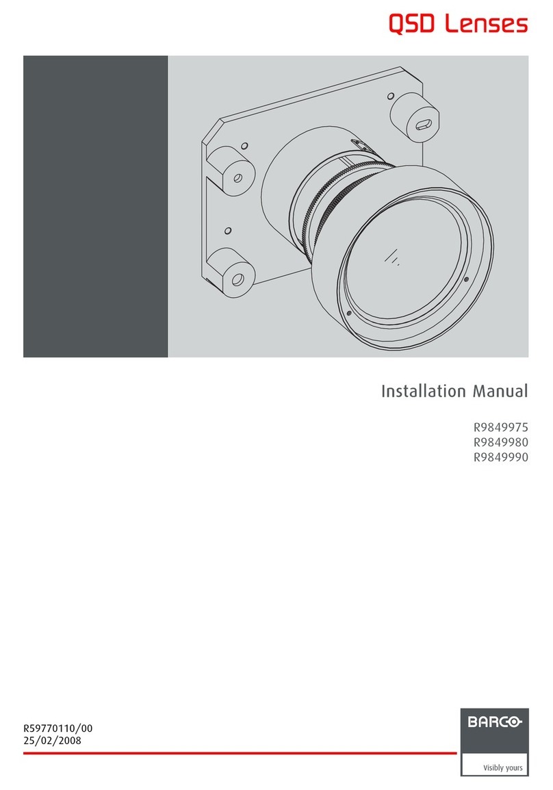
QSD Lenses
Installation Manual
R9849975
R9849980
R9849990
R59770110/01
03/11/2008

Barco nv Simulation Division
Noordlaan 5, B-8520 Kuurne
Phone: +32 56.36.82.11
Fax: +32 56.36.84.86
E-mail: [email protected]
Visit us at the web: www.barco.com
Printed in Belgium

Changes
Barco provides this manual ’as is’ without warranty of any kind, either expressed or implied, including but not limited to the implied war-
ranties or merchantability and fitness for a particular purpose. Barco may make improvements and/or changes to the product(s) and/or the
program(s) described in this publication at any time without notice.
This publication could contain technical inaccuracies or typographical errors. Changes are periodically made to the information in this
publication; these changes are incorporated in new editions of this publication.
Copyright ©
All rights reserved. No part of this document may be copied, reproduced or translated. It shall not otherwise be recorded, transmitted or
stored in a retrieval system without the prior written consent of Barco.
Guarantee and Compensation
Barco provides a guarantee relating to perfect manufacturing as part of the legally stipulated terms of guarantee. On receipt, the purchaser
must immediately inspect all delivered goods for damage incurred during transport, as well as for material and manufacturing faults Barco
must be informed immediately in writing of any complaints.
The period of guarantee begins on the date of transfer of risks, in the case of special systems and software on the date of commissioning,
at latest 30 days after the transfer of risks. In the event of justified notice of complaint, Barco can repair the fault or provide a replacement
at its own discretion within an appropriate period. If this measure proves to be impossible or unsuccessful, the purchaser can demand a
reduction in the purchase price or cancellation of the contract. All other claims, in particular those relating to compensation for direct or
indirect damage, and also damage attributed to the operation of software as well as to other services provided by Barco, being a component
of the system or independent service, will be deemed invalid provided the damage is not proven to be attributed to the absence of properties
guaranteed in writing or due to the intent or gross negligence or part of Barco.
If the purchaser or a third party carries out modifications or repairs on goods delivered by Barco, or if the goods are handled incorrectly,
in particular if the systems are commissioned operated incorrectly or if, after the transfer of risks, the goods are subject to influences not
agreed upon in the contract, all guarantee claims of the purchaser will be rendered invalid. Not included in the guarantee coverage are
system failures which are attributed to programs or special electronic circuitry provided by the purchaser, e.g. interfaces. Normal wear as
well as normal maintenance are not subject to the guarantee provided by Barco either.
The environmental conditions as well as the servicing and maintenance regulations specified in the this manual must be complied with by
the customer.
Trademarks
Brand and product names mentioned in this manual may be trademarks, registered trademarks or copyrights of their respective holders.
All brand and product names mentioned in this manual serve as comments or examples and are not to be understood as advertising for
the products or their manufacturers.

Table of contents
TABLE OF CONTENTS
1. Kit description ...................................................................................................... 3
1.1 Kit content ............................................................................................................................ 3
1.2 Lens range . . . ......................................................................................................................... 3
1.3 Domain of application ................................................................................................................ 3
1.4 Lens formulas......................................................................................................................... 3
2. Installing the lens .............................. .................... .................... .................. .......... 5
2.1 Installing the lens and adjusting the Scheimpflug ................................................................................... 5
2.2 Connecting the lens .................................................................................................................. 8
3. Adjusting the lens.................................................................................................. 9
3.1 Back focal length adjustment ........................................................................................................ 9
3.2 Shift/Zoom/Focus . . .................................................................................................................. 11
Index......................................................................................................................15
R59770110 QSD LENSES 03/11/2008 1

Table of contents
2R59770110 QSD LENSES 03/11/2008

1. Kit description
1. KIT DESCRIPTION
1.1 Kit content
Overview
The delivered kit contains the following parts :
Description Quantity
QSD lens11
TorayseeTM lens cleaning cloth 1
BFL adjustment tool 1
This Installation manual R59770110 1
Table 1 - 1
Kit content
1.2 Lens range
Lens overview
Lens Partnumber
QSD (0.8 : 1) R9849990
QSD (1.0-1.4 : 1) R9849975
QSD (1.4-2.0 : 1) R9849980
Table 1 - 2
Lens range overview
1.3 Domain of application
Where used
The QSD lenses described in this manual are used on the Barco SIM 7 projectors :
• SIM 7D: R9011205, R9011207
• SIM 7Q: R9011200, R9011201, R9011202
1.4 Lens formulas
Formulas
Metric Formulas (meter) Inch formulas (inch)
QSD (0.8:1) PD = 0.0679 + 0.803xSW - 0.0121/SW PD = 2.673 + 0.803xSW - 18.755/SW
QSD (1.0:1.4:1) PDmin = 0.0299 + 1.026xSW + 0.0047/SW
PDmax = 0.0341 + 1.434xSW + 0.0030/SW
PDmin = 1.1772 + 1.026xSW + 7.285/SW
PDmax = 1.3425 + 1.434xSW + 4.650/SW
QSD (1.4:2.0:1) PDmin = -0.0858 + 1.471xSW + 0.0077/SW
PDmax = -0.0013 + 2.031xSW - 0.0606/SW
PDmin = -3.3779 + 1.471xSW + 11.935/SW
PDmax = -0.0511 + 2.031xSW - 93.930/SW
Table 1 - 3
Lens formula overview
1. One of the QSD lenses described in “Lens range”
R59770110 QSD LENSES 03/11/2008 3

1. Kit description
Lens program to calculate the projector distance is available on the BARCO web site :
http://www.barco.com/projection_systems/customer_services/lens_program.asp
4R59770110 QSD LENSES 03/11/2008

2. Installing the lens
2. INSTALLING THE LENS
Overview
• Installing the lens and adjusting the Scheimpflug
• Connecting the lens
2.1 Installing the lens and adjusting the Scheimpflug
Each of the lenses have Scheimpflug adjustment possibility!
Necessary tools
• Torx screwdriver T10
• Nut spanner or socket spanner 10 mm
• Allenkey2mm
How to prepare the projector lens?
1. Screw in 3 Allen bolts M4 into the lens flange. See image 2-1 and image 2-2
Tip: Make sure the bolts do not completely go through the flange.
2. Fix a nut M4 to the Allen bolts. Do not tighten yet.
Image 2-1
Screws to lock the lens scheimpflug settings (left side)
Image 2-2
Screws to lock the lens scheimpflug settings (right side)
How to mount the lens on the projector and adjust the Scheimpflug?
1. Remove the top lens cover (6 screws)
R59770110 QSD LENSES 03/11/2008 5

2. Installing the lens
Image 2-3
Top lens cover: fixing screws
2. Remove the bottom lens cover (3 screws)
Image 2-4
Bottom lens cover: fixing screws
3. Fix the three springs to the lens holder studs
Image 2-5
Lens: scheimpflug springs
4. Slide the lens over the 3 rods.
6R59770110 QSD LENSES 03/11/2008

2. Installing the lens
Image 2-6
Lens positioned
5. Put a nut on each rod
Image 2-7
Lens fixation nuts
6. Fix the fixation nuts until the lens flange touches the lens holder plate at the 3 fixation points (nominal position).
7. Unscrew each fixation nut 1 revolution and start adjusting the Scheimpflug by tightening or loosening these fixation nuts
8. If the adjustment is done, screw in the smaller Allen bolts M4 (see “1” on image 2-8) until they are hand-tight
Image 2-8
Lens: Scheimpflug securing bolts and nuts
9. Secure the smaller Allen bolts M4 by tightening the nuts (see “2” on image 2-8) to the lens flange.
10.Install the bottom lens cover
11.Install the top lens cover
R59770110 QSD LENSES 03/11/2008 7

2. Installing the lens
2.2 Connecting the lens
What must be done ?
The lens must be connected to the projector to allow the control of the Zoom and Focus and to allow data communication for the
aperture control.
CAUTION:The lens must be connected to the projector before it is powered.
Insure that the lens is always connected to the projector. Not doing this will possibly damage the lens aperture
and will not allow optimal aperture control.
Never change the lens when the projector is ON. Always insure that the projector is in standby or OFF.
How to connect the lens ?
1. Connect the male connector attached to the lens to the female connector located on the front of the projector.
Tip: The side labeled TOP on the male connector must be oriented upwards.
Image 2-9
Projector lens connection.
2. Secure the connection by turning and fastening the locking ring.
8R59770110 QSD LENSES 03/11/2008

3. Adjusting the lens
3. ADJUSTING THE LENS
Overview
• Back focal length adjustment
• Shift/Zoom/Focus
3.1 Back focal length adjustment
What can be done ?
The position of the projector lens in relation to the interpolation lens can be adjusted. The lens can be shifted towards or away from
the projector chassis . By doing so, the back focal length is adjusted and the focus is set to an optimal value. This adjustment will
allow to benefit from the largest adjustment range for the lens focus (motorized lens focus).
1
1
1
1
2
Image 3-1
Back Focal length adjustment.
1 Locking screws
R59770110 QSD LENSES 03/11/2008 9

3. Adjusting the lens
2 Adjustment hole
Image 3-2
A wrong back focal length adjustment will not allow optimal focus throughout the full zoom range.
Necessary tools
• BFL adjustment tool
• Allan key 2.5 mm (hexagonal key)
How to adjust ?
1. Loosen the 4 screws along the outline of the lens (top, bottom, left, right)
Tip: Only loosen these screws a bit. Just enough to allow the lens to be shifted forward and backward.
Image 3-3
Back focal length: fixation screws
Note: The fourth screw is located underneath the lens
2. Put the BFL tool in the adjustment hole
10 R59770110 QSD LENSES 03/11/2008

3. Adjusting the lens
Image 3-4
Back focal length adjustment tool
3. Zoom the lens to wide position
4. Focus the image on the screen using the BFL tool
Image 3-5
Back focal length adjustment range
5. Zoom the lens to tele position
6. Focus the image on the screen using the remote control
7. Repeat step 3 to step 6 until the image stays in focus regardless to the zoom position
8. Fix the 4 screws
3.2 Shift/Zoom/Focus
Description
The shift adjustment is done during the Installation phase.
The other adjustments possible on the lenses are:
• motorized zoom
• motorized focus : should be done during the installation phase
• ECR (Extended Contrast Ratio) : ECR is done through automatic adjustment of the lens opening (aperture).
How to shift via the RCU (or keypad)
1. Press LENS SHIFT on the RCU
R59770110 QSD LENSES 03/11/2008 11

3. Adjusting the lens
3
1
4
2
LEN
S
Z
OO
M
LEN
S
SH
IF T
LEN
S
F
OCUS VO
L
CO
NTR
BRI
G
HTN
Image 3-6
2. Use the arrow keys to adjust
90
EN T ER
MEN
U
BA
C
K
DI
G
I
Z
OO
M
PH A
SE
PA
USE
PI P
L
OGO
Image 3-7
CAUTION:Before shifting the lens, make sure that the lens locking system is not engaged! See the User
guide of the projector for details on the lens locking system.
How to shift in the projector’s OSD ?
1. Press MENU to activate the Tool bar
2. Press →to select the Installation
3. Press ↓to Pull down the Installation menu
4. Use ↑or ↓to select Lens adjustments...
Image 3-8
5. Press ENTER
A text box appears on the screen, follow the instructions.
Image 3-9 Image 3-10
12 R59770110 QSD LENSES 03/11/2008

3. Adjusting the lens
CAUTION:Before shifting the lens, make sure that the lens locking system is not engaged! See the User
guide of the projector for details on the lens locking system.
How to adjust the focus ?
1. Turn the lens focus ring so as to obtain an overall focussed image
The use of a sheet of paper held in front of the screen can be useful to determine the focus plane (position
for best focus)
Unsharp corners in the image can be adjusted with the Sheimpflug adjustment (3 adjustment screws on the
lens holder), see the Installation section
Before adjusting the lens focus, insure that the Back Focal Length is correctly adjusted, "Back focal length
adjustment", page 9
R59770110 QSD LENSES 03/11/2008 13

3. Adjusting the lens
14 R59770110 QSD LENSES 03/11/2008

Index
INDEX
A
Adjusting the lens 9
adjustment 9
B
Back focal length adjustment 9
C
Connecting the lens 8
connection 8
lens 8
D
Domain of application 3
F
Focus 11
formulas 3
I
installation 3
lens 3
Installing 5
lens (with Scheimpflug) 5
Installing the lens 5
K
Kit content 3
Kit description 3
L
lens 5, 8
connection 8
installing 5
lens (with Scheimpflug) 5
installation 5
Lens formulas 3
Lens range 3
S
Scheimpflug adjustment 5
setup 9
lens 9
adjustment 9
Shift 11
Z
Zoom 11
R59770110 QSD LENSES 03/11/2008 15
Other manuals for R9849975
1
This manual suits for next models
2
Table of contents
Other Barco Lens manuals

Barco
Barco UST User manual

Barco
Barco TLD HB (0.8:1) User manual

Barco
Barco TLD HB 1.6 User manual

Barco
Barco UST-Lens User manual

Barco
Barco TLD User manual

Barco
Barco UST User manual

Barco
Barco QCLD (1.1 - 1.3:1) IRIS User manual

Barco
Barco R9829790 User manual

Barco
Barco QVD (7:1) User manual

Barco
Barco R9849975 User manual