Barco E192HSA User manual

E192HSA
User Guide
19-inch medical grade color display
K5902113 (451920611383)/01
27/11/2017

Barco NV
President Kennedypark 35, 8500 Kortrijk, Belgium
Phone: +32 56.23.32.11
Fax: +32 56.26.22.62
Support: www.barco.com/en/support
Visit us at the web: www.barco.com
Printed in Italy

Table of contents
TABLE OF CONTENTS
1. Welcome! .......................................................................................... 3
1.1 About the product ............................................................................................. 3
1.2 What’s in the box.............................................................................................. 3
2. Parts, controls and connectors ............................................................... 5
2.1 Front view...................................................................................................... 5
2.2 Rear view ...................................................................................................... 6
2.3 Connector view................................................................................................ 6
2.4 Connector pin assignments.................................................................................. 7
2.4.1 Input power connector .................................................................................. 7
2.4.2 DVI connector (DVI-D).................................................................................. 7
2.4.3 RS232 connector........................................................................................ 8
2.4.4 S-Video and S-Video-out connector................................................................... 8
2.4.5 VGA connector .......................................................................................... 9
3. Display installation .............................................................................. 11
3.1 Interface connection ..........................................................................................11
3.2 Power supply connection.....................................................................................12
3.3 VESA mount installation......................................................................................13
4. Daily operation ................................................................................... 15
4.1 Power LED.....................................................................................................15
4.2 On/Off switching...............................................................................................15
4.3 Power save mode.............................................................................................15
4.4 OSD menu activation.........................................................................................16
4.5 OSD menu navigation ........................................................................................16
4.6 Shortkey functions ............................................................................................17
4.6.1 Main source selection...................................................................................18
4.6.2 Multi-image configuration...............................................................................18
4.6.3 Zoom factor selection ...................................................................................18
4.6.4 Brightness adjustment ..................................................................................18
4.6.5 Picture swap .............................................................................................19
5. Advanced operation ............................................................................. 21
5.1 OSD picture menu ............................................................................................21
5.1.1 Profile.....................................................................................................21
5.1.2 Brightness................................................................................................21
5.1.3 Contrast ..................................................................................................22
5.1.4 Saturation ................................................................................................22
5.1.5 Color temperature.......................................................................................22
5.1.6 Gamma...................................................................................................23
5.1.7 Sharpness................................................................................................23
5.2 Picture Advanced menu......................................................................................23
5.2.1 Black Level...............................................................................................23
5.2.2 Smart Video..............................................................................................24
5.2.3 Image Position...........................................................................................24
5.2.4 Auto Adjustment.........................................................................................24
5.2.5 Phase.....................................................................................................25
5.2.6 Clock/Line................................................................................................25
5.3 Display Format menu.........................................................................................25
5.3.1 Main Source (Primary Source).........................................................................26
5.3.2 Component Mode .......................................................................................26
5.3.3 Zoom......................................................................................................26
5.3.4 Image Size ...............................................................................................27
5.3.5 2nd Picture Mode ........................................................................................27
5.3.6 2nd Picture Source.......................................................................................28
5.3.7 2nd Picture Position......................................................................................28
5.3.8 Picture Swap.............................................................................................29
K5902113 (451920611383) E192HSA 27/11/2017 1
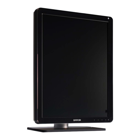
Table of contents
5.4 Configuration menu...........................................................................................29
5.4.1 Information ...............................................................................................29
5.4.2 Language.................................................................................................30
5.4.3 OSD setting ..............................................................................................30
5.4.3.1 OSD Horizontal Position ..........................................................................30
5.4.3.2 OSD Vertical Position .............................................................................30
5.4.3.3 OSD Time-out......................................................................................30
5.4.4 Recall Profile.............................................................................................31
5.4.5 Save Profile..............................................................................................31
5.5 System menu..................................................................................................32
5.5.1 Power on DVI 1..........................................................................................32
5.5.2 DVI Output ...............................................................................................32
5.5.3 Keyboard lock............................................................................................32
5.5.4 Power Saving............................................................................................33
6. Important information ........................................................................... 35
6.1 Safety information.............................................................................................35
6.2 Environmental information ...................................................................................38
6.3 Biological hazard and returns................................................................................40
6.4 Regulatory compliance information .........................................................................40
6.5 Cleaning and disinfection ....................................................................................41
6.6 Explanation of symbols.......................................................................................41
6.7 Legal disclaimer...............................................................................................43
6.8 Technical specifications ......................................................................................43
2K5902113 (451920611383) E192HSA 27/11/2017

1. Welcome!
1. WELCOME!
1.1 About the product
Overview
The Medical Grade E192HSA is a color active matrix, liquid crystal display exclusively designed for med-
ical imaging applications.
The E192HSA is part of an LCD-display product line specifically designed for medical applications. Its
wide number of features makes this product the ideal solution for Endoscopy and operating rooms. With
its sophisticated signal processing the product offers detailed, sharp, accurate, noise-free pictures, perfect
when coupled with state-of-the-art Endoscopy equipment and in spite of the different aspect ratio it also
supports Full-HD video signals.
The other key features of the E192HSA series are:
• State-of-the-art LCD screen
• Sophisticated signal processing specifically designed for low-noise, flicker-free image that minimizes
the doctor’s eye fatigue.
In addition its internal 10-bit digital signal processing provides accurate color reproduction for the de-
tection of the most subtle color changes.
• For critical operations the monitor can reduce to a minimum the picture delay typical of all the digital
displays, thus closing the gap with CRT monitors.
• Full range of analog and digital Video inputs; analog and digital computer inputs up to WUXGA. Ac-
cepted HD formats are:
- 720p (SDI, DVI-D/HDMI compatible, YPbPr)
- 1080i (SDI, DVI-D/HDMI compatible, YPbPr)
- 1080p (SDI, DVI-D/HDMI compatible, YPbPr)
• Multi-Image modality. It allows the presentation of 2 full HD images as:
- Picture-in-Picture: the secondary image is displayed in a small window.
- Side-by-Side: the screen is divided in 2 equal parts.
• RS232 Serial Interface for remote control (detailed specs available on request).
• User-selectable Gamma functions, including DICOM-like curve.
• Universal mounting (VESA 100).
• Easy cleaning thanks to chemical resistant front surface (Protection screen).
• Luminance and grayscale stability versus viewing angle.
Model identification
The monitor described in this manual, has been certified and registered by the safety agencies & regula-
tory authorities under the model number: MED19OR
1.2 What’s in the box
Overview
Your E192HSA display comes with:
K5902113 (451920611383) E192HSA 27/11/2017 3

1. Welcome!
• E192HSA user guide
•DVIcable
• AC power cords
• external power supply
• 4 screws, 4 dented washers and an Allen key
Keep your original packaging. It is designed for this display and is the ideal protection
during transport.
4K5902113 (451920611383) E192HSA 27/11/2017

2. Parts, controls and connectors
2. PARTS, CONTROLS AND
CONNECTORS
2.1 Front view
Overview
1
2
3 4 5 6 7 8
Image 2-1
1. Input Selection key
2. Multi-image selection key / Down key
3. Image zoom key / Up key
4. OSD Menu key / Enter key
5. Brightness decrease / Left key
6. Brightness increase / Right key
7. Power LED
8. Stand-by key
K5902113 (451920611383) E192HSA 27/11/2017 5

2. Parts, controls and connectors
2.2 Rear view
Overview
2
3
1
Image 2-2
1. VESA mount screw holes (100 x 100 mm)
2. Connector compartment
3. Protective earth pin
2.3 Connector view
Overview
910 11 12 13 14 15 16
4 82 31 5 6 7
17
Image 2-3
1. SDI in
2. SDI out
3. VGA in
4. Sync
5. CVBS in
6. CVBS out
7. S-Video out
8. RS232
9. Power on/off switch
10. Power in
11. DVI out
12. DVI in
13. R/Pr
6K5902113 (451920611383) E192HSA 27/11/2017

2. Parts, controls and connectors
14. G/Y/SOG
15. B/Pb
16. S-Video in
17. Service
2.4 Connector pin assignments
2.4.1 Input power connector
Overview
Image 2-4
1. GND
2. Not connected
3. +24 VDC
4. GND
5. Shield
6. +24 VDC
The ground and the shield connections on the power input connector have no Protective
Earth function. A Protective Earth connection is provided via a dedicated pin (see "Rear
view", page 6 ).
2.4.2 DVI connector (DVI-D)
Overview
Image 2-5
1. D2_Rx- (T.M.D.S.)
2. D2_Rx+ (T.M.D.S.)
3. GND (data 2 shield)
4. Not connected
5. Not connected
6. SCL (for DDC)
7. SDA (for DDC)
8. Not connected
9. D1_Rx- (T.M.D.S.)
10. D1_Rx+ (T.M.D.S.)
11. GND (data 1 shield)
12. Not connected
13. Not connected
14. +5V output (*)
K5902113 (451920611383) E192HSA 27/11/2017 7

2. Parts, controls and connectors
15. GND (cable sense)
16. Hot plug detect (*)
17. D0_Rx- (T.M.D.S.)
18. D0_Rx+ (T.M.D.S.)
19. GND (data 0 shield)
20. Not connected
21. Not connected
22. GND (clock shield)
23. CK_Rx+ (T.M.D.S.)
24. CK_Rx- (T.M.D.S.)
(*) +5 VDC output selectable on either pin 14 or 16 via the OSD menu. (+5V ± 10% @ 500mA (max))
2.4.3 RS232 connector
Overview
Image 2-6
1. Not connected
2. Rx (driven by host)
3. Tx (driven by display)
4. Not connected
5. Ground
6. Not connected
7. Not connected
8. Not connected
9. Not connected
2.4.4 S-Video and S-Video-out connector
Overview
Image 2-7
1. Ground (Y)
2. Ground (C)
3. Luminance (Y)
4. Chroma (C)
5. SG: Shielded Ground
8K5902113 (451920611383) E192HSA 27/11/2017

2. Parts, controls and connectors
2.4.5 VGA connector
Overview
Image 2-8
1. R in
2. G in
3. B in
4. Ground
5. Not connected
6. Ground
7. Ground
8. Ground
9. Input power supply for DDC
10. Ground
11. Ground
12. SDA (for DDC option)
13. Horizontal sync in
14. Vertical sync in
15. SCL (for DDC option)
K5902113 (451920611383) E192HSA 27/11/2017 9

2. Parts, controls and connectors
10 K5902113 (451920611383) E192HSA 27/11/2017

3. Display installation
3. DISPLAY INSTALLATION
3.1 Interface connection
About the interfaces
The E192HSA can have multiple video inputs connected. Switching between the different inputs can be
done easily with the Source shortkey ( ).
The Picture in Picture (PiP) and Side-by-Side (SbS) functionality becomes available if more than one
video source is connected. This allows you to view two different video inputs at once. Please refer to the
dedicated chapter for more info.
Beside video inputs, the E192HSA also has video output capabilities allowing you to loop-through certain
video inputs to another display, projector, video recorder, ...
This chapter describes how to connect the different video interface types to the E192HSA.
WARNING:To maintain compliance with EMC regulation, use only shielded interface
cables for the connection to peripheral devices.
To connect the interfaces
1. Connect one or more video source(s) to the corresponding video inputs:
-1:SDI
-2:VGA
-3:CVBS
-4/5/6: R/G/B (SOG)
-4/5/6/7: R/G/B/S
-5/6/4:Y/Pb/Pr
-8: S-Video
-9:DVI
1
49 5 6 8
2 7
3
Image 3-1
2. Connect one or more of the available video sink(s) to the corresponding video outputs:
K5902113 (451920611383) E192HSA 27/11/2017 11

3. Display installation
-1:SDI
-2:DVI
-3:CVBS
-4: S-Video
1 2
3 4
Image 3-2
3.2 Power supply connection
To connect the power supply
1. Connect the supplied external DC power supply unit to the +24 VDC power input of your E192HSA
display.
2. Plug the other end of the power supply into a grounded power outlet by means of the proper power
cord delivered in the packaging.
Warning:To avoid risk of electric shock, the external DC power supply must be connected to a mains
with protective earth. The ground connection on the display’s DC power input connector has
no protective earth function. The E192HSA display protective earth connection is provided
viaadedicatepin(seenextsteps).
Image 3-3
Protective earth
Earth the E192HSA by connecting the protective earth pin to a grounded outlet by means of an AWG18
wire (maximum admitted cable length according to national regulation requirements) and screw with lock
washer M4x12 max.
Image 3-4
12 K5902113 (451920611383) E192HSA 27/11/2017

3. Display installation
3.3 VESA mount installation
To install the display on a VESA mounting solution
Attach the display to a VESA arm or stand (VESA 100 mm is supported) by making use of the included 4
screws (M4 x 25mm) and the dented washers.
Image 3-5
CAUTION:The 4 screws included (M4 x 25 mm) can be used for a VESA arm interface
with a thickness of up to 10 mm.
If, due to the thickness of the VESA arm interface (=V), the length of the provided screws
(=L) is not suitable, consider the following rule: L = V + 15 mm
CAUTION:Use an arm that is in compliance with VESA requirements.
CAUTION:The monitor VESA interface has been designed for a safety factor 6 (to sup-
port 6 times the monitor weight). In the medical system, use an arm with suitable safety
factor (IEC60601–1).
K5902113 (451920611383) E192HSA 27/11/2017 13

3. Display installation
14 K5902113 (451920611383) E192HSA 27/11/2017

4. Daily operation
4. DAILY OPERATION
4.1 Power LED
About
The behavior of the power LED shows the current status of the display:
LED behavior Display mode
Off Hard power OFF (rocker switch in position ’0’ or input power unplugged)
Steady orange Soft power OFF (switched off by using the stand-by key ( ))
Steady green Power ON and valid input signal.
Blinking orange Power save mode (backlight and LCD off).
Blinking green Power ON and searching for signal.
Note: When Power save mode is enabled, the display will automatically go into
power save mode after 10 seconds of searching without signal.
4.2 On/Off switching
To switch on your display:
1. Activate the input power by toggling the rocker switch at the back of the display to position ’I’.
2. Press and hold the stand-by key for approximately 3 seconds until the power LED turns green.
To switch off your display:
1. While your display is switched on, press and hold the stand-by key for approximately 3 seconds until
the power LED turns orange.
The front key illumination will blink while pressing the stand-by key.
Toggle the rocker switch at the back of the display to position ’0’ to minimize power
consumption.
4.3 Power save mode
About
By default, the display will go into power save mode when no valid signal is present at the selected video
input for more than 10 seconds. This will switch off the backlight and LCD and is indicated by a blinking
orange power LED.
To exit power save mode and switch the display back on, shortly press the or key.
K5902113 (451920611383) E192HSA 27/11/2017 15

4. Daily operation
Power save mode can be disables in the OSD menus. Please refer to "Power Saving",
page 33.
The display does not accept any RS-232 commands when it is in power save mode.
4.4 OSD menu activation
To activate the OSD menu
1. Press the key while your display is powered on.
2. If the OSD lock window appears, press the following keyboard sequence to unlock the OSD menu: ,
, ,
Each time a key is pressed an asterisk is shown in the square boxes.
Keyboard lock
Sequence: 5 - 6 - 6 - 3
Image 4-1
The OSD main menu comes up in the bottom right corner of the screen. If no further actions are taken
within the following 30 seconds, the OSD menu will disappear again.
The OSD lock function can be disabled to allow OSD menu access immediately from
the key without the need to enter the unlock sequence each time. Please refer to
"Keyboard lock", page 32.
The OSD menu position and the time-out of the automatic close function can be adjusted
in the OSD menu. Please refer to "OSD setting", page 30.
4.5 OSD menu navigation
OSD menu structure explained
Below is an example of the OSD menu structure:
16 K5902113 (451920611383) E192HSA 27/11/2017

4. Daily operation
Picture
Brightness 50
Contrast 50
Saturation 30
Profile Factory
Color temperature 6500K
Gamma Native
Sharpness 10
DVI 1280x800@60Hz
16
5
32 4
Image 4-2
1Menu
2Sub-menu
3Status bar
4Legend (shows the functionality associated to each keyboard key)
5Selector/Slider
6Item
To navigate through the OSD menu
Image 4-3
•Pressthekey to open the OSD menu.
•Usetheor key to scroll to the desired menu page.
• When the desired Menu page is highlighted, press the key to select the top menu item that will be
highlighted.
•Usetheor keys to move to other Menu Items, then press the key to select it.
• If the selected menu item is controlled by a slider use the or keys to adjust the item value, then
press the key to confirm.
• If the selected menu item is a multiple choices menu use the or keys to select the desired option
then press the key to confirm.
• Press again or key to select other Menu items or exit from the Menu page by pressing the key.
4.6 Shortkey functions
About shortkey functions
The concept of shortkey functions is to present a selection of commonly used functions immediately avail-
able without the need to navigate through the OSD Menu.
The different available shortkey functions are:
K5902113 (451920611383) E192HSA 27/11/2017 17

4. Daily operation
• Main source selection
•Multi-imageconfiguration
• Zoom factor selection
• Brightness adjustment
•Pictureswap
Overview of shortkeys
1
2
3 4 5 6
Image 4-4
1Main source selection
2Multi-image configuration
3Zoom factor selection
4Brightness decrease
5Brightness increase
6Picture swap
4.6.1 Main source selection
To quickly select the main source
1. Use the Input selection key ( ) to scroll through all the possible input signals to select the main input
source.
4.6.2 Multi-image configuration
To quickly select the multi-image configuration
1. Use the PiP selection key ( ) to scroll through all possible configurations of Picture-in-Picture (PiP) and
Side-by-Side (SbS).
The different PiP/SbS options are:
- Small PiP: 30% of Primary height in top-right corner
- Large PiP: 50% of Primary height in top-right corner
- Side-by-Side: Primary and Secondary input of equal height
Only a subset of multi-image configuration settings is available via this shortkey func-
tion. More multi-image configuration settings can be selected in the OSD menus.
4.6.3 Zoom factor selection
To quickly select the zoom factor
1. Use the Image zoom key ( ) to select one of the available zoom factors.
4.6.4 Brightness adjustment
To quickly adjust the brightness
1. While no OSD Menu is on the screen, press the Brightness decrease ( ) or Brightness increase ( )
keys to adjust the brightness as desired.
18 K5902113 (451920611383) E192HSA 27/11/2017
Table of contents
Other Barco Monitor manuals

Barco
Barco MFCD 1219 (TS User manual

Barco
Barco Nio 5MP User guide

Barco
Barco MDNG-5221 User manual

Barco
Barco RDDS User manual

Barco
Barco Coronis Uniti MDMC-12133 User manual

Barco
Barco B-16 Mobile LED User manual

Barco
Barco Nio 3MP User manual

Barco
Barco MDSC-1119-2124 Technical manual

Barco
Barco Eonis MDRC-2224 User manual

Barco
Barco SEER User manual

Barco
Barco RHDM-1701 User manual

Barco
Barco RHDM-2301 User manual

Barco
Barco MDRC-2124 User manual

Barco
Barco MDSC-1119 User manual

Barco
Barco LC-5621 User manual

Barco
Barco Nio systems User manual

Barco
Barco Nio Color 2MP User manual

Barco
Barco AMM215WTTP User manual

Barco
Barco Eonis MDRC-2324 User manual

Barco
Barco TX-126 User manual