Barco MDCG-5221 User manual

Coronis 5MP LED Display
User Guide
MDCG-5221
K5902120/01
18/01/2018

Barco NV
Beneluxpark 21, 8500 Kortrijk, Belgium
Phone: +32 56.23.32.11
Fax: +32 56.26.22.62
Support: www.barco.com/en/support
Visit us at the web: www.barco.com
Registered address: Barco NV
President Kennedypark 35, 8500 Kortrijk, Belgium
Phone: +32 56.23.32.11
Fax: +32 56.26.22.62
Support: www.barco.com/en/support
Visit us at the web: www.barco.com
PrintedinBelgium

Table of contents
TABLE OF CONTENTS
1. Welcome! .......................................................................................... 3
1.1 About the product ............................................................................................. 3
1.2 What’s in the box.............................................................................................. 3
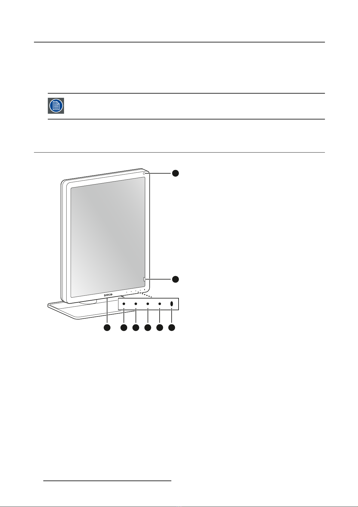
1.3 Product overview.............................................................................................. 4
2. Installation ......................................................................................... 7
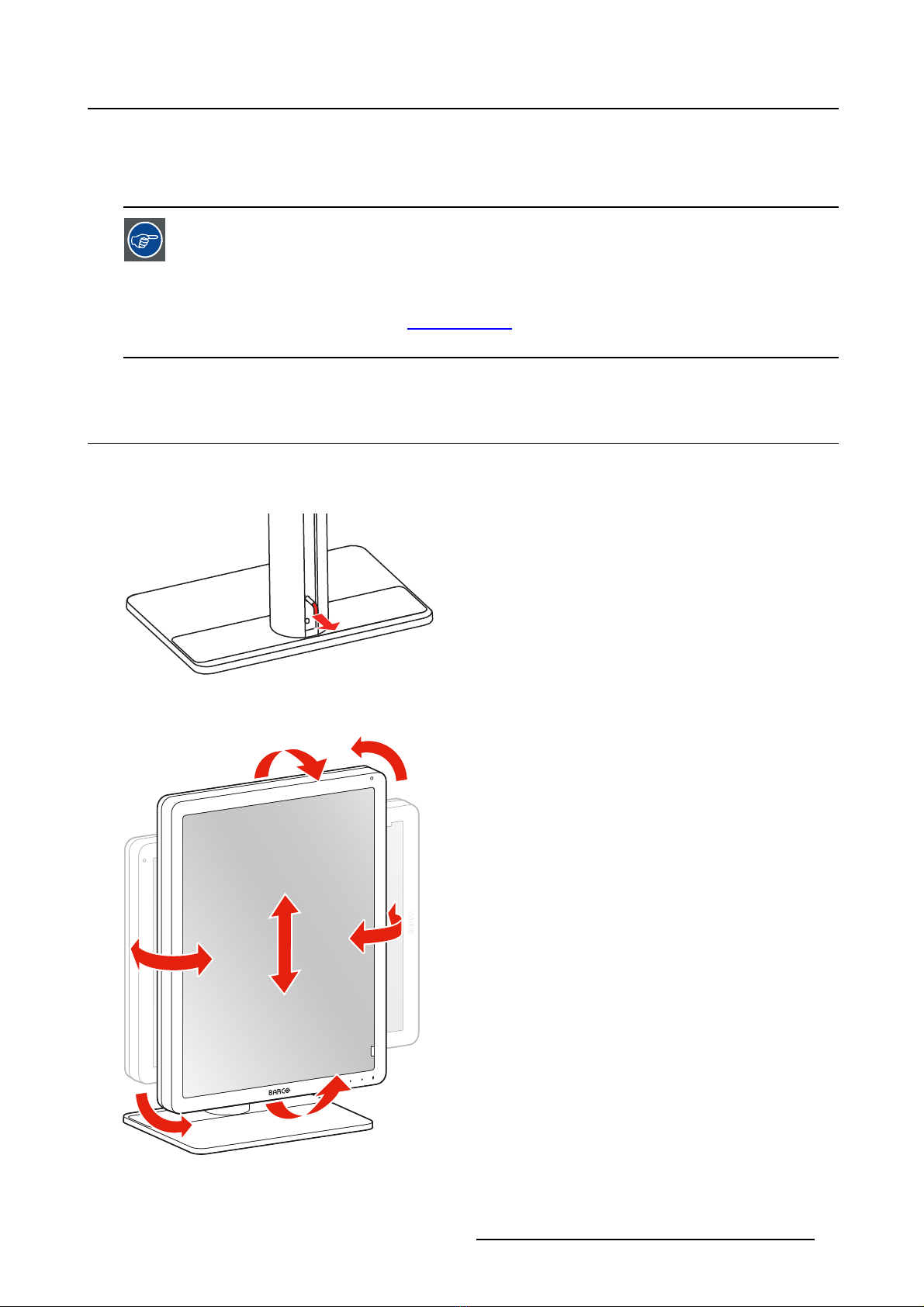
2.1 Display position adjustment.................................................................................. 7
2.2 Cable connections ............................................................................................ 8
2.3 VESA-mount installation .....................................................................................10
2.4 First time starting up..........................................................................................12
3. Daily operation ................................................................................... 13
3.1 Recommendations for daily operation ......................................................................13
3.2 Key indicator lights............................................................................................14
3.3 Standby switching.............................................................................................14
3.4 Bringing up the OSD menus .................................................................................15
3.5 Navigating through the OSD menus ........................................................................15
3.6 I-Luminate .....................................................................................................16
4. Advanced operation ............................................................................. 17
4.1 OSD menu language .........................................................................................17
4.2 OSD menu automatic close function........................................................................17
4.3 Power LED.....................................................................................................17
4.4 Key indicator lights............................................................................................18
4.5 Power lock function ...........................................................................................18
4.6 DPMS mode...................................................................................................18
4.7 Hibernate.......................................................................................................19
4.8 I-Luminate default mode .....................................................................................20
4.9 Luminance target..............................................................................................20
4.10 Viewing modes................................................................................................20
4.11 Display functions..............................................................................................21
4.12 Ambient Light Compensation (ALC) ........................................................................22
4.13 Reading rooms ................................................................................................22
4.14 Continuous ALC...............................................................................................23
4.15 Embedded QA.................................................................................................23
4.15.1 About Embedded QA ...................................................................................23
4.15.2 DICOM status report ....................................................................................24
4.15.3 DICOM compliance check..............................................................................24
4.15.4 DICOM calibration.......................................................................................25
4.15.5 Reset DICOM calibration ...............................................................................25
4.15.6 DICOM error threshold..................................................................................25
4.16 Display orientation ............................................................................................25
4.17 Video input signals............................................................................................26
4.18 Video encoding modes .......................................................................................26
4.19 Grayscale conversion modes................................................................................27
4.20 EDID timings...................................................................................................27
4.21 EDID format ...................................................................................................28
4.22 Display info ....................................................................................................28
4.23 Display status..................................................................................................29
5. Repacking instructions ......................................................................... 31
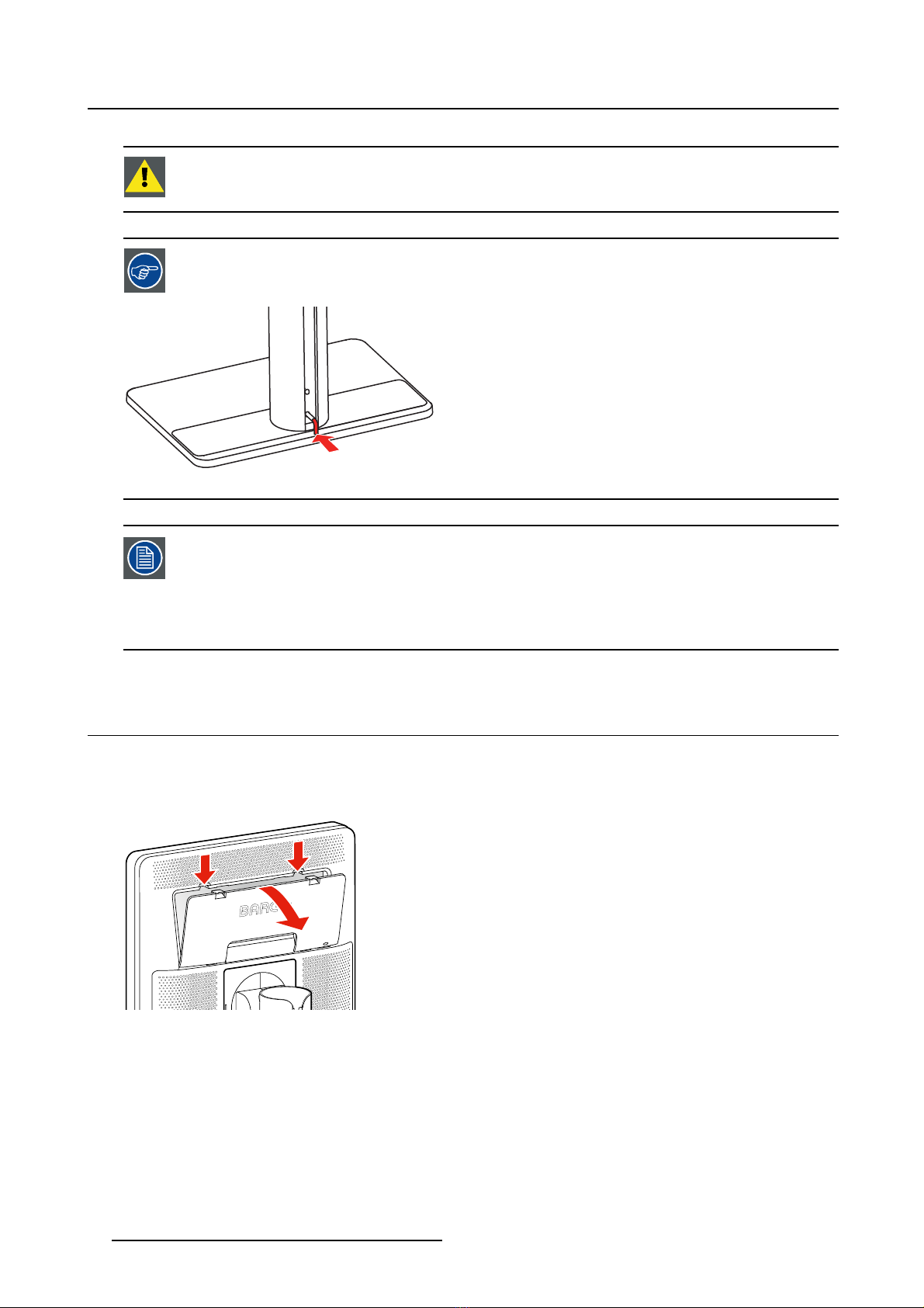
5.1 Foot protection buffer.........................................................................................31
5.2 Repacking overview ..........................................................................................32
6. Cleaning your display ........................................................................... 35
6.1 Cleaning instructions .........................................................................................35
K5902120 CORONIS 5MP LED DISPLAY 18/01/2018 1

Table of contents
7. Important information ........................................................................... 37
7.1 Safety information.............................................................................................37
7.2 Environmental information ...................................................................................39
7.3 Regulatory compliance information .........................................................................40
7.4 EMC notice ....................................................................................................41
7.5 Explanation of symbols.......................................................................................45
7.6 Legal disclaimer...............................................................................................47
7.7 Technical specifications ......................................................................................48
7.8 Open source license information ............................................................................50
2K5902120 CORONIS 5MP LED DISPLAY 18/01/2018

1. Welcome!
1. WELCOME!
1.1 About the product
Overview
Thank you for choosing this Coronis 5MP LED Display!
Coronis 5MP LED Display is the industry-leading display system for grayscale radiology imaging. It de-
livers optimum diagnostic precision and workflow efficiency for high-resolution PACS imaging, CT, MRI,
chest radiology, angiography, etc.
50 more shades of gray
Barco’s high-bright LED backlights render more Just Noticeable Differences to help you see more shades
of gray. By making subtle details more noticeable more quickly, Coronis 5MP LED Display reduceswin-
dowing and leveling time so you can read more studies each day.
Perfect images
Barco’s image-enhancing technologies — designed for the unique characteristics of LED backlit medical
displays — ensure perfect image quality at all times. PPU-LED removes panel noise and renders uniform
DICOM images from center to corner. An Intelligent Multi Sensor Technology system (I-MST) combines
Barco’s patented I-Guard front-of-screen sensor with backlight, ambient light and temperature sensors to
optimize image quality and keep it consistent over time.
Green performance
Using energy-efficient LED backlights, Barco’s Coronis 5MP LED Display is as low in power consumption
as it is high in brightness. Additionally, Barco’s LED backlights are mercury-free, produce less heat, and
last longer. This allows Barco to guarantee a 5-year backlight warranty.
Worryfree DICOM compliance
Barco’s Coronis 5MP LED Display is bundled with MediCal QAWeb for automated calibration and QA,
ensuring continuous diagnostic quality and maximum uptime of your workstation. MediCal QAWeb allows
you to continue working while automated QA checks are being executed. The system also includes a
secure online web service for remote, centralized image quality management.
I-Luminate™
One push ’hot light’ brightness boost for inspection of subtle details or comparing with film-based priors.
CAUTION:Read all the important safety information before installing and operating your
Coronis 5MP LED Display. Please refer to the dedicated chapter in this user guide.
1.2 What’s in the box
Overview
• MDCG-5221 display
• User guide
• System disc
• Documentation disc
• DisplayPort cable
• Mains cables
K5902120 CORONIS 5MP LED DISPLAY 18/01/2018 3

1. Welcome!
• External power supply
•USBcable
If you ordered a Barco display controller, it’s also in the box together with its accessories. A dedicated
user guide is available on the documentation disc.
Keep your original packaging. It is designed for this display and is the ideal protection
during transport and storage.
1.3 Product overview
Front
21 3 4 5 6
7
8
Image 1-1
1. USB-A 2.0 downstream connector
2. I-Luminate/Left key
3. Right key
4. Menu key
5. Standby key
4K5902120 CORONIS 5MP LED DISPLAY 18/01/2018

1. Welcome!
6. Power status LED
- Off: Display not powered, or display operational but power LED function disabled in OSD (see
"Power LED", page 17)
- Steady white: Display operational
- Slow blinking amber: Display in suspend mode (requires DPMS mode to be enabled in the OSD
menu, see "DPMS mode", page 18)
- Fast blinking amber: Display in standby mode (requires DPMS mode to be enabled in the OSD
menu, see "DPMS mode", page 18)
- Steady amber: Display switched off via the standby key, or display in hibernate mode (requires
DPMS mode and Hibernate to be enabled in the OSD menu, see "DPMS mode", page 18 and
"Hibernate", page 19)
7. Ambient light sensor
8. Front sensor
Back
7
6
8
9
10
51 2 3 4
Image 1-2
1. DisplayPort video input
2. DVI video input
3. USB-B 2.0 upstream connector1
4. USB-A 2.0 downstream connectors (2x)
5. +24 VDC power input
6. Connector compartment cover
7. Kensington security lock
8. VESA mount cover plate
9. Cable duct
10. Foot lock clip
1. Always connect the display(s) to a USB 3.0 hub if available. A USB 2.0 hub may be used but may not support more than two connected
displays. If insufficient USB resources are available on the PC, the USB cable may be left unattached and the display will communicate
essential QC information using DDC on the video cable, albeit more slowly; USB peripherals will also be ignored.
K5902120 CORONIS 5MP LED DISPLAY 18/01/2018 5

1. Welcome!
6K5902120 CORONIS 5MP LED DISPLAY 18/01/2018

2. Installation
2. INSTALLATION
Prior to installing your Coronis 5MP LED Display and connecting all necessary cables,
make sure to have a suitable display controller physically installed in your computer. If
you are using a Barco display controller, please consult the user guide delivered with it
to do this.
For a list of compatible display controllers, please refer to the latest version of the com-
patibility matrix available on my.barco.com (MyBarco > My Support > Healthcare > Com-
patibility Matrices > Barco Systems Compatibility Matrices).
2.1 Display position adjustment
To adjust the display position
1. Pull out the red foot lock clip from the hole at the back of the foot.
Image 2-1
2. You can now safely tilt, swivel, pivot, raise and lower the display as desired.
Image 2-2
K5902120 CORONIS 5MP LED DISPLAY 18/01/2018 7

2. Installation
WARNING:The display must be in its highest position before it can be properly pivoted.
Store the foot lock clip in the storage hole in case the display needs to be transported
later.
Image 2-3
If, after installing the display of the system, you change the panel orientation while an
image is on the screen, the result depends on the graphic board and the resolution of
the image. In some cases the image will be rotated automatically, in other cases it will
not be rotated (e.g., when pixels would be lost after rotation). If necessary, change the
image resolution in the display control panel and restart the system after changing the
orientation.
2.2 Cable connections
To connect the cables
1. Open the connector compartment. Do this by gently pushing the two lips on top of the cover, after
which it can be removed from the display.
Image 2-4
8K5902120 CORONIS 5MP LED DISPLAY 18/01/2018

2. Installation
2. Connect a video source from your workstation to the corresponding video inputs on the display.
Caution: Connect only one of the two video inputs. Connecting both inputs simultaneously will result
in driver errors.
Image 2-5
3. Connect the workstation’s USB host to the USB upstream connector on the display if you want to
make use of QAWeb or any of the display USB downstream connectors (e.g. to connect a keyboard,
mouse, touch pad or other peripheral).
Image 2-6
4. Connect the supplied external DC power supply to the power input on the display.
Image 2-7
K5902120 CORONIS 5MP LED DISPLAY 18/01/2018 9

2. Installation
5. Route all cables through the cable duct in the stand of your display. For better strain-relief and shield-
ing of the cables, fix the cables with the cable straps at the inside of the connector compartment.
Image 2-8
6. Close the connector compartment cover. You will hear a “click” sound when the cover is in position.
Image 2-9
7. Connect the external DC power supply to a grounded power outlet by using one of the power cables
included with the display.
2.3 VESA-mount installation
CAUTION:Use suitable mounting apparatus to avoid risk of injury.
WARNING:Never move a display attached to an arm by pulling or pushing the display
itself. Instead, make sure that the arm is equipped with a VESA approved handle and
use this to move the display.
Please refer to the instruction manual of the arm for more information and instructions.
10 K5902120 CORONIS 5MP LED DISPLAY 18/01/2018

2. Installation
WARNING:Use an arm that is approved by VESA (according to the VESA 100 mm stan-
dard).
Use an arm that can support the weight of the display. Refer to the technical specifica-
tions of this display for the applicable weight.
Overview
The panel, standard attached to the tilt & swivel foot, is compatible with the VESA 100 mm standard. So
itcanbeusedwithanarmstandaccordingtotheVESA100mmstandard.
Therefore, the tilt & swivel foot must be removed from the panel.
1. Put the display in the lowest position and lock the height mechanism.
Image 2-10
2. Put the display face down on a clean and soft surface. Be careful not to damage the panel screen.
3. Remove the plastic cover with a flathead screw driver.
Image 2-11
4. Slide the plastic cover over the neck of the foot.
Image 2-12
K5902120 CORONIS 5MP LED DISPLAY 18/01/2018 11

2. Installation
5. Remove the four screws fixing the foot while supporting the foot.
Image 2-13
6. Attach the arm stand firmly to the panel using 4 screws M4 x 8 mm.
2.4 First time starting up
Overview
You are now ready to start up your Coronis 5MP LED Display for the first time.
1. Switch on your Coronis 5MP LED Display as described in "Standby switching", page 14.
2. Turn on the computer connected to your display.
If you have properly installed your display and display controller, the Windows start-up messages will
appear once the boot procedure is finished.
Your Coronis 5MP LED Display will be running in a basic video mode at a default refresh
rate when first time starting up. If you are using a Barco display controller, please con-
sult the user guide delivered with it to install the drivers, software and documentation.
When this is done, your display will automatically detect the connected video input sig-
nal(s) and apply the correct video mode and refresh rate.
12 K5902120 CORONIS 5MP LED DISPLAY 18/01/2018

3. Daily operation
3. DAILY OPERATION
3.1 Recommendations for daily operation
Optimize the lifetime of your display
Enabling the Display Power Management System (DPMS) of your display will optimize its diagnostic life-
time by automatically switching off the backlight when the display is not used for a specified period of time.
By default, DPMS is enabled on your display, but it also needs to be activated on your workstation. To do
this, go to “Power Options Properties” in the “Control Panel”.
Barco recommends setting DPMS activation after 20 minutes of non-usage.
Use a screen saver to avoid image retention
Prolonged operation of an LCD with the same content on the same screen area may result in a form of
image retention.
You can avoid or significantly reduce the occurrence of this phenomenon by using a screen saver. You
can activate a screen saver in the “Display properties” window of your workstation.
Barco recommends setting screen saver activation after 5 minutes of non-usage. A
good screen saver displays moving content.
In case you are working with the same image or an application with static image elements for several hours
continuously (so that the screen saver is not activated), change the image content regularly to avoid image
retention of the static elements.
Understand pixel technology
LCD displays use technology based on pixels. As a normal tolerance in the manufacturing of the LCD, a
limited number of these pixels may remain either dark or permanently lit, without affecting the diagnostic
performance of the product. To ensure optimal product quality, Barco applies strict selection criteria for its
LCD panels.
To learn more about LCD technology and missing pixels, consult the dedicated white
papers available at www.barco.com/healthcare.
Enhance user comfort
Every Barco multi-head display system is color matched with the highest specifications in the market.
Barco recommends keeping color-matched displays together. Furthermore, it is impor-
tant to use all displays of a multi-head configuration at the same rate to preserve color
matching throughout the economic lifetime of the system.
K5902120 CORONIS 5MP LED DISPLAY 18/01/2018 13

3. Daily operation
Maximize quality assurance
The ’MediCal QAWeb’ system offers online service for high-grade Quality Assurance, providing maximum
diagnostic confidence and uptime.
Barco recommends to install MediCal QAWeb Agent and apply the default QAWeb policy
at least. This policy includes calibration on regular intervals. Connecting to MediCal
QAWeb Server offers even more possibilities.
Learn more and sign up for the free MediCal QAWeb Essential level at
www.barco.com/QAWeb.
3.2 Key indicator lights
About the key indicator lights
By default, the indicator lights of the keys will be dimmed which makes the keys unavailable at that mo-
ment. To make the keys illuminate and available for further actions touch one of the keys. As a result, all
keys will be illuminated and are now available for further actions. However, if no further actions are taken
within the following 5 seconds, the keys will dim again.
The I-Luminate/Left key is always lit and available for activation of the I-Luminate fea-
ture. Please refer to"I-Luminate", page 16 for more information.
3.3 Standby switching
About standby switching
The connected power supply also provides a switch that can be used to turn the power
completely off. To use the display, please make sure to switch on this power supply.
This can be done by pushing the on/off switch on the power supply into the “│” position.
Switching on the display while it is in standby mode or vice versa can be done by:
1. Illuminate the keys as previously described.
2. While the keys are illuminated, touch the standby key for approximately 2 seconds.
As a result, the display will switch on or will switch to standby mode.
In case of a power outage recovery, your display will always start-up in the power mode
it was in before the power interruption (i.e. standby or on). This protects your display
against inadvertent image retention problems.
14 K5902120 CORONIS 5MP LED DISPLAY 18/01/2018

3. Daily operation
3.4 Bringing up the OSD menus
How to bring up the OSD menus
TheOSDmenuallowsyoutoconfigure different settings to make your Coronis 5MP LED Display fityour
needs within your working environment. Also, you can retrieve general information about your display and
its current configuration settings through the OSD menu.
Bringing up the OSD menus can be done by:
1. If not already done so, switch on the display as previously described.
2. Illuminate the keys as previously described.
3. While the keys are illuminated, touch the menu key.
As a result, the OSD main menu comes up. However, if no further actions are taken within the following
90 seconds, the OSD will disappear again.
The OSD menu auto-exit function can be disabled in the OSD menu. Please refer to"OSD
menu automatic close function", page 17 for detailed instructions on how to do this.
3.5 Navigating through the OSD menus
How to navigate through the OSD menus
Navigating through the OSD menus can be done by:
• Use the left/right keys to move through the (sub)menus, change values or make selections.
• To go into a submenu or confirm adjustments and selections, use the menu key.
• Use the standby key to cancel adjustments or exit a (sub)menu.
• Exit all OSD menus at once by touching the standby key for approximately 2 seconds.
The key icons are displayed above the keys, adapted to the function that it is used for
(menu dependent).
I-Luminate is not available while the OSD menu is activated.
Overview key icons
Left, Right
Menu
Enter
K5902120 CORONIS 5MP LED DISPLAY 18/01/2018 15

3. Daily operation
Cancel
Standby (IEC 60417–5009)
3.6 I-Luminate
About I-Luminate
When the display is in power on mode and the OSD menu is not shown, I-Luminate can be activated by
touching the I-luminate/left key.
Unlike other Barco products, especially designed for tomography, in the MDCG-5221, I-Luminate supports
one mode: Full-screen luminance boost.
When touching the I-Luminate key, the display will enter the I-Luminate mode, for approximately 1 minute.
Touch the I-Luminate key again to immediately switch back to normal mode.
16 K5902120 CORONIS 5MP LED DISPLAY 18/01/2018

4. Advanced operation
4. ADVANCED OPERATION
4.1 OSD menu language
About the OSD menu language
By default, the OSD menu comes up in English. However, there’s a wide range of other languages avail-
able for the OSD menu of your Coronis 5MP LED Display.
To change the language of the OSD menu:
1. Bring up the OSD main menu.
2. Navigate to the Configuration > User Interface > Menu menu.
3. Enter the Language submenu.
4. Select one of the available languages and confirm.
4.2 OSD menu automatic close function
About the OSD menu automatic close function
By default, the OSD menu will disappear automatically after approximately 90 seconds of inactivity. How-
ever, this function can be disabled so that the OSD menu remains on the screen until manually closed.
To enable/disable the OSD menu automatic close function:
1. Bring up the OSD main menu.
2. Navigate to the Configuration > User Interface > Menu menu.
3. Enter the Automatic Close submenu.
4. Select Enabled/Disabled as desired and confirm.
4.3 Power LED
About the power LED
To prevent distractions, the power LED is dimmed by default when the display is switched on and used in
normal operation. This behavior can be changed so that the power LED will light up during normal oper-
ation. Below is an overview of the different power LED states, in ascending order of power consumption:
Display status Power LED behavior
Off2Dimmed
Hibernate3/Softoff
4Steady amber
Suspend mode5Slow blinking amber
Standby mode5Fast blinking amber
Dimmed (power LED disabled in OSD, default setting)
Normal operation
Steady white (power LED enabled in OSD)
2. Power supply unplugged or switched off.
3. Requires DPMS mode and Hibernate to be enabled in the OSD menu.
4. Switched off via the standby touch key.
5. Requires DPMS mode to be enabled in the OSD menu.
K5902120 CORONIS 5MP LED DISPLAY 18/01/2018 17

4. Advanced operation
To enable/disable the power LED:
1. Bring up the OSD main menu.
2. Navigate to the Configuration > User Interface > Indicator Lights menu.
3. Enter the Power Status submenu.
4. Select Enabled/Disabled as desired and confirm.
4.4 Key indicator lights
About the key indicator lights
By default, after lighting up, the key indicator lights will dim again if no further actions are taken within the
following 5 seconds. However, this behavior can be changed so that the key indicator lights are always
on or always off.
To configure the key indicator lights
1. Bring up the OSD main menu.
2. Navigate to the Configuration > User Interface > Indicator Lights menu.
3. Enter the Keys submenu.
4. Select Automatic/Always On/Always Off as desired and confirm.
The I-Luminate key is always lit and cannot be turned off.
4.5 Power lock function
About the power lock function
By enabling the power lock function, the Coronis 5MP LED Display is forced to remain switched on. This
means that it can’t be switched to stand-by mode manually until the power lock function is disabled again.
To enable/disable the power lock function:
1. Bring up the OSD main menu.
2. Navigate to the Configuration > User Interface > Controls menu.
3. Enter the Power Lock submenu.
4. Select Enabled/Disabled as desired and confirm.
4.6 DPMS mode
About DPMS mode
Enabling the Display Power Management System (DPMS) mode on your display will optimize its diagnos-
tic lifetime by automatically switching off the backlight when the display is not used for a specified period
of time. By default, DPMS mode is enabled on your display, but it also needs to be activated on your
workstation. To do this, go to the “Power options properties” window of your workstation.
18 K5902120 CORONIS 5MP LED DISPLAY 18/01/2018
Other manuals for MDCG-5221
1
Table of contents
Other Barco Monitor manuals

Barco
Barco SLite 10 XP User manual

Barco
Barco Color Coronis 2MP Manual

Barco
Barco MDMG-5221 Owner's manual

Barco
Barco ILite 10 MD User manual

Barco
Barco MDSC-2242 User manual

Barco
Barco MDSC-2326 MNAH User manual

Barco
Barco OverView EVD4621 Owner's manual

Barco
Barco OV-508 User manual

Barco
Barco DB-220 User manual

Barco
Barco MFCD-1219 User manual

Barco
Barco Coronis MDCC 2121 User manual

Barco
Barco Coronis 5MP Mammo User manual

Barco
Barco XDS-1000 User manual

Barco
Barco B-10 User manual

Barco
Barco NX--4 Manual

Barco
Barco MDSC-8532 User manual

Barco
Barco TX-126 User manual

Barco
Barco ILite 10 MD User manual

Barco
Barco LCN-47 User manual

Barco
Barco MDNC-2221 User manual