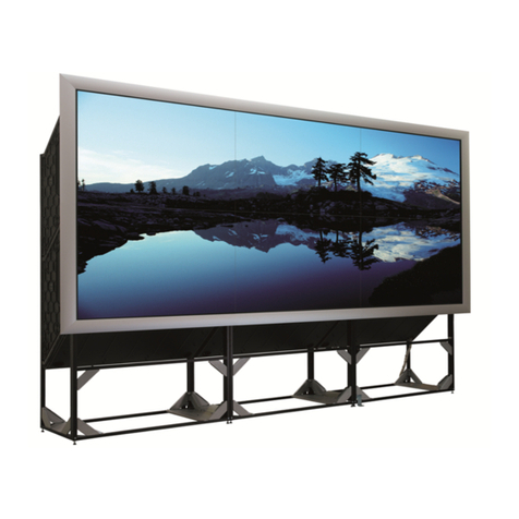
Barco Solaris LC40 R9004120 User manual

MEDIA &EVENTS
SOLARIS LC40
R9004120 (Events)
R9004125 (Media)
OWNERS MANUAL
01122003 R5976672/00

Barco nv Media
Noordlaan 5, 8520 Kuurne
Phone: +32 56.36.89.70
Fax: +32 56.36.88.24
E-mail: [email protected]
Visit us at the web: www.barco.com
Barco nv Events
Noordlaan 5, B-8520 Kuurne
Phone: +32 56.36.89.70
Fax: +32 56.36.88.24
E-mail: [email protected]
Visit us at the web: www.barco.com
Printed in Belgium

Changes
Barco provides this manual ’as is’ without warranty of any kind, either expressed or implied, including but not limited to the implied war-
ranties or merchantability and fitness for a particular purpose. Barco may make improvements and/or changes to the product(s) and/or the
program(s) described in this publication at any time without notice.
This publication could contain technical inaccuracies or typographical errors. Changes are periodically made to the information in this
publication; these changes are incorporated in new editions of this publication.
Copyright ©
All rights reserved. No part of this document may be copied, reproduced or translated. It shall not otherwise be recorded, transmitted or
stored in a retrieval system without the prior written consent of BARCO.
Trademarks
Brand and product names mentioned in this manual may be trademarks, registered trademarks or copyrights of their respective holders.
All brand and product names mentioned in this manual serve as comments or examples and are not to be understood as advertising for
the products or their manufactures.


Table of contents
TABLE OF CONTENTS
1. Packaging and Dimensions ....................................................................................... 3
1.1 Box content.............................................................................................................................. 3
1.2 Packaging............................................................................................................................... 3
1.3 Dimensions.............................................................................................................................. 4
2. Installation Guidelines.............................................................................................. 7
2.1 General . . . ............................................................................................................................... 7
2.2 Solaris LC40 configurations ............................................................................................................ 7
2.3 Battery Insertion in the Remote Control................................................................................................ 8
3. Connections.......................................................................................................... 9
3.1 Power connection . . . .................................................................................................................... 9
3.2 Input source connections . . . ............................................................................................................ 9
3.2.1 Input facilities . .................................................................................................................... 9
3.2.2 Digital Visual Interface (DVI) input . . ............................................................................................10
3.2.3 RGB analog input ...............................................................................................................12
3.2.4 Serial Digital Interface...........................................................................................................13
3.2.5 Compact PC module . ...........................................................................................................13
3.2.6 Video input module . . . ...........................................................................................................14
3.2.7 DVI input module (optional) . ....................................................................................................16
3.2.8 HD-SDI input module (optional). ................................................................................................17
3.2.9 RGB input module (optional) ....................................................................................................17
3.2.10Audio pré-amp input (optional) . ................................................................................................18
3.3 RGB out at native screen resolution (WXGA).........................................................................................18
3.4 Communication Connections . . . . . . ....................................................................................................19
3.4.1 RS232 IN/OUT ..................................................................................................................19
3.4.2 LAN connection. . . ...............................................................................................................19
3.5 Cable cover ............................................................................................................................20
4. Getting Started......................................................................................................23
4.1 Terminology overview RCU............................................................................................................23
4.2 Switching ON/OFF.....................................................................................................................24
4.3 Using the RCU .........................................................................................................................25
4.4 LCD panel address . ...................................................................................................................26
4.4.1 IR address.......................................................................................................................26
4.4.2 Displaying and Programming IR addresses into the RCU . .. ..................................................................26
4.4.3 RS232 address..................................................................................................................26
4.4.4 Controlling the Solaris LC40 with the RCU.....................................................................................26
4.5 Locking the Solaris LC40 for IR signals . . . ............................................................................................28
5. Getting used with the Menu Structure..........................................................................29
5.1 How to start up the menus.............................................................................................................29
5.2 Using the menus.......................................................................................................................29
5.3 Adjusting a control in a Slider box ....................................................................................................30
6. Input Selection......................................................................................................31
6.1 Start up the Input Selection. ...........................................................................................................31
6.2 Selecting an Input Source . . ...........................................................................................................32
6.3 Configuring input 2 . . ...................................................................................................................32
6.4 Selecting Compact PC.................................................................................................................32
7. Image Settings......................................................................................................35
7.1 Image Settings Menu overview........................................................................................................35
7.2 Aspect Ratio............................................................................................................................35
7.3 Brightness..............................................................................................................................36
7.4 Contrast ................................................................................................................................37
7.5 Color Saturation........................................................................................................................37
7.6 Tint (hue) . ..............................................................................................................................38
7.7 Sharpness ..............................................................................................................................38
7.8 Viewport ................................................................................................................................39
7.8.1 About Viewport . . . ...............................................................................................................39
7.8.2 Viewport creation................................................................................................................40
7.8.3 Automatic Viewport function ....................................................................................................43
7.8.4 Total pixels setup................................................................................................................43
7.9 Phase...................................................................................................................................44
8. Audio Settings ......................................................................................................47
8.1 Audio settings menu overview.........................................................................................................47
8.2 Starting up the audio controls .........................................................................................................47
8.3 Volume control ......................................................................................................................... 48
8.4 Balance control.........................................................................................................................48
8.5 Bass control............................................................................................................................48
8.6 Treble control...........................................................................................................................49
R5976672 SOLARIS LC40 01122003 1
Table of contents
8.7 Subwoofer control......................................................................................................................49
9. Compact PC Control...............................................................................................51
9.1 Display control by Compact PC .......................................................................................................51
10.Advanced Settings.................................................................................................53
10.1Advanced Settings menu overview ...................................................................................................53
10.2Gamma ................................................................................................................................53
10.3Color Temperature.....................................................................................................................54
10.4Input Balance ..........................................................................................................................55
10.4.1Introduction to Input Balance . . . ................................................................................................55
10.4.2Adjusting the input balance.....................................................................................................57
10.5Noise Reduction . . . . ...................................................................................................................58
10.6Display Settings .......................................................................................................................59
10.6.1Rotate ...........................................................................................................................59
10.6.2Backlight......................................................................................................................... 60
10.7Installation .............................................................................................................................61
10.7.1File Services.....................................................................................................................61
10.7.1.1Introduction to image files ................................................................................................61
10.7.1.2Load file set up ...........................................................................................................61
10.7.1.3Loading a specific file. ....................................................................................................62
10.7.2When no Signal . . ...............................................................................................................62
10.8Service.................................................................................................................................64
10.8.1Identification screen. . ...........................................................................................................64
10.8.2IR address.......................................................................................................................64
10.8.3Serial communication...........................................................................................................65
10.8.3.1RS232 address ...........................................................................................................65
10.8.3.2Changing the baudrate for RS232 communication ......................................................................66
10.8.4IR locking........................................................................................................................66
10.8.4.1Locking the display .......................................................................................................67
10.8.4.2Changing your PIN code . ................................................................................................67
10.8.5Restore Factory Defaults .......................................................................................................68
A. Standard Source Set up Files ....................................................................................69
A.1 Table overview .........................................................................................................................69
B. Optional Mounting Equipment ...................................................................................71
B.1 Wall Mounting Support. . ...............................................................................................................71
B.2 Table mounting support . ...............................................................................................................72
Glossary .................................................................................................................75
Index......................................................................................................................77
2R5976672 SOLARIS LC40 01122003

1. Packaging and Dimensions
1. PACKAGING AND DIMENSIONS
Overview
• Box content
• Packaging
• Dimensions
1.1 Box content
Content
Standard delivered for :
R9004120 R9004125
• 1 Solaris LC40 (weight : 24.5 kg)
• 2 power cables with outlet plug type CEE7 and ANSI
73.11
• 1 owners manual
• 1 remote control
• 1 video input
• 1 Solaris LC40 (weight : 24.5 kg)
• 2 power cables with outlet plug type CEE7 and ANSI
73.11
• 1 owners manual
CEE7
European power plug to connect the power cord to the wall outlet.
ANSI 73.11
American power plug to connect the power cord to the wall outlet.
1.2 Packaging
Way of Packaging
The Solaris LC40 is packed in a carton box. To provide protection during transportation, the Solaris LC40 is surrounded with foam.
The packaging is secured with banding and fastening clips.
To unpack
1. Release the fastening clips.
2. Remove the banding.
3. Take the Solaris LC40 out of its shipping carton.
Save the original shipping carton and packing material, they will be necessary if you ever have to ship your
panel. For maximum protection, repack your panel as it was originally packed at the factory.
R5976672 SOLARIS LC40 01122003 3

1. Packaging and Dimensions
1.3 Dimensions
Front view
863
950
452.5
518.25
610
Image 1-1
Front view
Back view
950
234
100
610
Image 1-2
Back view
4R5976672 SOLARIS LC40 01122003

1. Packaging and Dimensions
Bottom view
107
Image 1-3
Bottom view
R5976672 SOLARIS LC40 01122003 5

1. Packaging and Dimensions
6R5976672 SOLARIS LC40 01122003

2. Installation Guidelines
2. INSTALLATION GUIDELINES
Overview
• General
• Solaris LC40 configurations
• Battery Insertion in the Remote Control
2.1 General
Environmental conditions
• Operating temperature : 5° to 40°C (41° to 104°F)
• Humidity : max 85%
2.2 Solaris LC40 configurations
Different configurations
The Solaris LC40 can be used in two different configurations, landscape and portrait.
The portrait configuration is only possible with the optional Rotator module (order number : R9842362)
Image 2-1
Landscape configuration
Image 2-2
Portrait configuration
When using in landscape, the infra red receiver must be in the lower left corner.
When using in portrait, the infra red receiver must be in the upper left corner.
Applications
The Solaris LC40 can be used as stand alone display or as part of a network of displays.
R5976672 SOLARIS LC40 01122003 7

2. Installation Guidelines
2.3 Battery Insertion in the Remote Control
Where to find the batteries
The batteries are not placed in the remote control to avoid remote control operation in its package, resulting in a shorter battery life
time.
How to install the batteries
1. Push the cover tab (A) with the fingernail a little backwards and pull upwards the cover top (B). (image 2-3)
2. Slide the cover forwards to remove. (image 2-4)
3. Push the battery body towards the spring and lift it up to remove. (image 2-5)
4. Insert two AA size batteries, making sure the polarities match the + and – marks inside the battery compartment (image 2-5).
5. Insert the lower tab of the battery cover in the gap at the bottom of the remote control, and press the cover until it clicks in place
(image 2-4).
Image 2-3
Battery cover unlock
Image 2-4
Battery cover removal
Image 2-5
Battery removal
8R5976672 SOLARIS LC40 01122003

3. Connections
3. CONNECTIONS
Overview
• Power connection
• Input source connections
• RGB out at native screen resolution (WXGA)
• Communication Connections
• Cable cover
3.1 Power connection
AC power (mains) cord connection
Use the supplied power cord to connect your LCD panel to the wall outlet.
Plug the female power connector into the male connector at the back of the LCD panel.
The power input is auto-ranging from 90 to 240 VAC.
3.2 Input source connections
Overview
• Input facilities
• Digital Visual Interface (DVI) input
• RGB analog input
• Serial Digital Interface
• Compact PC module
• Video input module
• DVI input module (optional)
• HD-SDI input module (optional)
• RGB input module (optional)
• Audio pré-amp input (optional)
3.2.1 Input facilities
Input panel view
DVI
RGB out (1280x768)
RGB HV
RS232
OUT IN
LAN RGB analog
RGBHVINOUT
SDI
ABCD E
Image 3-1
Input panel view
Overview standard available inputs
Ref Input connector Source
ADVI DVI digital
DVI analog
R5976672 SOLARIS LC40 01122003 9

3. Connections
Ref Input connector Source
BRGB analog (BNC) RGB
CSDI SDI
Overview optional inputs
Ref Input slot Input module Source
DUniversal input for data sources DVI input DVI digital
DVI analog
RGB input RGB
HD-SDI input HD-SDI
Audio input Audioin(L+R),audioout(L+R+
Subwoofer)
EVideo sources Video input Video
S-Video
Component video
RGB Video (15 kHz)
3.2.2 Digital Visual Interface (DVI) input
DVI
Digital Visual Interface is a display interface developed in response to the proliferation of digital flat panel displays. It
uses a high speed serial interface with TMDS (Transition Minimized Differential Signaling) to send data to the display.
DVI can be single or dual link.
Input specifications
DVI
RGB out (1280x768)
RGBHV
RS232
OUT IN
LAN RGB analog
RGBHVINOUT
SDI
DVI
x768)
HV RG
Image 3-2
Standard DVI input
Pixel clock : 25 .. 165 MHz
Horizontal sync range : 15 .. 110 kHz
Vertical sync range : 23 .. 125 Hz
Max. input format : UXGA (1600x1200) @ 60 Hz
10 R5976672 SOLARIS LC40 01122003

3. Connections
DVI-Digital
• Single link
• Differential input voltage : 200mV - 800mV
DVI-Analog
• RGB input = 0.7 Vpp ±3dB
• TTL sync input : Umin =2.5V
Pin assignment for the DVI connector.
Pin 1 TMDS DATA2- Pin 15 Ground (for +5V)
Pin 2 TMDS DATA2+ Pin 16 Hot Plug Detect
Pin 3 TMDS DATA2/4 Shield Pin 17 TMDS DATA0-
Pin 4 TMDS DATA4- Pin 18 TMDS DATA0+
Pin 5 TMDS DATA4+ Pin 19 TMDS DATA0/5 Shield
Pin 6 DDC Clock Pin 20 TMDS DATA5-
Pin 7 DDC Data Pin 21 TMDS DATA5+
Pin 8 Analog Vert sync Pin 22 TMDS Clock Shield
Pin 9 TMDS DATA1- Pin 23 TMDS Clock+
Pin 10 TMDS DATA1+ Pin 24 TMDS Clock-
Pin 11 TMDS DATA1/3 Shield C1 Analog Red
Pin 12 TMDS DATA3- C2 Analog Green
Pin 13 TMDS DATA3+ C3 Analog Blue
Pin14 +5Power C4 Analog Hor Sync
C5 Ground
How to select the DVI input via the RCU?
1. Press 7on the RCU.
The internal system detects automatically the DVI source. If at the same time a digital DVI and analog DVI source is connected
and switched on, the digital DVI source will be displayed.
How to select the DVI input via the menu structure?
1. Press on the thumb wheel or press ENTER on the RCU to activate the menus.
The main menu will be displayed on the screen. (menu 3-1)
2. Turn the thumb wheel or use the up or down arrow keys to select Input selection.
The input selection menu will be displayed. (menu 3-2)
3. Turn the thumb wheel or use the up or down arrow keys to select 7DVI.
4. Press the thumb wheel or press ENTER on the RCU.
The internal system detects automatically the DVI source. If at the same time a digital DVI and analog DVI source is connected
and switched on, the digital DVI source will be displayed.
Main Menu
Input selection
Image settings
Audio settings
Compact PC Control
Advanced settings
Installation
Service
Standby
Back
Menu 3-1
Input Selection
1. Video
2. RGB
3. S-Video
4. HD-SDI/DVI/Audio/RGB
5. SDI
6. RGB
7. DVI
8. Compact PC
Configure input 2
Back
Menu 3-2
R5976672 SOLARIS LC40 01122003 11

3. Connections
3.2.3 RGB analog input
Input specifications
DVI
RGB out (1280x768)
RGBHV
RS232
OUT IN
LAN RGB analog
RGBHVINOUT
SDI
RGB analog
RGB HVINOUT
SDI
Image 3-3
RGB analog input
Pixel clock : 20 .. 165 MHz
Horizontal sync range : 15 .. 110 kHz
Vertical sync range : 23 Hz .. 125 Hz
Max input format : UXGA (1600x1200) @ 60 Hz
RGBHV inputs : 0.7Vpp ±3 dB
Possible input sources
Inputs
RGB H V
RGBHV RGB H V
RGBS RGBS-
RGB inputs
RGsBRGsB- -
How to select the RGB source via the RCU?
1. Press 6on the RCU.
The system scans the RGB analog input for a RGB input signal and detects automatically the sync.
How to select the RGB source via the menu structure
1. Press on the thumb wheel or press ENTER on the RCU to activate the menus.
The main menu will be displayed on the screen. (menu 3-3)
2. Turn the thumb wheel or use the up or down arrow keys to select Input selection.
The input selection menu will be displayed. (menu 3-4)
3. Turn the thumb wheel or use the up or down arrow keys to select 6RGB.
4. Press the thumb wheel or press ENTER on the RCU.
The internal system detects automatically the sync position (separate sync or sync on green).
Main Menu
Input selection
Image settings
Audio settings
Compact PC Control
Advanced settings
Installation
Service
Standby
Back
Menu 3-3
Input Selection
1. Video
2. RGB
3. S-Video
4. HD-SDI/DVI/Audio/RGB
5. SDI
6. RGB
7. DVI
8. Compact PC
Configure input 2
Back
Menu 3-4
12 R5976672 SOLARIS LC40 01122003

3. Connections
3.2.4 Serial Digital Interface
Specifications
DVI
RGB out (1280x768)
RGB HV
RS232
OUT IN
LAN RGB analog
RGBHVINOUT
SDI
RGB analog
BHVINOUT
SDI
Image 3-4
SDI input
SMPTE259M compatible serial digital signals only.
SDI input : BNC
SDI output : BNC (= loop through)
Typical : 0.8 Vpp
75 Ωterminated
Output impedance : 75 Ω
How to select the SDI input with the RCU?
1. Press 5on the RCU
How to select the SDI input via the menu structure?
1. Press on the thumb wheel or press ENTER on the RCU to activate the menus.
The main menu will be displayed on the screen. (menu 3-5)
2. Turn the thumb wheel or use the up or down arrow keys to select Input selection.
The input selection menu will be displayed. (menu 3-6)
3. Turn the thumb wheel or use the up or down arrow keys to select 5SDI.
4. Press the thumb wheel or press ENTER on the RCU.
Main Menu
Input selection
Image settings
Audio settings
Compact PC Control
Advanced settings
Installation
Service
Standby
Back
Menu 3-5
Input Selection
1. Video
2. RGB
3. S-Video
4. HD-SDI/DVI/Audio/RGB
5. SDI
6. RGB
7. DVI
8. Compact PC
Configure input 2
Back
Menu 3-6
3.2.5 Compact PC module
Overview
The compact PC module is internally connected display. No external source connections are necessary. When input 8 is selected,
the compact PC image will be displayed on the screen.
How to select with the RCU.
1. Press 8on the RCU
R5976672 SOLARIS LC40 01122003 13

3. Connections
How to select the Compact PC via the menu structure?
1. Press on the thumb wheel or press ENTER on the RCU to activate the menus.
The main menu will be displayed on the screen. (menu 3-7)
2. Turn the thumb wheel or use the up or down arrow keys to select Input selection.
The input selection menu will be displayed. (menu 3-8)
3. Turn the thumb wheel or use the up or down arrow keys to select 8 Compact PC.
4. Press the thumb wheel or press ENTER on the RCU.
Main Menu
Input selection
Image settings
Audio settings
Compact PC Control
Advanced settings
Installation
Service
Standby
Back
Menu 3-7
Input Selection
1. Video
2. RGB
3. S-Video
4. DVI
5. SDI
6. RGB
7. DVI
8. Compact PC
Configure input 2
Back
Menu 3-8
3.2.6 Video input module
Specifications
PAL B, G, D, H, I and N, combination PAL N, PAL M, NTSC M, NTSC-Japan, NTSC 4.43 and SECAM
Video : 1 Vpp ± 3dB
S-Video : Y= 1 Vpp ± 3dB, C = 300mVpp
CrYCbHV inputs : -0.5Vpp to 0.5Vpp
Possible inputs
Y/C C
R
YC
B
VV
IN OUT
IN
VIDEO
Image 3-5
Video input module
Inputs
Y/Cin CrYCbVin Vout
RGBS –RGBS–
RGB inputs
(15 kHz) RGsB–RGsB– –
CrYCbS–CrYCbS–
Component
inputs
CrYsCb–Cr YsCb – –
Video Composite
Video
– – – – Video –
S-Video S-Video S-Video – – – – –
14 R5976672 SOLARIS LC40 01122003

3. Connections
Pin configuration 4 pin connector
View on input module :
4
3
1
2
Image 3-6
For S-Video For Video
pin 1 : earth (ground) luminance pin 1 : earth (ground) video Y
pin 2 : earth (ground) chrominance pin 2 : earth (ground) video C
pin 3 : luminance signal (Y) 1Vpp ±3dB pin 3 : video Y signal
pin 4 : chrominance signal (C) 300mVpp pin 4 : video C signal
Chrominance
The color component of a video signal that includes information about tint and saturation.
Luminance
The component of a video signal that includes information about its brightness.
How to configure the input 2
1. Press on the thumb wheel or press ENTER on the RCU to activate the menus.
The main menu will be displayed on the screen. (menu 3-9)
2. Turn the thumb wheel or use the up or down arrow keys to select Input Selection.
The input selection menu will be displayed. (menu 3-10)
3. Turn the thumb wheel or use the up or down arrow keys to select Configure input 2.
The configuration window will be displayed. (menu 3-11)
4. Turn the thumb wheel or use the up or down arrow keys to select the corresponding input.
YUV CrYsCbsource
SYUV CrYCbS source
Main Menu
Input selection
Image settings
Audio settings
Compact PC Control
Advanced settings
Installation
Service
Standby
Back
Menu 3-9
Input Selection
1. Video
2. RGB
3. S-Video
4. HD-SDI/DVI/Audio/RGB
5. SDI
6. RGB
7. DVI
8. Compact PC
Configure input 2
Back
Menu 3-10
Configuration Input 2
YUV
SYUV
SRGB
RGsB
BACK
Menu 3-11
How to select an input via the RCU
1. For video : press 1on the RCU.
For Component/RGB input : press 2on the RCU.
For S-Video : press 3on the RCU.
R5976672 SOLARIS LC40 01122003 15

3. Connections
How to select an input via the menu structure
1. Press on the thumb wheel or press ENTER on the RCU to activate the menus.
The main menu will be displayed on the screen. (menu 3-12)
2. Turn the thumb wheel or use the up or down arrow keys to select Input selection.
The input selection menu will be displayed. (menu 3-13)
3. Turn the thumb wheel or use the up or down arrow keys to select the corresponding input (Video or S-Video or Component).
4. Press the thumb wheel or press ENTER on the RCU.
Main Menu
Input selection
Image settings
Audio settings
Compact PC Control
Advanced settings
Installation
Service
Standby
Back
Menu 3-12
Input Selection
1. Video
2. RGB
3. S-Video
4. HD-SDI/DVI/Audio/RGB
5. SDI
6. RGB
7. DVI
8. Compact PC
Configure input 2
Back
Menu 3-13
Loop through connection for Video
The composite video input (Vin) is connected in loop through with the Vout. This signal can be used to connect to the next device.
3.2.7 DVI input module (optional)
Specifications
As this module has the same specifications as the standard DVI input, Digital Visual Interface (DVI) input, page 10 for the further
specifications.
The optional input is automatically detected by the system and correctly filled out in the menu structure.
How to select with the RCU.
1. Press 4on the RCU
How to select the DVI input via the menu structure?
1. Press on the thumb wheel or press ENTER on the RCU to activate the menus.
The main menu will be displayed on the screen. (menu 3-14)
2. Turn the thumb wheel or use the up or down arrow keys to select Input selection.
The input selection menu will be displayed. The correct input will be filled out immediately in input selection 4. (menu 3-15)
3. Turn the thumb wheel or use the up or down arrow keys to select 4DVI.
4. Press the thumb wheel or press ENTER on the RCU.
Main Menu
Input selection
Image settings
Audio settings
Compact PC Control
Advanced settings
Installation
Service
Standby
Back
Menu 3-14
Input Selection
1. Video
2. RGB
3. S-Video
4. DVI
5. SDI
6. RGB
7. DVI
8. Compact PC
Configure input 2
Back
Menu 3-15
16 R5976672 SOLARIS LC40 01122003
This manual suits for next models
2
Table of contents
Other Barco Monitor manuals

Barco
Barco LDX46 User manual

Barco
Barco Nio Color 2MP User manual

Barco
Barco Encore User manual

Barco
Barco OV-508 User manual

Barco
Barco T-20 User manual

Barco
Barco Nio Color 2MP User manual

Barco
Barco DM-1126 User manual

Barco
Barco MDNG-6221 User manual

Barco
Barco Nio Fusion12MP User manual

Barco
Barco E-2320 C User manual

Barco
Barco SEER User manual

Barco
Barco Nio 2MP LED User manual

Barco
Barco Coronis 3MP LED MDCG-3221 User manual

Barco
Barco iTraffic User manual

Barco
Barco MDSC-8258 User manual

Barco
Barco MDSC-2326 MNAH User manual

Barco
Barco Solaris LD 120-8 Supplement

Barco
Barco NX--4 User manual

Barco
Barco FlexiVision III User manual

Barco
Barco IMAGETILE User guide