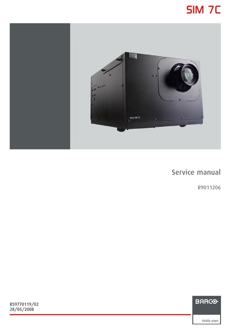
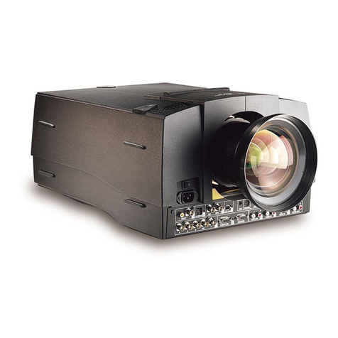
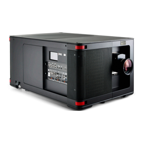
Barco Cine 5 User manual

BARCO PROJECTION SYSTEMS
Date : 18042000 Rev : 01 Art. No. : R5976101
R9002410
R9002419
OWNER'S MANUAL
CINE 5

Due to constant research, the information in this manual is subject to change without notice.
Produced by BARCO N , April, 2000
All rights reserved.
Trademarks are the rights of their respective owners.
BARCO n.v./Projection Systems
Noordlaan 5
B-8520 Kuurne
Belgium
Tel : +32/56/368211
Fax : +32/56/351651
isite Barco at the web : http://www.barco.com
Printed in Belgium
Federal communication commission (FCC statement)
This equipment has been tested and found to comply with the limits for a class A digital device, pursuant to Part 15 of the FCC
Rules and EN55022. These limits are designed to provide reasonable protection against harmful interference when the equipment
is operated in a commercial environment. This equipment generates, uses, and can radiate radio frequency energy and, if not
installed and used in accordance with the instruction manual, may cause harmful interference to radio communications. Operation
of this equipment in a residential area is likely to cause harmful interference in which case the user will be required to correct
the interference at his own expense.
Instructions to the user :
if this equipment does cause interference to radio or television reception, the user may try to correct the interference by one or
more of the following measures :
- Re-orientation of the receiving antenna for the radio or television.
- Relocate the equipment with respect to the receiver.
- Plug the equipment into a different outlet so that the equipment and receiver are on different branch circuits.
- Fasten cables connectors to the equipment by mounting screws.
Note : The use of shielded cables is required to comply within the limits of Part1 of FCC rules and EN 022.

Table of Contents
R5976101 BARCO CINE 5 ____________________________________________________________________________________ i-1
i
SAFETY INSTRUCTIONS .................................................................................................................................................... 1-1
On Safety ...................................................................................................................................................................... 1-3
On installation .............................................................................................................................................................. 1-3
On servicing ................................................................................................................................................................. 1-3
On cleaning .................................................................................................................................................................. 1-3
On repacking ................................................................................................................................................................ 1-3
On illumination............................................................................................................................................................. 1-3
LOCATIONS AND FUNCTIONS OF CONTROL ................................................................................................................. 2-1
Rear Panel Terminology............................................................................................................................................. 2-1
Front Panel Terminology ............................................................................................................................................ 2-1
Control Panel Terminology ......................................................................................................................................... 2-2
a. ocal keypad ........................................................................................................................................................... 2-2
b. RCU control panel terminology ............................................................................................................................. 2-2
CONNECTIONS ................................................................................................................................................................... 3-1
Switching on / off ........................................................................................................................................................ 3-1
Signal input to the projector ...................................................................................................................................... 3-1
Power (mains) cord connection ................................................................................................................................ 3-1
Connecting a Composite Video source.................................................................................................................... 3-2
Connecting a S-Video source .................................................................................................................................... 3-2
Connecting a RGB Analog source with composite sync ....................................................................................... 3-3
Connecting a Component Video source .................................................................................................................. 3-4
Connecting a RF signal (optional) ............................................................................................................................ 3-4
Peripheral equipment.................................................................................................................................................. 3-5
Connecting a RCVDS 05 switcher ............................................................................................................................ 3-5
Connecting a VS05 switcher ...................................................................................................................................... 3-5
Connecting an IR Remote Receiver ......................................................................................................................... 3-6
CONTROLLING ................................................................................................................................................................... 4-1
Battery installation in the RCU ................................................................................................................................. 4-1
How to use the RCU .................................................................................................................................................. 4-2
Projector Address ..................................................................................................................................................... 4-2
How to Display a Projector Address ......................................................................................................................... 4-2
How to Program an Address into the RCU?........................................................................................................... 4-3
Input selection.............................................................................................................................................................. 4-3
Picture controls ............................................................................................................................................................ 4-4
The Pause key ............................................................................................................................................................. 4-4
Sound control with the RCU (optional) .................................................................................................................. 4-5
START UP OF THE ADJUSTMENT MODE ....................................................................................................................... 5-1
Adjustment Mode ......................................................................................................................................................... 5-1
RANDOM ACCESS ADJUSTMENT MODE ........................................................................................................................ 6-1
Starting up the Random Access Adjustment Mode .....................................................................................................
6-1Overview 'Random Access Adjustment Mode' .................................................................................................... 6-1
Selecting Setup Pattern .............................................................................................................................................. 6-2
Internal Cross-Hatch Pattern...................................................................................................................................... 6-2
Selection Menu ............................................................................................................................................................ 6-2
Picture Tuning .............................................................................................................................................................. 6-2
Color Balance .............................................................................................................................................................. 6-3
Gamma ......................................................................................................................................................................... 6-3
Decoding ...................................................................................................................................................................... 6-3
Color Select ................................................................................................................................................................. 6-4
Geometry adjustments................................................................................................................................................ 6-4
Horizontal Phase adjustment..................................................................................................................................... 6-5
TABLE OF CONTENTS

Table of Contents
i - 2 ____________________________________________________________________________________ R5976101 BARCO CINE 5
i
Raster Shift Adjustment .............................................................................................................................................. 6-5
East-West ( eft-Right) adjustments .......................................................................................................................... 6-7
North-South (Top-Bottom) adjustments .................................................................................................................... 6-8
Horizontal Size adjustment ......................................................................................................................................... 6-9
Vertical inearity Adjustment ...................................................................................................................................... 6-9
Vertical Size Adjustment ..........................................................................................................................................6-10
Blanking adjustment ................................................................................................................................................. 6-10
Convergence Adjustment .......................................................................................................................................... 6-12
SERVICE MODE ................................................................................................................................................................. 7-1
Starting up the Service Mode ..................................................................................................................................... 7-1
Overview flowchart 'Service' mode ............................................................................................................................. 7-2
Projector Set-up ........................................................................................................................................................... 7-3
Identification ................................................................................................................................................................. 7-3
Total Run Time ............................................................................................................................................................ 7-3
Change Password....................................................................................................................................................... 7-3
Change Projector Address ......................................................................................................................................... 7-4
Change baud rate ....................................................................................................................................................... 7-4
Power up mode ........................................................................................................................................................... 7-4
Memory Management .................................................................................................................................................. 7-5
Copy a Block ................................................................................................................................................................ 7-5
Deletion of Blocks ....................................................................................................................................................... 7-5
Deleting Block by Block .............................................................................................................................................. 7-6
Deletion of all Blocks.................................................................................................................................................. 7-7
All Settings to midpos ................................................................................................................................................ 7-7
Undo All settings to Midpos ....................................................................................................................................... 7-7
R & B convergence to mid......................................................................................................................................... 7-8
Undo R & B convergence to mid .............................................................................................................................. 7-8
Green convergence mid ............................................................................................................................................. 7-8
Undo Green convergence mid ................................................................................................................................... 7-8
Common Settings........................................................................................................................................................ 7-9
G2 adjustment ............................................................................................................................................................. 7-9
CRT Run-in cycle ........................................................................................................................................................ 7-9
I2C Diagnostics ........................................................................................................................................................... 7-9
OPTIONS ............................................................................................................................................................................ 8-1
IR Receiver 800 ........................................................................................................................................................... 8-1
Hardwired RCU ........................................................................................................................................................... 8-1
RCVDS 05 Source Selector ....................................................................................................................................... 8-1
VS05 Switcher .............................................................................................................................................................. 8-1
Adapter and communication cables .......................................................................................................................... 8-1
Ceiling Mount CM50 .................................................................................................................................................... 8-1
Tuner kit ....................................................................................................................................................................... 8-2
APPENDI A : TUNER MODE ....................................................................................................................................... A-1
Tuner Mode .................................................................................................................................................................. A-1
How to activate the tuner mode ................................................................................................................................ A-1
Tuner Set-up ................................................................................................................................................................ A-2
Broadcasting System .................................................................................................................................................. A-2
Auto Search .................................................................................................................................................................. A-3
Manual Search ............................................................................................................................................................. A-3
Organise Channel ist ............................................................................................................................................... A-4
Bilingual ........................................................................................................................................................................ A-4
Teletext.......................................................................................................................................................................... A-5
Safety Instructions
R5976101 BARCO CINE 5 ___________________________________________________________________________________ 1-1
1SAFETY INSTRUCTIONS
Notice on Safety
This equipment is built in a ordan e with the requirements of the international safety standards EN60950, UL 1950 and CSA C22.2
No.950, whi h are the safety standards of information te hnology equipment in luding ele tri al business equipment.
These safety standards impose important requirements on the use of safety riti al omponents, materials and isolation, in order
to prote t the user or operator against risk of ele tri sho k and energy hazard, and having a ess to live parts.
Safety standards also impose limits to the internal and external temperature rises, radiation levels, me hani al stability and strength,
en losure onstru tion and prote tion against the risk of fire.
Simulated single fault ondition testing ensures the safety of the equipment to the user even when the equipment's normal operation
fails.
INSTALLATION INSTRUCTIONS
Before operating this equipment please read this manual thoroughly and retain it for future reference. Instal-
lation and preliminary adjustments should be performed by qualified BARCO personnel or by authorized BARCO
service dealers.
OWNERS RECORD
The part number and serial number are lo ated at the ba k side of the proje tor. Re ord these numbers in the spa es provided
below. Refer to them whenever you all upon your BARCO dealer regarding this produ t.
PART NUMBER :
SER. NUMBER :
DEALER :
SAFETY INDICATION ON THE PRODUCT
The lightning flash with an arrowhead within a triangle is intended to tell the user that parts inside this
produ t may ause a risk of ele tri al sho k to persons.
The ex lamation point within a triangle is intended to tell the user that important operating and/or servi ing
instru tions are in luded in the te hni al do umentation for this equipment.
WARNING
TO PREVENT FIRE OR ELECTRICAL SHOCK HAZARD DO
NOT EXPOSE THIS EQUIPMENT TO RAIN OR MOISTURE

Safety Instructions
1 - 2 ___________________________________________________________________________________ R5976101 BARCO CINE 5
FEDERAL COMMUNICATION COMMISSION (FCC STATEMENT)
This equipment has been tested and found to omply with the limits of a lass B digital devi e, pursuant to Part 15 of the FCC
Rules and EN55022.
These limits are designed to provide reasonable prote tion against harmful interferen e when the equipment is operated in a
residential environment. This equipment generates, uses and an radiate radio frequen y energy and, if not installed and used
in a ordan e with the instru tion manual, may ause harmful interferen e to radio ommuni ations. However, there is no
guarantee that interferen e will not o ur in a parti ular installation. If this equipment does ause harmful interferen e to radio
or television re eption, whi h an be determined by turning the equipment off and on, the user is en ouraged to try to orre t
the interferen e by one or more of the following measures :
- Reorient or relo ate the re eiving antenna.
- In rease the separation between the equipment and re eiver.
- Conne t the equipment into an outlet on a ir uit different from that to whi h the re eiver is onne ted.
- Consult the dealer or an experien ed radio/TV te hni ian for help.
Note : The use of shielded cables is required to comply within the limits of Part 15 of FCC rules and EN55022.
µ All the safety and operating instru tions should be read before using this unit.
µ The safety and operating instru tions manual should be retained for future referen e.
µ All warnings on the equipment and in the do umentation manuals should be adhered to.
µ All instru tions for operating and use of this equipment must be followed pre isely.
On safety
1. This produ t should be operated from an AC power sour e.
This proje tor may be onne ted to an IT-power system.
Operating AC power voltage of the proje tor:
BARCO CINE 5 : Art. No. R9002410 (230V AC)
Art. No. R9002419 (120V AC)
Consult your dealer to swit h over from 230Va to 120 Va or from 120Va to 230 Va .
If you are not sure of the type of AC power available, onsult your dealer or lo al power ompany.
2. This produ t is equipped with a 3-wire grounding plug, a plug having a third (grounding) pin. This plug will only fit into
a grounding-type power outlet. This is a safety feature. If you are unable to insert the plug into the outlet, onta t your
ele tri ian to repla e your obsolete outlet. Do not defeat the purpose of the grounding-type plug.
WARNING FOR THE CUSTOMER : THIS APPARATUS MUST BE GROUNDED (EARTHED) via the supplied 3 ondu tor AC power
able. (If the supplied power able is not the orre t one, onsult your dealer.)
A. Mains lead Power cord) with CEE 7 plug:
The wires of the mains lead are olored in a ordan e with the following ode.
Green and yellow : Earth (safety earth)
Blue : Neutral
Brown : Line (live)
B. Power cord with ANSI 73.11 plug:
The wires of the power ord are olored in a ordan e with the following ode.
Green/yellow : Ground
White : Neutral
Bla k : Line (live)
3. Do not allow anything to rest on the power ord. Do not lo ate this produ t where persons will walk on the ord.
To dis onne t the ord, pull it out by the plug. Never pull the ord itself.
4. If an extension ord is used with this produ t, make sure that the total of the ampere ratings on the produ ts plugged
into the extension ord does not ex eed the extension ord ampere rating. Also make sure that the total of all produ ts
plugged into the wall outlet does not ex eed 15 amperes.
5. Never push obje ts of any kind into this produ t through abinet slots as they may tou h dangerous voltage points or short
out parts that ould result in a risk of fire or ele tri al sho k.
Never spill liquid of any kind on the produ t. Should any liquid or solid obje t fall into the abinet, unplug the set and have
it he ked by qualified servi e personnel before resuming operations.
6. Lightning - For added prote tion for this video produ t during a lightning storm, or when it is left unattended and unused
for long periods of time, unplug it from the wall outlet. This will prevent damage to the proje tor due to lightning and AC
power-line surges.

Safety Instructions
R5976101 BARCO CINE 5 ___________________________________________________________________________________ 1-3
On installation
1. Do not pla e this equipment on an unstable art, stand, or table. The produ t may fall, ausing serious damage to it.
2. Do not use this equipment near water.
3. Slots and openings in the abinet and the ba k or bottom are provided for ventilation; to ensure reliable operation of the
produ t and to prote t it from overheating, these openings must not be blo ked or overed. The openings should never
be blo ked by pla ing the produ t on a bed, sofa, rug, or other similar surfa e. This produ t should never be pla ed near
or over a radiator or heat register.
The proje tor should not be pla ed in a built-in installation or en losure unless proper ventilation is provided.
4. Do not blo k the proje tor ooling fans or free air movement under and around the proje tor. Loose papers or other obje ts
may not be nearer to the proje tor than 4" on any side.
On servicing
Do not attempt to servi e this produ t yourself, as opening or removing overs may expose you to dangerous voltage potential
and risk of ele tri sho k!
Refer all servicing to qualified service personnel.
Unplug this product from the wall outlet and refer servicing to qualified service personnel under the following
conditions :
a. When the power ord or plug is damaged or frayed.
b. If liquid has been spilled into the equipment.
c. If the produ t has been exposed to rain or water.
d. If the produ t does not operate normally when the operating instru tions are followed.
e. If the produ t has been dropped or the abinet has been damaged.
f. If the produ t exhibits a distin t hange in performan e, indi ating a need for servi e.
Note : Adjust only those controls that are covered by the operating instructions since improper adjustment of
the other controls may result in damage and will often require extensive work by a qualified technician to restore
the product to normal operation.
Replacement parts - When repla ement parts are required, be sure the servi e te hni ian has used original BARCO repla ement
parts or authorized repla ement parts whi h have the same hara teristi s as the BARCO original part. Unauthorized substitutions
may result in degraded performan e and reliability, fire, ele tri sho k or other hazards. Unauthorized substitutions may void
warranty.
Safety check - Upon ompletion of any servi e or repairs to this proje tor, ask the servi e te hni ian to perform safety he ks
to determine that the produ t is in proper operating ondition.
On cleaning
Unplug this produ t from the wall outlet before leaning. Do not use liquid leaners or aerosol leaners. Use a damp loth for
leaning.
-To keep the abinet looking brand-new, periodi ally lean it with a soft loth. Stubborn stains may be removed with a loth
lightly dampened with mild detergent solution. Never use strong solvents, su h as thinner or benzine, or abrasive leaners,
sin e these will damage the abinet.
- To ensure the highest opti al performan e and resolution, the proje tion lenses are spe ially treated with an anti-refle tive
oating, therefore, avoid tou hing the lens. To remove dust on the lens, use a soft dry loth. Do not use a damp loth,
detergent solution, or thinner.
On repacking
Save the original shipping arton and pa king material; they will ome in handy if you ever have to ship your equipment. For
maximum prote tion, repa k your set as it was originally pa ked at the fa tory.
On illumination
In order to obtain the best quality for the proje ted image, it is essential that the ambient light whi h is allowed to fall on the s reen
be kept to an absolute minimum.
When installing the proje tor and s reen, are must be taken to avoid exposure to ambient light dire tly on the s reen. Avoid
adverse illumination on the s reen from dire t sunlight or fluores ent lighting fixtures.
The use of ontrolled ambient lighting, su h as in andes ent spot light or a dimmer, is re ommended for proper room illumination.
Where possible, are should also be taken to ensure that the floors and walls of the room in whi h the proje tor is to be installed
are non-refle ting, dark surfa es. Brighter surfa es will tend to refle t and diffuse the ambient light and hen e redu e the ontrast
of the proje ted image on the s reen.

Safety Instructions
1 - 4 ___________________________________________________________________________________ R5976101 BARCO CINE 5

Locations and Functions of Controls
R5976101 BARCO CINE 5 ___________________________________________________________________________________ 2-1
2
REAR PANEL TERMINOLOGY
1. Communication port (800 peripherals)
- allows ommuni ation between the RCVDS swit her and the proje tor.
- allows onne tion of a remote IR re eiver unit to the proje tor.
2. IR Remote - Remote input for wired remote ontrol
3. IR sensor - Re eiver for ontrol signals transmitted from the RCU.
4. RGB-S IN or (R-Y)Y(B-Y)-S IN ( 5 x BNC connector ) :
RGB-S in : allows a hara ter generator, mi ro omputer, video amera, et . having analog RGB output to be onne ted to
the proje tor.
Line inputs : - signals RED-GREEN-BLUE
- COMPOSITE syn . signal or Hor. syn
- Verti al syn
5. IDEO IN ( Composite video, 1 x BNC) onne tor allows a video tape re order, video amera, olor re eiver/monitor,
et . having video line output to be onne ted to the proje tor.
6. S- IDEO IN: Separated Y/C (luma- hroma) signal inputs and outputs for higher quality playba k of Super VHS signals. (4-
pin S- IDEO connector).
7. Auto diagnosis display STD BY / NORMAL
PAUSE
COINCIDENCE
EHT HOLD DOWN
IR CODE RXD
8. Local key Pad
9. Power (Mains) Switch: Depending on the software set-up of the proje tor during installation, the proje tor swit hes to
'standby' or to 'operational mode'. If in standby, the standby led in the auto diagnosis display lights up.
10. Power (Mains) input: Conne t the supplied a power (mains) ord here and to the wall outlet.
11. Audio Output : Only if the Tuner option is installed. Audio out to be onne ted to audio amplifier.
12. RF input : Only if the Tuner option is installed. Input for RF signals from a TV able network or TV antenna.
13. RS 232 : Allows onne tion to the serial port of a Computer for ontrolling the proje tor.
Front Panel Terminology
1. IR SENSOR : Re eiver for ontrol signals transmitted from the RCU.
LOCATION AND FUNCTION OF CONTROLS
1
1
2
3
4
5
6
7 8
9
10
11
12
13

Locations and Functions of Control
2 - 2 ___________________________________________________________________________________ R5976101 BARCO CINE 5
Control panel terminology
a. The local keypad
The lo al keypad is at the rear side of the proje tor.
b. RCU control panel terminology
This remote ontrol in ludes a battery powered infrared (IR) transmitter that allows the user to ontrol the proje tor remotely.
This remote ontrol is used for sour e sele tion, ontrol, adaptation and set-up. It in ludes automati storing of :
- pi ture ontrols (Brightness, Sharpness,....)
- pi ture geometry adjustments
- onvergen e adjustments
Other fun tions of the remote ontrol are:
- swit hing between standby and operational modes
- swit hing to "pause" (blanked pi ture, full power for immediate restarting)
- dire t a ess to all onne ted sour es
- variable adjustment speed : when pushing ontinuously on the arrow keys or the pi ture keys, the adjustment will be
exe uted in an a elerated fashion.
stand-by
ontrast
brightness
sharpness
pause/park
tint
olor
214
415 13
7
8
9
6
5
4
1
10
12
11
13
16
14
15
17
2
3
ADJUST E IT
STANDBY ENTER
RCU Local
Keypad

Locations and Functions of Controls
R5976101 BARCO CINE 5 ___________________________________________________________________________________ 2-3
Star Key : When a RF-tuner is built in (option), this is used to toggle between Video and tuner signal.
ADJ. : adjust key, to enter or exit the adjustment mode.
Address key (sunk key) :to enter the address of the proje tor (between 0 and 9). Press the address key, followed
by pressing one digit button between 0 and 9.
STBY : stand by button : - to initiate remote power up operation
- to stop proje tion without main power off.
Pause : to blank the image, press PAUSE. The image disappears but full power is retained for
immediate restarting.
Mute : The pi ture stays while the audio is turned off. The power for the amplifiers stays.
Help : On line help information (not yet available)
Digit buttons : Dire t input sele tion
Audio control : use these buttons to obtain the desired level (see also 'Controlling') for ea h audio
fun tion
Picture controls : use these buttons to obtain the desired level (see also 'Controlling') for ea h pi ture
fun tion.
TEXT : During Video or RGB operations : when adjusting one of the image ontrols, the displayed
bar s ale an be removed by pressing 'TEXT' key first. To re-display the bar s ale on
the s reen, press 'TEXT' key again. 'TEXT' key is only a tive in operational mode. When
'TEXT' key is off, no warning message will be displayed. When in Tuner mode : this key
is used to a tivate teletext.
Freeze : When in teletext mode, (only when the tuner options installed) this key is used to freeze
the a tual page.
Enter : to start up the adjustment mode or to onfirm an adjustment or sele tion in the adjustment
mode.
Exit : to leave the adjustment mode or to go ba k to the previous menu when in the adjustment
mode.
Control keys : to make menu sele tions when in the adjustment mode. Also allows to in rement or
de rement an adjustment in the adjustment mode.
= up arrow in the menus.
= down arrow in the menu.
= right arrow in the menus.
= left arrow in the menus.
RC operating indication : lights up when a button on the remote ontrol is pressed. (This is a visual indi ator to
he k the operation of the remote ontrol).
Function keys : Dire t a ess keys for ertain menu fun tions.
1
2
3
4
5
6
7
8
9
10
11
12
13
14
15
16
17

Locations and Functions of Control
2 - 4 ___________________________________________________________________________________ R5976101 BARCO CINE 5

Connections
R5976101 BARCO CINE 5 ___________________________________________________________________________________ 3-1
3CONNECTIONS
Power (mains) cord connection
Use the supplied power ord to onne t your proje tor to the wall outlet. Plug the female power onne tor into the male onne tor
on the rear of the proje tor.
Switching on/off
The proje tor is swit hed ON and OFF using the power (mains) swit h ON/OFF.
Pressed : ON
Not pressed : OFF
The proje tor an start now in the 'operational mode' (image displayed) or in the 'stand by mode', depending on the software
setting in the servi e menu of the proje tor . This is done during installation by a qualified te hni ian.
If you want to hange this start up mode, all a qualified te hni ian.
Stand by indi ation lamp :
No light up : Proje tor in operational mode
Red : Proje tor is in stand by.
Leds on the rear plate of the proje tor
Signal input onne tion to the proje tor :
- Composite Video
- S-Video
- RGBS or RGsB
- YsUV or YUVs [ omponent input]
* Input signal Y/C (luma/ hroma)
Connecting a Composite Video source
Composite video signals from a VCR, OFF air signal, de oder, et .
120/230v
4/2.5A
60/50 Hz
300 W
STDBY / NORMAL
PAUSE
COINCIDENCE
EHT HOLDOWN
IR RECVD
Source No Projector input Press digit
1 Comp. Video 1
2 S-Video 2
3 Tuner 4
4 RGsB 5
5 RGBs 6
6 YUV 6
1234
1234
1234
1234
TV Tuner
VCR
Audio
Amplifier
Composite
Video

Connections
3 - 2 ___________________________________________________________________________________ R5976101 BARCO CINE 5
Video input selection
a. with the RCU : press digit 1
OR
b. with the lo al keypad
- press ADJUST key, the General a ess menu is displayed on the s reen
- use the ontrol keys to highlight 1
- press ENTER to sele t the highlighted sour e
Connecting a S-Video to port 2.
Separate Y-luma/C- hroma signals for higher quality playba k of S-VHS signals.
nput selection
a. with the RCU : press digit 2
OR
b. with the lo al keypad :
- press ADJUST key, the General a ess menu is displayed on the s reen
- use the ontrol keys to highlight 2
- press ENTER to sele t the highlighted sour e.
Connecting a RGB Analog source with composite sync.
RGB analog input terminals with omposite syn input or with syn on green. The proje tor dete ts automati ally where the syn
signal is lo ated.
Always use an interfa e when a omputer and lo al monitor have to be onne ted to the proje tor. Examples of interfa es whi h
an be applied :
Universal analog interfa e : R9826100
VCR Audio Amplifier
Luma / Chroma
S - VHS
GENERAL ACCESS
5 6
3 4
1 2
Enter ADJUST
<EXIT> to ret rn
Select with or
then <ENTER>
BRIGHTNESS
CONTRAST
GENERAL ACCESS
5 6
3 4
1 2
Enter ADJUST
<EXIT> to ret rn
Select with or
then <ENTER>
BRIGHTNESS
CONTRAST

Connections
R5976101 BARCO CINE 5 ___________________________________________________________________________________ 3-3
GENERAL ACCESS
5 6
3 4
1 2
Enter ADJUST
<EXIT> to ret rn
Select with or
then <ENTER>
BRIGHTNESS
CONTRAST
VCR Audio Amplifier
Audio Amplifier
T V Antenna
or Cable Network
RGBs (or RGsB) input selection
a. press digit 5 on the RCU
OR
b. with the lo al keypad :
- press ADJUST key, the GENERAL ACCESS menu is displayed on the s reen
- use the ontrol keys to highlight 5
- press ENTER to sele t the highlighted sour e.
Connecting a Component source
YUV analog input terminals with syn input or with syn on the luminan e (Y) input.
YsUV or YUVS selection
a. with the RCU : press digit 6 (for YsUV or YUVS)
b. with the lo al keypad
- press ADJUST key, the GENERAL ACCESS menu is displayed on the s reen
- use the ontrol keys to highlight 6
- press ENTER to sele t the highlighted sour e
Connecting a RF signal to the projector (optional) :
The proje tor automati ally determines the presen e of a tuner.
Conne t the RF signal to the RF input of the proje tor.
Conne t the audio output to an audio amplifier.
GENERAL ACCESS
5 6
3 4
1 2
Enter ADJUST
<EXIT> to ret rn
Select with or
then <ENTER>
BRIGHTNESS
CONTRAST

Connections
3 - 4 ___________________________________________________________________________________ R5976101 BARCO CINE 5
To select the tuner option :
a. Press the STAR key on the RCU to a tivate the tuner mode
OR
b. With the lo al keypad :
- Press ADJUST key to display the GENERAL ACCESS menu on the s reen.
- Use the ontrol keys to highlight 'TUNER'.
- Press ENTER to a tivate the tuner mode.
Peripheral equipment
Connecting a RCVDS 05 switcher to the projector
- Up to 10 inputs (20 inputs when video and S-Video) with the RCVDS 05 swit her and up to 90 inputs when 10 RCVDS
swit hers are linked via the expansion modules.
- Serial ommuni ation with the proje tor.
- Remote ontrol buttons on the RCVDS to ontrol the proje tor (sour e sele tion and analog settings).
- The sele ted sour e number will be displayed on a 2 digit display and the sele ted input modules will be indi ated with
a LED on the rear.
For more information about the use of the RCVDS 05, onsult the Owner's Manual, order No. R5975765.
Connecting a VS05 switcher to the projector
The VS05 an swit h up to 5 Composite Video sour es, 3 S-Video sour es and 1 RGB analog or omponent video sour e to
the proje tor. In addition, the audio signal from the sour e an be swit hed to an audio amplifier. Order No. R9827890.
For more information about the use of the VS05, onsult the Owner's Manual, Order No. R5975245.
Connecting an R Remote Receiver to the Projector
This infra-red re eiver makes it possible to ontrol the proje tor from another room. There is a ommuni ation able between the
IR re eiver and the proje tor or the RCVDS. The infrared ontrol information from the RCU is sent to the IR Remote Re eiver. The
IR Remote Re eiver 800 displays the sele ted sour e on a 7-segment display. Order No. R9827515.
GENERAL ACCESS
5 6
3 4
1 2
TUNER
Enter ADJUST
Select with or
then <ENTER>
<EXIT> to ret rn
SHARPNESS
TINT
COLOR
BRIGHTNESS
CONTRAST

Controlling
R5976101 BARCO CINE 5 ___________________________________________________________________________________ 4-1
Battery installation in the RCU
2 new batteries are delivered inside t e plastic bag wit t e power cord. Before using t e RCU, install t e batteries.
Remove t e battery cover on t e backside of t e remote control by pulling t e indicated lever a little to t e bottom of t e RCU.
Lift up t e top side of t e cover at t e same time (fig. 1).
Insert t e new batteries (AA type or equivalent) in t e compartment according to t e markings in t e compartment, and put t e
cover back.
T e projector can be controlled wit
a. T e RCU
b. T e ardwired RCU (cable not included)
c. T e local keypad.
Controlling t e projector wit t e RCU and t e ardwired RCU is t e same.
CONTROLLING
Batteries
Battery Compartment
Cover
CAUTION : Do not display a stationary image
with full brightness and ontrast for longer
than 10 minutes, otherwise you disk damage
to the tubes.
4

Controlling
4 - 2 ___________________________________________________________________________________ R5976101 BARCO CINE 5
How to use the RCU
a. Point t e front of t e RCU towards t e reflective screen surface.
b. Point t e front of t e RCU towards one of t e IR sensors in t e projector.
W en using t e RCU, make sure you are wit in t e effective operating distance (10m or 30 ft. in a straig t line). T e RCU will
not
operate properly if strong lig t strikes t e sensor window or if t ere are obstacles between t e RCU and t e projector's IR sensor.
c. RCU used in a ardwired configuration. Plug one end of t e remote cable in t e connector at t e end of t e RCU and
t e ot er end in t e connector on t e rear panel of t e projector labelled 'REMOTE'.
Proje tor address
a. Software setup of the projector address
See ' C ange Projector Address ' in c apter ' Service Mode '.
Every projector requires an individual address between 0 and 255, w ic is set in t e service mode. Only projectors wit
addresses between 0 and 9 can be controlled wit t e RCU.
b. How to control the projector
T e projector's address may be set to any value between 0 and 255. W en t e address is set, t e projector can be controlled
wit :
- t e RCU for addresses between 0 and 9.
- a computer for addresses between 0 and 255.
Note : The proje tor will respond to a RCU set to an address of 0 regardless of what address is set in the
proje tor.
c. Using the RCU
Before using t e RCU, it is necessary to enter t e projector address into t e RCU.
T e projector wit t e corresponding address will respond to t at RCU.
How to display the proje tor address.
Press t e ADDRESS key (recessed key on t e RCU) wit a pencil.
T e projector's address will be displayed in a 'Text box'.
CEILING
SCREEN
IR SENSOR
45o 45o 45o 45o
PROJECTOR
ADDRESS 001

Controlling
R5976101 BARCO CINE 5 ___________________________________________________________________________________ 4-3
How to program an address into the RCU
To continue using t e RCU, it is necessary to enter t e address s own in t e 'Text Box' wit t e digit keys on t e RCU.
For example, if t e displayed address is ' 003 '. press 3 on t e RCU.
Input sele tion
Two possible ways of selecting an input :
a. wit t e digit keys on t e RCU
b. wit t e local keypad
Press first t e ADJUST key to display t e G N RAL ACC SS menu.
Use t e control keys to ig lig t t e desired number.
Press NT R to confirm your selection.
W en a a valid and connected source is selected, information about t at source will be displayed in a 'Text Box' on t e screen.
T is information includes :
- Source Number
- Horizontal scan rate
- Vertical scan rate
W en t e entry is an invalid source number, a warning appears on screen
Input not available
W en a valid source number is selected, t e projector will display t is source or it will wait until t e source becomes available.
A message Source not available will be displayed for a s ort time.
Source 2
Fh = 15.6 khz
Fv = 60 hz
Sour e No Proje tor input Press digit
1 Comp. Video 1
2 S-Video 2
3 Tuner 4
4 RGsB 5
5 RGBs 6
6 YUV
Warning
source not
available
Warning
Input not
available

Controlling
4 - 4 ___________________________________________________________________________________ R5976101 BARCO CINE 5
Pi ture ontrols
T e picture controls can be adjusted wit :
a. T e RCU. T e keys are located on t e rig t side of t e RCU and marked wit t e name of t e control and an icon. W en
a picture control is pressed, a Text Box wit a bar scale and t e control name, e.g. ' Brig tness ' appears on t e screen
(only if TEXT is ON). T e lengt of t e bar scale indicates t e current setting of t is control. T e bar scale c anges as
t e left or rig t arrow keys on t e RCU are pressed.
b. T e local keypad.
- Only BRIGHTN SS and CONTRAST are available in t e G N RAL ACC SS Menu.
- Press t e ADJUST key to display t e G N RAL ACC SS Menu.
- Use t e arrow keys to ig lig t t e desired control and press NT R to select.
Bri htness
50
GENERAL ACCESS
5 6
3 4
1 2
Enter ADJUST
<EXIT> to return
Select with or
then <ENTER>
BRIGHTNESS
CONTRAST
Table of contents
Other Barco Projector manuals

Barco
Barco R9000972 User manual

Barco
Barco UDX User manual

Barco
Barco R9000901 User manual

Barco
Barco R9840700 User manual

Barco
Barco SP4K-B User guide

Barco
Barco XLM HD30 User manual

Barco
Barco iD LR-6 User manual

Barco
Barco CADWall User manual

Barco
Barco Helios User manual

Barco
Barco UDX Series User manual

Barco
Barco GRAPHICS 1209S User manual

Barco
Barco FL40 series User manual

Barco
Barco R9002780 User manual

Barco
Barco Galaxy WARP 7 HC User manual

Barco
Barco IEX Series Operation manual

Barco
Barco R9001440 Guide

Barco
Barco Galaxy 4K series User guide

Barco
Barco CINE VERSUM 60 User manual

Barco
Barco IQ-Graphics 300 User manual

Barco
Barco R9040171 User manual