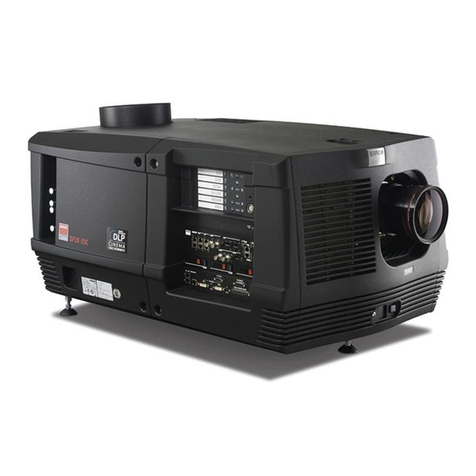
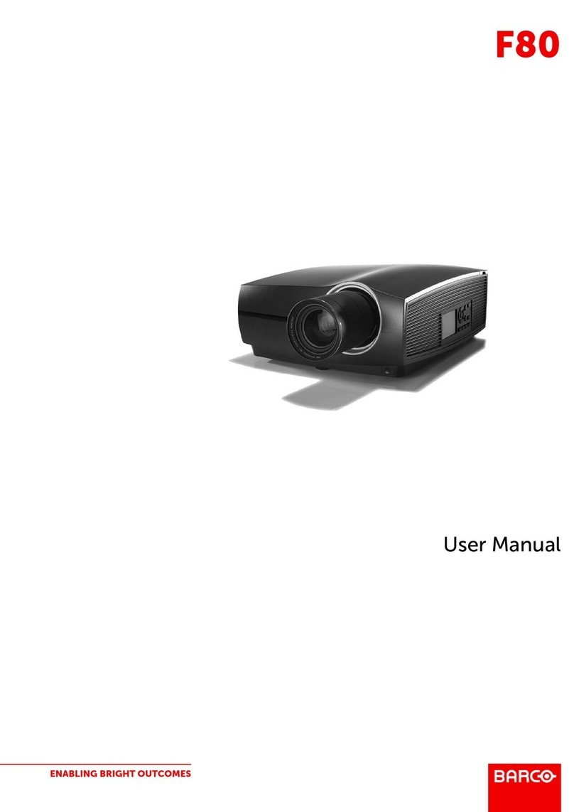
Barco F70 Series User manual

ENABLING BRIGHT OUTCOMES
Service manual
F70

Registered office: Barco NV
President Kennedypark 35, 8500 Kortrijk, Belgium
www.barco.com/en/support
www.barco.com
Barco Fredrikstad AS
Habornveien 53, N-1630 Gamle Fredrikstad, Norway
www.barco.com

1Introduction...........................................................................................................................................................................................................9
1.1 Scope and limitations .....................................................................................................................................................................10
1.2 Copyright ...............................................................................................................................................................................................10
1.3 Trademarks ..........................................................................................................................................................................................10
1.4 Required Handtools.........................................................................................................................................................................10
2General safety .................................................................................................................................................................................................. 11
2.1 General Safety Instructions.........................................................................................................................................................12
2.2 Notice on safety .................................................................................................................................................................................12
2.3 Users Definition..................................................................................................................................................................................12
3Important Safety Instructions................................................................................................................................................................15
3.1 To prevent the risk of electrical shock....................................................................................................................................16
3.2 To prevent personal injury............................................................................................................................................................16
3.3 To prevent fire hazard.....................................................................................................................................................................17
3.4 To prevent projector damage .....................................................................................................................................................17
3.5 On Servicing ........................................................................................................................................................................................18
3.6 To prevent battery explosion (PCB)........................................................................................................................................18
3.7 Precautions during lens shift ......................................................................................................................................................19
3.8 Laser Safety.........................................................................................................................................................................................19
3.9 Warning labels....................................................................................................................................................................................19
4DLP System General Description .......................................................................................................................................................21
4.1 GP7optical principle ........................................................................................................................................................................22
4.2 The DMD Device...............................................................................................................................................................................24
4.3 The Grayscale image .....................................................................................................................................................................24
4.4 Adding Color........................................................................................................................................................................................25
4.5 Single chip DLP projection system .........................................................................................................................................25
5GP7 system functional description...................................................................................................................................................27
5.1 Electronic platform ...........................................................................................................................................................................28
5.2 I/O’s and processing tasks: ......................................................................................................................................................... 28
5.3 Block diagram GP7 Platform ......................................................................................................................................................29
5.4 Wiring Matrix........................................................................................................................................................................................31
5.5 Firmware................................................................................................................................................................................................32
5.6 System Safety Loop ........................................................................................................................................................................33
5.7 Laser driver Principle and error codes ..................................................................................................................................34
6GP7 periodic maintenance ......................................................................................................................................................................37
6.1 Service Interval Matrix....................................................................................................................................................................38
6.2 Service kits available ......................................................................................................................................................................38
723–0018 /02 F70 3
Table of contents

723–0018 /02 F704
7OSD / display menu ......................................................................................................................................................................................41
7.1 Service Menu ......................................................................................................................................................................................42
7.2 Troubleshooting tools .....................................................................................................................................................................43
8Thermal management system...............................................................................................................................................................45
8.1 Ventilation and cooling...................................................................................................................................................................46
8.2 Liquid cooling system .....................................................................................................................................................................47
8.3 Fans..........................................................................................................................................................................................................48
8.3.1 Fan overview .................................................................................................................................................................... 48
8.3.2 Fan Inlet/Outlet................................................................................................................................................................49
8.3.3 FAN Phosphor wheel...................................................................................................................................................49
8.3.4 Fan Optics..........................................................................................................................................................................49
8.3.5 Fan PSU..............................................................................................................................................................................49
8.3.6 Fan PCB Scaler .............................................................................................................................................................. 49
8.3.7 Fan and pump. Numbering and location. .........................................................................................................50
8.4 Thermal Sensors...............................................................................................................................................................................51
8.5 DMD Cooling .......................................................................................................................................................................................51
8.6 System thermal diagram...............................................................................................................................................................52
9Lenses and adjustment .............................................................................................................................................................................55
9.1 Scheimpflug adjustment ...............................................................................................................................................................56
9.2 Locking the lens position..............................................................................................................................................................56
10 Optical adjustments ....................................................................................................................................................................................59
10.1 Perfecting the lighting path..........................................................................................................................................................60
10.2 Lighting Mirror adjustment:..........................................................................................................................................................60
10.3 Lighting mirror: Horizontal (x) Adjustment ..........................................................................................................................60
10.4 Lighting Mirror: Vertical (y) Adjustment.................................................................................................................................61
10.5 Focus: Relay tube lens focus adjustment ...........................................................................................................................61
10.6 Color Uniformity, TI Loop mirrors adjustment ...................................................................................................................62
10.6.1 Color Uniformity, left TI Loop mirror: ...................................................................................................................62
11 Colorwheels.......................................................................................................................................................................................................63
11.1 Replacing the colorwheel assy..................................................................................................................................................64
11.2 Colorwheel index adjustment.....................................................................................................................................................64
11.3 Index adjustment procedure.......................................................................................................................................................64
12 Phosphor wheel..............................................................................................................................................................................................67
12.1 Replace the phosphor wheel assembly ...............................................................................................................................68
12.2 Entering Prospector diagnostic tool........................................................................................................................................68
12.3 Calibrating the phosphor wheel ................................................................................................................................................68
13 Laser pulsing adjustment........................................................................................................................................................................71
13.1 Procedure..............................................................................................................................................................................................72
14 XPS actuator .....................................................................................................................................................................................................75
14.1 XPS actuator replacement...........................................................................................................................................................76
14.2 Calibrating the XPS actuator......................................................................................................................................................76
15 Power Supply Unit (PSU) .........................................................................................................................................................................79
15.1 AC Input .................................................................................................................................................................................................80
15.2 Output specification.........................................................................................................................................................................80
15.3 Connectors ...........................................................................................................................................................................................80
15.4 Mainboard connector J4 ...............................................................................................................................................................81
15.5 Thermal Hub Connector J3:........................................................................................................................................................81
15.6 Laser driver connector J2: ...........................................................................................................................................................82

723–0018 /02 F70 5
15.7 Power supply diagnostics.............................................................................................................................................................82
15.7.1 Power good output........................................................................................................................................................82
15.7.2 AC input voltage monitoring.....................................................................................................................................82
15.7.3 Power supply ID..............................................................................................................................................................82
15.7.4 Temperature monitoring.............................................................................................................................................82
15.7.5 Consumption monitoring............................................................................................................................................82
15.7.6 Weight of PSU .................................................................................................................................................................82
16 Troubleshooting.............................................................................................................................................................................................83
16.1 Status LED indications...................................................................................................................................................................84
16.2 LED’s on Thermal Hub and Mainboard................................................................................................................................84
16.2.1 Thermal Hub Board LED’s. ......................................................................................................................................84
16.2.2 Main Board LED’s..........................................................................................................................................................85
16.3 Available Diagnostic Tools...........................................................................................................................................................86
16.3.1 Prospector..........................................................................................................................................................................86
16.3.2 pd Diagnostic....................................................................................................................................................................87
16.3.3 Log Extractor ....................................................................................................................................................................87
16.3.4 OSD.......................................................................................................................................................................................87
16.3.5 LCD........................................................................................................................................................................................87
16.4 Troubleshooting.................................................................................................................................................................................87
16.4.1 Explanation of the codes ...........................................................................................................................................88
16.4.2 Troubleshooting checklist..........................................................................................................................................89
16.4.3 Log files ...............................................................................................................................................................................98
17 Assembly hierarchy.................................................................................................................................................................................. 103
17.1 Disassembly / Assembly instructions ................................................................................................................................. 105
17.2 Safety Precautions........................................................................................................................................................................ 105
17.3 Removing the projector cover panels................................................................................................................................. 105
17.3.1 Remove top cover ...................................................................................................................................................... 105
17.3.2 Remove the Rear Cover ......................................................................................................................................... 106
17.3.3 Remove the front cover ........................................................................................................................................... 107
17.3.4 Remove the right and left side cover................................................................................................................ 107
17.4 Removing peripheral PCBs...................................................................................................................................................... 108
17.4.1 Removal of display and keypad module ........................................................................................................ 108
17.4.2 PCB GP6/GP7 IR Receiver and LED Board TOP.................................................................................... 109
17.4.3 PCB Front USB & Trigger board ........................................................................................................................ 109
17.4.4 PCB IR Front ................................................................................................................................................................. 109
17.4.5 Switch Air/smoke filter...............................................................................................................................................110
17.4.6 PCB Temp sensor board #1 (Inlet).....................................................................................................................110
17.4.7 PCB temp sensor board #2 (Outlet) ..................................................................................................................112
18 Scheduled operations..............................................................................................................................................................................115
18.1 Scheduled operations matrix....................................................................................................................................................116
18.2 20000 hours LFM service...........................................................................................................................................................116
18.2.1 Phosphor wheel............................................................................................................................................................117
18.2.2 Fan Phosphor wheel ..................................................................................................................................................117
18.2.3 Colorwheel cassette...................................................................................................................................................118
18.2.4 GP7 FE PSU...................................................................................................................................................................118
18.2.5 Fan PSU............................................................................................................................................................................119
18.2.6 Fan PCB Scaler ........................................................................................................................................................... 120
18.2.7 Fan Optics....................................................................................................................................................................... 121
18.2.8 Laser Cluster ................................................................................................................................................................. 122
18.2.9 Remove the Liquid cooling pumps on Laser Cluster. ............................................................................. 123
18.2.10 Remove the laser cluster........................................................................................................................................ 125
18.2.11 Cleaning the cooling pump surface .................................................................................................................. 126

723–0018 /02 F706
18.2.12 XPS Actuator Assy..................................................................................................................................................... 128
18.3 40000 hours service..................................................................................................................................................................... 128
18.3.1 Liquid cooling system, generic handling instructions. ............................................................................ 128
18.3.2 Fan outlet......................................................................................................................................................................... 129
18.3.3 Fan Inlet ........................................................................................................................................................................... 129
18.3.4 Liquid cooling pumps................................................................................................................................................ 130
18.3.5 Liquid cooling pump for DMD. ............................................................................................................................. 131
18.3.6 Cleaning the cooling pump surface .................................................................................................................. 132
19 Technical operations................................................................................................................................................................................ 133
19.1 PCB Main ........................................................................................................................................................................................... 134
19.1.1 PCB removal preparations .................................................................................................................................... 134
19.1.2 PCB Main assembly removal............................................................................................................................... 135
19.2 PCB Laser driver boards ........................................................................................................................................................... 136
19.3 DMD, DMD board and CLGA & DMD heatsink elements ....................................................................................... 137
19.4 GP7 PCB DMD Board................................................................................................................................................................. 138
19.5 CLGA & DMD................................................................................................................................................................................... 138
19.6 Re-assembly after PCB DMD or DMD/CLGA repair.................................................................................................. 139
19.7 GP7 Heatsink DMD Front & Rear Assemblies.............................................................................................................. 140
19.8 GP7 Heatsink DMD Front assembly ................................................................................................................................... 141
19.9 Remove the Laser Interface .................................................................................................................................................... 141
19.10 Install new laser interface.......................................................................................................................................................... 142
19.11 PCB Thermal Hub Board........................................................................................................................................................... 143
19.11.1 PCB Thermal Hub board ........................................................................................................................................ 143
19.11.2 PCB Thermal hub, complete assy removal.................................................................................................. 144
20 TI loop................................................................................................................................................................................................................. 145
20.1 General................................................................................................................................................................................................ 146
20.2 Overview Engine assembly...................................................................................................................................................... 146
20.3 Opening and component identification.............................................................................................................................. 146
20.3.1 Opening the Ti Loop.................................................................................................................................................. 146
20.3.2 Overview inside the TI Loop ................................................................................................................................. 147
20.3.3 Dichroic Filter B/Y....................................................................................................................................................... 147
20.3.4 Barrel PW lens Assy.................................................................................................................................................. 148
20.3.5 Mirrors Blue.................................................................................................................................................................... 148
20.3.6 390 Blue Loop Lens 3............................................................................................................................................... 149
20.3.7 390 Blue Loop Lens 4............................................................................................................................................... 149
20.3.8 Diffusor blue loop ........................................................................................................................................................ 149
20.3.9 390 RGBY Converging Lenses........................................................................................................................... 150
20.3.10 Rod carrier ...................................................................................................................................................................... 152
21 Illumination Engine ................................................................................................................................................................................... 153
21.1 Iris Assembly .................................................................................................................................................................................... 154
21.2 Relay tube assembly.................................................................................................................................................................... 154
21.3 PCB CLO (Constant Light Output)....................................................................................................................................... 155
21.4 Folding mirror assembl ............................................................................................................................................................... 156
22 Lens shift assembly.................................................................................................................................................................................. 157
22.1 Lens shift assembly motors...................................................................................................................................................... 159
22.2 Lens position sensors (Horizontal and Vertical) ........................................................................................................... 159
22.3 PCB lens connectors ................................................................................................................................................................... 160
22.4 Lens shift assembly and optical actuator ......................................................................................................................... 160
22.5 TIR Prism............................................................................................................................................................................................ 162
22.5.1 Remove the TIR prism ............................................................................................................................................. 162
22.5.2 Cleaning the TIR prism............................................................................................................................................ 163

723–0018 /02 F70 7
22.5.3 Reassemble the TIR prism.................................................................................................................................... 163

23 Prism Housing.............................................................................................................................................................................................. 165
23.1 Prism Housing ................................................................................................................................................................................. 166

723–0018 /02 F708

723–0018 /02 F7010
1.1 Scope and limitations
Scope
This document is intended to describe fault resolution, low frequency maintenance and parts replacement
procedures for the Barco F70. Only partners named in service agreement with Barco Fredrikstad AS may
carry out procedures detailed in this document. Information contained herein is subject to change without
further notice; please refer to online documentation for updated information.
1.2 Copyright
Copyright
All rights reserved. No part of this document may be copied, reproduced or translated. It shall not otherwise be
recorded, transmitted or stored in a retrieval system without prior written consent of Barco.
1.3 Trademarks
Trademarks
Brands and product names mentioned in this manual may be trademarks, registered trademarks or copyrights
of their respective holders. All brands and product names mentioned in this manual serve as comments or
examples and are not to be understood as advertising for the product or their manufacturers.
1.4 Required Handtools
Required Handtools
The following tools are needed for servicing the unit:
•Screwdriver,s, Torx6, 8, 10, 20.
•Allen Key, Size 1.5, 2, 3, 5mm
•Scalpel
•Screwdriver, Flat head 4mm
•Ionized pressurized air for cleaning optical components
•Adjustable thermal heater for releasing Cooling system.
•Suitable cleaner for thermal transfer compound, (Brake / clutch cleaner). Isopropanol can be used, but are
not as powerful as brake cleaner.
Unless otherwise indicated in the procedure, screw torque to be applied is 0.3 Nm.
Introduction

723–0018 /02 F7012
2.1 General Safety Instructions
General Safety Instructions.
•The projector is Class 1 laser product that conforms with IEC EN 60825-1:2014. For Northern America, the
projector is class 3R laser product up to throw ratio 2.33. The projector conforms with IEC 60825–1:2007,
and with performance standards for laser products under 21 CFR 1040, except with respect to those
characteristics authorized by Variance Number 2016–V-0144 effective March 6, 2017
•This projector is Risk Group 2 (RG2) according to IEC EN 62471-5. This projector may become Risk
Group 3 (RG3) when an interchangeable lens with throw ratio greater than 3.15 is installed. For Northern
America, installation requirements according to Risk group 3 (RG3) must be followed when
interchangeable lens with throw ratio greater than 2.33 is installed. Refer to the manual for the lens list and
throw ratio before operation. Such combination of projector and lens are intended for professional use only,
and are not intended for consumer use.
•For RG3, no direct exposure to the beam shall be permitted. For RG3, operators shall control access to the
beam within the hazard distance or install the product at a height that will prevent eye exposure within the
hazard distance.
•This projector has a built-in Class 4 laser cluster. Disassembly or modification is very dangerous and
should never be attempted.
•Any operation or adjustment not specifically instructed by the user’s guide creates the risk of hazardous
laser radiation exposure.
•Do not open or disassemble the projector as this may cause damage by the exposure of laser radiation.
•Do not stare into beam when the projector is on. The bright light may result in permanent eye damage.
•Not following the prescribed control, adjustment or operation procedure may cause damage by the
exposure of laser radiation.
•Before operating this equipment please read this manual thoroughly and retain it for future reference.
•Installation and preliminary adjustments should be performed by properly trained and qualified personnel.
•All warnings on the projector and in the documentation manuals should be adhered to.
•All instructions for operating and use of this equipment must be followed precisely.
•All local installation codes should be adhered to.
2.2 Notice on safety
Safety
This equipment is built in accordance with the requirements of the international safety standards IEC60950-1,
as basis for National safety regulation world wide. The safety standard covers information technology
equipment including electrical business equipment intended to operate in “normal”environments (offices and
homes). This safety standard imposes important requirements on the use of safety critical components,
materials and insulation, in order to protect the user or operator against risk of electric shock and energy
hazard and having access to live parts. Safety standards also impose limits to the internal and external
temperature rises, radiation levels, mechanical stability and strength, enclosure construction and protection
against the risk of fire. Simulated single fault condition testing reduce the risk of hazards and contribute to
ensure the safety of the equipment to the user even when the equipment’s normal operation fails..
2.3 Users Definition
Definition
Throughout this manual, the term SERVICE PERSONNEL refers to Barco authorized persons having
appropriate technical training and experience necessary to be knowledgeable of potential hazards to which
they are exposed (including, but not limited to HIGH VOLTAGE ELECTRIC and ELECTRONIC CIRCUITRY
and HIGH BRIGHTNESS PROJECTORS) in performing a task, and of measures to minimize the potential risk
to themselves or other persons. Only Barco authorized SERVICE PERSONNEL, knowledgeable of such risks,
are allowed to perform service functions inside the product enclosure. The term USER and OPERATOR refers
to any person other than SERVICE PERSONNEL. When an interchangeable lens with throw ratio above a
certain level is installed, the F70 / 90 series projector becomes RG3. Refer to the manual for the lens list and
hazard distance before operation. Such combination of projector and lens are intended for professional use
only, and are not intended for consumer use.
General safety

723–0018 /02 F70 13
FOR PROFESSIONALLY USE ONLY, means installation only can be carried out by BARCO AUTHORIZED
PERSONNEL familiar with potential hazards associated with high intensity light beams.
This product operates on mains voltage. Do not open products without first unplugging the power cord.
It is advised against operating the product with housing top off, as there is a risk of injury caused by high
voltage elements, cuts caused by glass fragments in the event of a ruptured lamp or UV radiation burns.
General safety

723–0018 /02 F7016
3.1 To prevent the risk of electrical shock
Electrical Shock
•This product should be operated from a mono phase AC power source.
•This apparatus must be grounded (earthed) via the supplied 3 conductor AC power cable. If none of the
supplied power cables are the correct one, consult your dealer. If you are unable to insert the plug into the
outlet, contact your electrician to replace your obsolete outlet. Do not defeat the purpose of the grounding-
type plug.
•Do not allow anything to rest on the power cord. Do not locate this product where persons will walk on the
cord. To disconnect the cord, pull it out by the plug. Never pull the cord itself.
•Use only the power cord supplied with your device. While appearing to be similar, other power cords have
not been safety tested at the factory and may not be used to power the device. For a replacement power
cord, contact your dealer.
•Do not operate the projector with a damaged cord. Replace the cord. Do not operate the projector if the
projector has been dropped or damaged - until it has been examined and approved for operation by a
qualified service technician.
•Position the cord so that it will not be tripped over, pulled, or contact hot surfaces.
•If an extension cord is necessary, a cord with a current rating at least equal to that of the projector should
be used. A cord rated for less amperage than the projector may overheat.
•Never push objects of any kind into this product through cabinet slots as they may touch dangerous
voltage points or short out parts that could result in a risk of fire or electrical shock.
•Make sure that no objects enter into the vents and opening of the set.
•Do not expose this projector to rain or moisture.
•The projector is designed for indoor use only. Never operate the unit outdoors.
•Do not immerse or expose this projector in water or other liquids.
•Do not spill liquid of any kind on this projector.
•Should any liquid or solid object fall into the cabinet, unplug the set and have it checked by qualified
service personnel before resuming operations.
•Do not disassemble this projector; always take it to an authorized trained service person when service or
repair work is required.
•Do not use an accessory attachment which is not recommended by the manufacturer.
•Lightning - For added protection for this video product during a lightning storm, or when it is left unattended
and unused for long periods of time, unplug it from the wall outlet. This will prevent damage to the device
due to lightning and AC power-line surges.
3.2 To prevent personal injury.
Personal injury
•To prevent injury and physical damage, always read this manual and all labels on the system before
connecting to the wall outlet or adjusting the projector.
•To prevent injury, take note of the weight of the projector.
•To prevent injury, ensure that the lens and all covers are correctly installed. See installation procedures.
•Warning: high intensity light beam. NEVER look into the lens! High luminance could result in damage to the
eye.
•Warning: extremely high brightness laser: This projector uses extremely high brightness laser. Never
attempt to look directly into the lens or at the laser.
•Always switch off the projector and disconnect from the mains power supply before attempting to remove
any of the projector covers or access parts inside the projector.
•Do not place this equipment on an unstable cart, stand, or table. The product may fall, causing serious
damage to it and possible injury to the user.
•It is hazardous to operate without lens or lens cap. Lenses, shields or ultra violet screens shall be changed
if they have become visibly damaged, for example with cracks or deep scratches, to such an extent that
their effectiveness is impaired.
•Exposure to UV radiation: Some medications are known to make individuals extra sensitive to UV
radiation. The American Conference of Governmental Industrial Hygienists (ACGIH) recommends
occupational UV exposure for an 8 hour day to be less than 0.1 micro-watts per square centimeters of
Important Safety Instructions

723–0018 /02 F70 17
effective UV radiation. An evaluation of the workplace is advised to assure employees are not exposed to
cumulative radiation levels exceeding these government guidelines.
3.3 To prevent fire hazard
Fire Hazard
•Barco projection products are designed and manufactured to meet the most stringent safety regulations.
This projector radiates heat on its external surfaces and from ventilation ducts during normal operation,
which is both normal and safe. Exposing flammable or combustible materials into close proximity of this
projector could result in the spontaneous ignition of that material, resulting in a fire. For this reason, it is
absolutely necessary to leave an “exclusion zone”around all external surfaces of the projector whereby no
flammable or combustible materials are present. The exclusion zone in the exhaust area must be not less
than 100 cm (40”). The exclusion zone on the intake area must not be less than 50 cm (20”). The exclusion
zone on the lens side within the light beam must be at least 1,5 m.
•Do not place flammable or combustible materials near the projector!
•Slots and openings in this equipment are provided for ventilation. To ensure reliable operation of the
projector and to protect it from overheating, these openings must not be blocked or covered.
•.The openings should never be blocked by placing the projector too close to walls, or other similar surface.
Allow for sufficient distance to walls and ceilings to avoid overheating. Minimum safety distance to the
exhaust area of the unit must not be less than 100 cm (40”) and to the intake area, not less than 50 cm
(20”).
•This projector should never be placed near or over a radiator or heat register.
•This projector should not be placed in a built-in installation or enclosure unless proper ventilation is
provided.
•Do not cover the projector or the lens with any material while the projector is in operation. Keep flammable
and combustible materials away from the projector at all times.
•Mount the projector in a well-ventilated area away from sources of ignition and out of direct sun light.
•Never expose the projector to rain or moisture. In the event of fire, use sand, CO2 or dry powder fire
extinguishers.
•Never use water on an electrical fire.
•Always have service performed on this projector by authorized Barco service personnel. Always insist on
genuine Barco re- placement parts. Never use non-Barco replacement parts as they may degrade the
safety of this projector.
•Projection rooms must be well ventilated or cooled in order to avoid heat buildup.
•Let the projector cool down completely before storing. Remove cord from the projector when storing.
3.4 To prevent projector damage
Preventing Projector Damage.
•To ensure correct airflow is maintained, and that the projector complies with Electromagnetic Compatibility
(EMC) requirements, it should only be operated when all of its covers in place.
•Always remove lens cap before switching on the projector. If the lens cap is not removed, it may melt due
to the high energy light emitted through the lens. Melting the lens cap will permanently damage the surface
of the projection lens.
•The projector must always be installed in a manner, which ensures free flow of air into its air inlets and
unimpeded evacuation of the hot air from its cooling system.
•Slots and openings in the cabinet are provided for ventilation. To ensure reliable operation of the product
and to protect it from overheating, these openings must not be blocked or covered. The openings should
never be blocked by placing the product on a bed, sofa, rug, or other similar surface. This product should
never be placed near or over a radiator or heat register. The device should not be placed in a built-in
installation or enclosure unless proper ventilation is provided. Ensure that nothing can be spilled on, or
dropped inside the projector. If this does happen, switch off and unplug the mains supply immediately. Do
not operate the projector again until it has been checked by BARCO authorized service personnel..
•Do not block the projector cooling fans or free air movement around the projector. Minimum safety distance
to the exhaust area of the unit must not be less than 100 cm (40”) and to the intake area, not less than 50
cm (20”)
•Do not use this equipment near water.
Important Safety Instructions

723–0018 /02 F7018
•Special care for Laser Beams: Special care should be used when DLP projectors are used in the same
room as high power laser equipment. Direct or indirect hitting of a laser beam on to the lens can severely
damage the Digital Mirror Devices™in which case there is a loss of warranty.
•Never place the projector in direct sun light. Sun light on the lens can severely damage the Digital Mirror
Devices™in which case there is a loss of warranty.
•Save the original shipping carton and packing material. They will come in handy if you ever have to ship
your equipment. For maximum protection, repack your set as it was originally packed at the factory.
•Unplug this product from the wall outlet before cleaning. Do not use liquid cleaners or aerosol cleaners.
Use a damp cloth for cleaning. Never use strong solvents, such as thinner or benzine, or abrasive
cleaners, since these will damage the cabinet. Stubborn stains may be removed with a cloth lightly
dampened with mild detergent solution.
•To ensure the highest optical performance and resolution, the projection lenses are specially treated with
an anti-reflective coating, therefore, avoid touching the lens. To remove dust on the lens, use a soft dry
cloth. Do not use a damp cloth, detergent
3.5 On Servicing
Servicing
•Do not attempt to service this product yourself, as opening or removing covers may expose you to
dangerous voltage potentials and risk of electric shock.
•Refer all servicing to BARCO authorized repair centers.
•Attempts to alter the factory-set internal controls or to change other control settings not specially discussed
in this manual can lead to permanent damage to the projector and cancellation of the warranty.
•Unplug this product from the wall outlet and refer servicing to BARCO authorized service technicians under
the following conditions:
•When the power cord or plug is damaged or frayed.
•If liquid has been spilled into the equipment.
•If the product has been exposed to rain or water.
•If the product does not operate normally when the operating instructions are followed. Adjust only those
controls that are covered by the operating instructions since improper adjustment of the other controls may
result in damage and will often require extensive work by a qualified technician to restore the product to
normal operation.
•If the product has been dropped or the cabinet has been damaged.
•If the product exhibits a distinct change in performance, indicating a need for service.
•Replacement parts: When replacement parts are required, be sure the service technician has used original
Barco replacement parts. Unauthorized substitutions may result in degraded performance and reliability,
fire, electric shock or other hazards. Unauthorized substitutions may void warranty.
•Safety check: Upon completion of any service or repairs to this projector, ask the service technician to
perform safety checks to determine that the product is in proper operating condition.
•Possible explosion hazard: Always keep in mind the caution below:
3.6 To prevent battery explosion (PCB)
This applies to the battery on the PCB
CAUTION:
Risk of explosion if battery is replaced by an incorrect type.
Dispose of used batteries according to the instructions, or instruction to replace the complete PCB.
Important Safety Instructions

723–0018 /02 F70 19
3.7 Precautions during lens shift
Lens shift
For Lens shift procedure, see User Guide.
WARNING: When changing lens, always close the shutter to avoid accidentally staring in to the
lens opening. This light can be harmful to the eyes.
Close the shutter by pressing the shutter button on the keypad panel. The key will illuminate red
when the shutter is closed.
3.8 Laser Safety
WARNING: Class 1 laser RG2 Product. This projector may become RG3. Refer User Manual
before operating.
Do not stare into beam. This projector has a Class 4 laser cluster. Do not attempt to disassemble or
modify this projector.
Special precautions have to be taken in order to protect persons and environment. Laser radiation
is defined as harmful to persons and objects, and must be handled according to instructions given.
All power must be switched off during service and replacement of optical components.
After reassembly of Cluster, Laser interface and TI Loop, the unit must be properly tested against
leak of light due to improper reassembly of the parts.
This test must take place in a closed area / room, with only service personnel present. The area /
room must have safety signs and warnings indicating that there is a restricted / danger area, with
access only to certified personnel. Protective googles has to be used by persons inside the test
area.
3.9 Warning labels
Warning Labels
Warning labels are positioned inside the projector, where extra Safety precautions are necessary.
Image 3-1
Important Safety Instructions
Other manuals for F70 Series
4
Table of contents
Other Barco Projector manuals

Barco
Barco SP4K-C Series User guide

Barco
Barco RLS W12 User manual

Barco
Barco BarcoData 1209S User manual

Barco
Barco UDM W22 User manual

Barco
Barco RLM G5 Performer User manual

Barco
Barco RLM W8 User manual

Barco
Barco R9000972 User manual

Barco
Barco ELM G10 User manual

Barco
Barco DP2K-23B User manual

Barco
Barco F90 - W13WUXGA User manual

Barco
Barco OV-D2 User manual

Barco
Barco BarcoReality SIM6 Ultra R9040150 User manual

Barco
Barco 70/60 User manual

Barco
Barco Loki User manual

Barco
Barco G100 User manual

Barco
Barco DP2K-15C User manual

Barco
Barco Galaxy NH-12 User manual

Barco
Barco DP-1500 User manual

Barco
Barco R9002380 User manual

Barco
Barco Galaxy NW12 Installation instructions