- 3 -
Table of Contents
To be continued on next page
Table of Contents -------------------------------------------------------------------------- 3
Chapter 1 : Preparation ------------------------------------------------------------------ 5
Contents of The Kit------------------------------------------------------------------------ 6
Purpose of This Kit ------------------------------------------------------------------------------------------------------------------ 6
Content of the Kit -------------------------------------------------------------------------------------------------------------------- 6
Preparation----------------------------------------------------------------------------------- 7
How to Remove the Top Cover --------------------------------------------------------------------------------------------------- 7
No Cover Support ! ------------------------------------------------------------------------------------------------------------------ 7
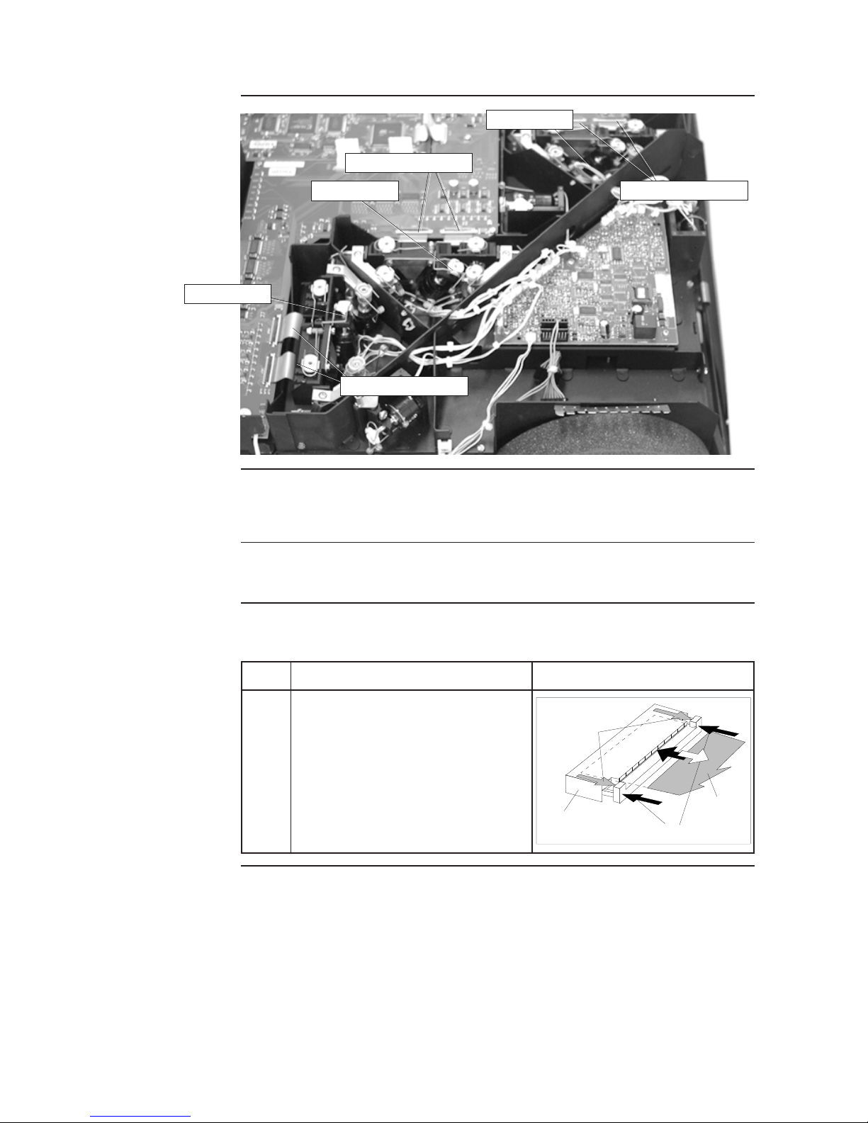
Location of the LCD Panels ------------------------------------------------------------------------------------------------------- 8
Attention ! ------------------------------------------------------------------------------------------------------------------------------ 8
Antistatic Protection Steps --------------------------------------------------------------------------------------------------------- 8
Electrical Disconnection of the Panels ------------------------------------------------------------------------------------------8
Electrical Dis-connection of the Servo Motors ---------------------------------- 9
When Necessary -------------------------------------------------------------------------------------------------------------------- 9
How to disconnect the Cables of the Servo Motors. ------------------------------------------------------------------------ 9
Chapter 2 : Replacement of the LCD Panel ------------------------------------- 10
Removing the LCD Unit out of the Projector ------------------------------------11
Necessary Tools ------------------------------------------------------------------------------------------------------------------- 11
How to Remove the LCD Panel holder --------------------------------------------------------------------------------------- 11
Disassembling the LCD Holder ----------------------------------------------------- 13
Necessary Tool --------------------------------------------------------------------------------------------------------------------- 13
Attention ! ---------------------------------------------------------------------------------------------------------------------------- 13
Antistatic Protection Steps ------------------------------------------------------------------------------------------------------- 13
How to Remove the LCD Panel ------------------------------------------------------------------------------------------------ 13
Assembling the LCD Holder---------------------------------------------------------- 16
Necessary Tool --------------------------------------------------------------------------------------------------------------------- 16
Attention ! ---------------------------------------------------------------------------------------------------------------------------- 16
Antistatic Protection Steps ------------------------------------------------------------------------------------------------------- 16
How to fix the LCD Panel --------------------------------------------------------------------------------------------------------16
Installation of the MOCA LCD Holder --------------------------------------------- 19
Necessary Tools ------------------------------------------------------------------------------------------------------------------- 19
How to Install the LCD Unit ------------------------------------------------------------------------------------------------------ 19