barfield TT1200A Operator's manual

Copyright © 2022 Barfield Inc. All Rights Reserved
USER INSTRUCTION MANUAL
M/N: TT1200A, P/N: 101-00930
M/N: OH58D, P/N: 101-00930-OH58D
Doc P/N: 56-101-00930
Revision H
June 3, 2022
______________________________________
TT1200A & OH58D
Turbine Temperature Test Set

56-101-00930 Revision H Page ii
Corporate Headquarters
4101 Northwest 29thStreet
Miami, Florida 33142
www.barfieldinc.com
Email: [email protected]
Barfield Inc. Confidential and Proprietary Information.
This document and all the information contained herein is the sole property of Barfield Inc.
No intellectual property rights are granted by the delivery of this document or the disclosure of its content.
This entire document is proprietary information and shall not be reproduced or disclosed to a third party without
the express written consent of Barfield Inc.
This document and its content shall not be used for any purpose other than that for which it is supplied.

56-101-00930 Revision H Page iii
CONTACT INFORMATION
Users are requested to notify the manufacturer of any discrepancy, omission, or error found in this
manual. Inquiries should include specific questions and reference the publication title, number, chapter,
page, figure, paragraph, and effective date.
Please send comments to:
TECHNICAL CUSTOMER SUPPORT - GSTE
BARFIELD, INC.
P.O. BOX 025367
MIAMI, FL 33102-5367
USA
Telephone (305) 894-5400
(800) 321-1039
Fax (305) 894-5401
Email gsesales@barfieldinc.com

56-101-00930 Revision H Page iv
MAINTENANCE AND REPAIR INFORMATION
The manufacturer of this equipment does not recommend the user to attempt any maintenance or repair.
In case of malfunction, contact the manufacturer to obtain the list of approved repair facilities worldwide,
ensuring that this equipment will be serviced using proper procedures and certified instruments.
BARFIELD PRODUCT SUPPORT DIVISION
Telephone (305) 894-5400
(800) 321-1039
Fax (305) 894-5401
Email gsesales@barfieldinc.com
Shipping Address:
Barfield, Inc.
4101 NW 29th Street
Miami, Florida 33142
USA
Mailing Address:
Barfield, Inc.
P.O. Box 025367
Miami, FL 33102-5367
USA
Vector Aerospace
Shipping Address:
Telephone 33 (0)1 30 18 53 48
Fax 33 (0)1 30 18 53 45
Vector Aerospace
1 Boulevard du 19 Mars 1962 –BP50064
F95503 GONESSE Cedex,
France

56-101-00930 Revision H Page v
REVISION RECORD
REV.
ECO #
REV. DATE
DESCRIPTION OF CHANGE
A
N/A
February 28, 2003
Initial Release.
B
260-00722
May 9, 2008
Specifications, Company Contact
Information, and Logo were Updated.
Chapters and Sections were reorganized.
C
260-00807
November 16, 2010
Update style; add the note that this also
relates to M/N OH58D.
D
260-00829
April 12, 2011
Updated warranty information
E
260-00914
May 21, 2012
Updated recertification to include 101-
00930-OH58D.
F
260-00914
September 25, 2014
Updated Barfield logo & warranty info.
G
260-01254
April 20, 2020
Removal of CE label on Figure 1. Figure 2
updated. Revision of General Description,
item 10. Document reformatted. Minor
grammar revisions.
H
260-01375
June 3, 2022
Addition of note below item 13 on p. 6 and
section C. to p. ix. Updated formatting and
reordered items.

56-101-00930 Revision H Page vi
TABLE OF CONTENTS
Contact Information
Maintenance and Repair Information
Revision Record
Table of Contents
List of Figures
List of Tables
PAGE
INTRODUCTION.................................................................................................................... viii
1. PUBLICATION BREAKDOWN..................................................................................................viii
2. INFORMATION PROVIDED WITH THE TEST SET..................................................................viii
3. RECERTIFICATION....................................................................................................................ix
CHAPTER 1: GENERAL........................................................................................................... 1
1. INTENDED USE .........................................................................................................................1
2. DESCRIPTION............................................................................................................................ 1
3. SPECIFICATIONS...................................................................................................................... 3
4. CAPABILITIES............................................................................................................................ 4
CHAPTER 2: OPERATION....................................................................................................... 5
1. OPERATING CONTROLS ..........................................................................................................5
2. GENERAL OPERATING INSTRUCTIONS..................................................................................7
3. POWER UP (INITIALIZATION)................................................................................................... 8
4. MENU DISPLAYS.......................................................................................................................9
CHAPTER 3: TEST PROCEDURES....................................................................................... 11
1. MOVING COIL TYPE INDICATOR TEST PROCEDURES........................................................ 11
2. POTENTIOMETRIC OR SERVO-TYPE INDICATOR TEST PROCEDURE..................................
(Without Lead Resistance) ..................................................................................................... 14
CHAPTER 4: RECEIVING, SHIPPING & STORAGE............................................................. 16
1. RECEIVING.............................................................................................................................. 16
2. SHIPPING................................................................................................................................. 16
3. STORAGE ................................................................................................................................ 16

56-101-00930 Revision H Page vii
LIST OF FIGURES
PAGE
Figure 1 Identification Label...............................................................................................................viii
Figure 2 Owner Warranty Registration Card ........................................................................................ix
Figure 3 Limited One Year Warranty.................................................................................................... x
Figure 4 TT1200A Test Set..................................................................................................................1
Figure 5 TT1200A Front Panel & Switches .......................................................................................... 5
Figure 6 Power Up Message Display Sequence ..................................................................................9
Figure 7 Display Menu Flowchart......................................................................................................... 9
LIST OF TABLES
PAGE
Table 1 Physical Characteristics........................................................................................................... 3
Table 2 Temperature Measurement .....................................................................................................3
Table 3 Lead Resistance Measurement ...............................................................................................3
Table 4 Insulation Measurement ..........................................................................................................3
Table 5 Simulated System Resistance Measurement........................................................................... 3

56-101-00930 Revision H Page viii
INTRODUCTION
1. PUBLICATION BREAKDOWN
A. This user instruction manual establishes the standards of operation for the TT1200A Turbine
Temperature Test Set.
Its purpose is to provide sufficient information for the personnel unfamiliar with this Tester to
understand this equipment, identify its parts, and operate it in accordance with proper
procedures, operating techniques, precautions, and limitations.
Note: The manufacturer has designed this equipment to be safe when operated using the
procedures and instructions detailed in this manual. Do not use this equipment for any
other purpose than that stated, as the protection provided by the equipment may be
impaired.
2. INFORMATION PROVIDED WITH THE TEST SET
In addition to this User Instruction Manual, the Test Set is delivered with the items described below.
A. The identification label located on the front bulkhead of the Test Set (Figure 1), provides the
following information:
Manufacturer Name
Designation of Equipment
Equipment Part Number
Equipment Model Number Equipment Serial Number
Equipment Modification (if applicable) Equipment Options (if applicable)
Figure 1 Identification Label
TURBINE TEMPERATURE TEST SET
101-00930
TT1200A

56-101-00930 Revision H Page ix
B. Each new or re-certified unit is delivered with a Certificate (not pictured) that shows the date
when the unit was tested by the manufacturer, its serial number and when the next certification
is due. This certificate confirms that the unit performed according to its design specifications.
C. The Owner’s Warranty Registration card (refer to Figure 2) is to be completed by the owner and
returned to Barfield, Inc. within ten (10) days of purchase to ensure automatic update of printed
matter and validation of warranty.
To register your unit, please visit https://www.barfieldinc.com/warranty_registration or scan the
QR code on the supplied Warranty Registration.
Figure 2 Owner Warranty Registration Card
D. The TT1200A Limited One Year Warranty can be seen in Figure 3.
3. RECERTIFICATION
A. The Test Set P/N 101-00930 and 101-00930-OH58D has a one-year recertification requirement.
Maintenance required by this unit must be performed by qualified technicians in a shop
equipped with the necessary tooling and facilities.

56-101-00930 Revision H Page x
Figure 3 Limited One Year Warranty

56-101-00930 Revision H Page 1
CHAPTER 1: GENERAL
1. INTENDED USE
A. This publication contains the description and the operating procedures for:
1. TT1200A, Digital Turbine Temperature Test Set, P/N 101-00930
2. OH58D, Digital Turbine Temperature Test Set, P/N 101-00930-OH58D
The TT1200A is specifically designed to test and calibrate Chromel - Alumel (CH - AL)
temperature indicating systems.
2. DESCRIPTION
Note: It is recommended that the user read this manual through its entirety to become familiar with
the TT1200A Test Set and use the placard instructions as a quick reference only.
Additionally, it is advisable that the user reviews the specific aircraft system before performing
any tests or checks (refer to the Aircraft Maintenance Manual (AMM)).
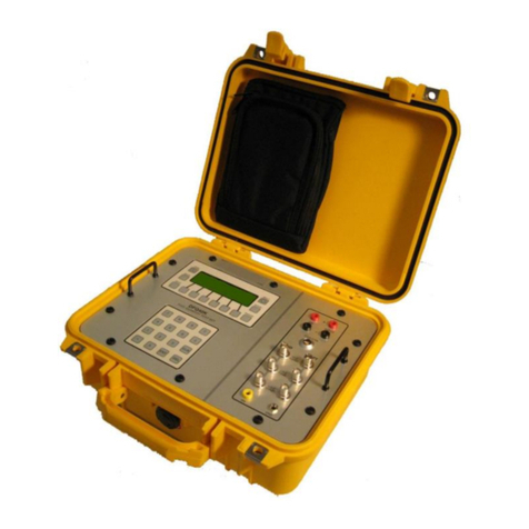
A. The TT1200A (refer to Figure 4) provides the means for quickly troubleshooting aircraft
temperature indicating systems. It has sufficient sensitivity and accuracy to test thermocouple
and system resistance, insulation, and indicator calibration. It features portability, simplicity of
operation, direct reading, and multifunctional versatility.
Figure 4 TT1200A Test Set

56-101-00930 Revision H Page 2
B. The main features of the T1200A are:
1. Microprocessor Based
2. Backlit 16-character alphanumeric LCD, which provides readings with applicable units and
instructional user prompts.
3. Specifically designed to meet all requirements for testing aircraft Chromel - Alumel (CH - AL)
temperature measuring systems, providing an accurate display of thermocouple outputs in
degrees Celsius (°C), Fahrenheit (°F) and Millivolt (mV).
4. Thermocouple and lead resistance measurements to 0.001 Ω and insulation measurements
up to 200 MΩ.
5. Simulates thermocouple outputs and system lead resistances from 2 to 25 Ω.
6. Completely self-contained, self-monitoring, easily portable temperature and resistance
measuring and simulating device for all CH - AL systems with the capability to bench test
indicators.
7. Human engineered for maximum ease of operation.
8. Automatic ambient test point temperature correction.
9. Carrying Case features:
a) Fabricated from high impact plastic
b) Provides a pouch for test lead storage.
c) The lid contains a placard of short operating instructions for the experienced technician.
10. Auto Detection of Cable: At power up, the TT1200A looks to see if the Standard Cable leads
are connected to the panel’s TEST receptacle and displays the prompt “TEST CABLE?” if
no cable is detected. If the Standard Cable leads are then connected to the TEST
receptacle, the prompt “Standard Cable” will be briefly displayed. If the TT1200A is powered
up with the Standard Cable leads already connected to the panel’s TEST receptacle, no
prompt is displayed.
11. Color Coded Function Keypad: For ease of use, the TT1200A keypad is color-coded to
indicate the function, setting, range, and/or mode (soft key) pairing.
12. Auto Off: To save battery power, this “automatic off” feature allows the user to set a turn off
time period for the unit in 5-minute increments (up to 1 hour). (If auto off is disabled, the Test
Set stays on until the batteries become low.)

56-101-00930 Revision H Page 3
3. SPECIFICATIONS
A. Physical Characteristics
Size (H, W, L)
7.0 in. (17.8 cm), 11.0 in. (27.9 cm), 10.0 in. (25.4 cm)
Weight
7.3 lbs. (3.3 kg)
Table 1 Physical Characteristics
B. Temperature
Type
K (CH –AL Thermocouple)
Range
-25°C to +1200°C (certified)
-50°C to +1372°C (extended)
Accuracy
Typical measurement error at 77°F (25°C) ambient: less
than ±0.5°C
Ambient Operating Range
14°F to 122°F (-10°C to +50°C)
Table 2 Temperature Measurement
C. Lead Resistance
Range
0-19.999 Ω in 0.001 Ω increments
0-199.99 Ω in 0.01 Ω increments
0-1.9999 kΩ in 0.0001 kΩ increments
0-19.999 kΩ in 0.001 kΩ increments
Accuracy
±0.05% of reading ±2 counts
Table 3 Lead Resistance Measurement
D. Insulation
Range
0-199.9 kΩ in 0.1 kΩ increments
0-1.999 MΩ in 0.001 MΩ increments
0-19.99 MΩ in 0.01 MΩ increments
0-200 MΩ in 5 MΩ increments
Accuracy
±5% of reading ± 5 counts (200 kΩ, 2 MΩ, and 20 MΩ (ranges)
± 10% of reading ± 5 counts (200 MΩ range)
Excitation
45 VDC nominal
Table 4 Insulation Measurement
E. Simulated System Resistance
Adjusted Range
Less than 2.00 Ω to greater than 25.00 Ω
Fixed Setting
Less than 0.01 Ω
Table 5 Simulated System Resistance Measurement

56-101-00930 Revision H Page 4
4. CAPABILITIES
A. Measures and displays resistance of thermocouples, thermocouple rings and system lead
circuits.
B. Measures and displays insulation resistance of system wiring and other components.
C. Simulates CH - AL thermocouples with or without simulated system lead resistance.
D. Measures and displays values of CH - AL thermocouples in terms of millivolts, millivolts with
ambient compensation, 1°F or 0.1°F, and 1°C or 0.1°C.
E. Automatically compensates for ambient temperature at test lead connection junction point or
indicates this cold junction temperature.

56-101-00930 Revision H Page 5
CHAPTER 2: OPERATION
1. OPERATING CONTROLS
A. The functions of the front panel switches and components are as follows (refer to Figure 5):
Figure 5 TT1200A Front Panel & Switches
1. The PWR (power) pushbutton, when pressed, applies power to the TT1200A and begins the
initialization process.
2. The BKLT (backlight) pushbutton, when pressed, provides a backlight to the LCD to
improve readability under dim lighting conditions. A second press of the key turns the
backlight off. (The backlight goes out automatically five minutes after activation to conserve
batteries, unless the “BKLT auto-off” feature is disabled by pressing the BKLT pushbutton
for 2 or more seconds.)
3. The TEMP ADJ control knob allows coarse adjustment of the temperature. When the
FUNCTION is in the IND Test position, the display shows millivolt readings.
4. The FINE control provides exact adjustment of the temperature or millivolt readings shown
on the display when the FUNCTION switch is in the IND TEST position.
5. The FUNCTION switch is a four-position rotary switch that allows selection of the four main
test functions:
a) RES MEAS (Resistance Measure)
b) INS MEAS (Insulation Measure)
c) IND TEST (Indicator Test)
1
12
13
14
15
16
17
10
9
8
7
6
5
11
2
3
4

56-101-00930 Revision H Page 6
d) TEMP MEAS (Temperature Measure)
6. The RANGE switch is a four-position rotary switch that allows selection of the resistance
and insulation ranges, 20 Ω, 200 Ω, 2 KΩ and 20 KΩ (for Resistance Measuring, RES
MEAS), or 200 KΩ, 2 MΩ, 20 MΩ and 200 MΩ (for Insulation Measuring, INS MEAS.) The
fourth position is also used for 0 Ω system resistance for the IND TEST function.
7. The PTM (Press To Measure) button, when pressed, activates the TT1200A excitation and
measuring processes (when the FUNCTION switch is set to the RES MEAS or INS MEAS
position).
Note: While the TT1200A is processing the measurements, a flashing “M”appears
on the right side of the display. When the process completes, a steady “H” replaces
the “M” on the display.
8. The PTS (Press To Set) button, when pressed, activates the SYS RES switch for system
resistance adjustment. When PTS is held pressed in while rotating the SYS RES, the user
may adjust resistance to the desired resistance setting.
9. The SYS RES (System Resistance) control knob is used to adjust system lead resistance
from 2 to 25 Ω.
10. The TEST connector provides the means for connecting the TT1200A's standard leads or
specifically designed interface cabling.
11. The Display is a 16-character alphanumeric LCD that shows the user prompts and all
readings with associated units.
12. The MENU pushbutton, when pressed, causes the display to show the remaining available
battery life (Battery ###%). In addition, the user may then use the soft keys mV ( ↑ ) or
°F ( ↓ ) to scroll through display messages and option menus.*
13. The CONT pushbutton when held in and used with the soft keys mV (↑) or °F (↓), allows the
user to adjust the display contrast level from 0 to 100. The pushbutton is also a soft key
(ESC) to cancel a function and return the unit to normal operation.*
Note: Units identified with Mod D use a different P/N LCD Display to replace the original P/N
(now obsolete) and will no longer retain adjusted contrast levels but instead will revert
to the factory default at each power up.
14. The mV (millivolt) pushbutton is a toggle which, when pressed, allows the user to select
between two millivolt modes: mV and mV amb. When used with the MENU display, it is a
soft key ( ↑ ) to scroll through MENU selections. When used with the CONT pushbutton, the
user may increase the display contrast.*
Note: The mV mode simulates a DVM function equivalent to having a DVM connected in
parallel at the Test Set’s red and black clips. The mV amb mode configures the
TT1200A for ambient temperature compensation performed at the point of
termination. The displayed millivolt is based on a reference junction at 0°C.
15. The °F(Fahrenheit) pushbutton is a toggle which allows selection between resolutions of
1°F and 0.1°F. The Display alternates between the resolutions with each button press.
When used with the MENU key, the soft key ( ↓ ) may be used to scroll to MENU selections.
When used with the CONT pushbutton, the user may decrease the display contrast. *
16. The °C (Celsius) pushbutton is a toggle that allows selection between resolutions 1°C and
0.1°C. The Display alternates between resolutions with each button press. The pushbutton
is also a soft key (ENT) to enter Menu confirmations.*

56-101-00930 Revision H Page 7
*Note: The soft keys referred to in item numbers 12-16 of Figure 4 may also be used as
numeric keys when entering a password.
17. Two battery holders contain six (6) C-cell alkaline batteries that provide the power for all test
set functions.
18. Standard Leads P/N 175-00215 for Test Set P/N 101-00930 or P/N 175-00217 for Test Set
P/N 101-00930-OH58D.
2. GENERAL OPERATING INSTRUCTIONS
Consult the temperature indicator system and/or engine manufacturer's instructions for procedures
and specifications.
Note: It is recommended that the complete TT1200A Operation procedures be read
before attempting to use the Test Set.
A. Protective Circuits
Although the TT1200A has input protection, do not connect the test set to an energized circuit.
B. Battery Installation and Verification
1. Remove the covers from the battery holders located on the right side of the case. Lift the left
side of the TT1200A so that the batteries slide out. Insert three (3) alkaline C-cell batteries
into each holder with all positive terminals facing outward. Reattach the covers to each tube.
2. At power-up the display shows the message “Battery ###%”, to indicate the remaining
available battery life.
3. The user may check battery condition at any time by pressing the MENU pushbutton.
4. When the available battery power goes below 15%, the Test Set displays the “Battery Low”
message approximately every minute. When the available battery power goes below 7%,
the T/S displays the “Battery Low” message every 30 seconds. In this case, replace the
batteries as was described above.
C. Precautions
1. Do NOT press the PTM or PTS pushbuttons with test clips connected to the aircraft
indicator. The applied current may damage the indicator.
2. Do NOT connect test clips to an energized circuit. Although the TT1200A is provided with
protective devices, not all damaging potentials may be completely safe.
3. Allow sufficient time for test clips to stabilize to the temperature of the terminals to which
they are connected for temperature tests.
4. For greatest accuracy, measure system and thermocouple resistance with a cold engine.
5. To conserve battery power, power down the Test Set when it is not in use.
6. The Test Set displays the message “Battery Low” indicating that the batteries should be
replaced.

56-101-00930 Revision H Page 8
D. Hot Engine Testing
A hot engine causes thermocouples to generate a small potential which produces errors in
measured resistance values. This effect is natural for any type of resistance measuring
instrument.
The effect, however, can be avoided by taking two measurements:
1. With test leads connected in one polarity;
2. Reversing the lead connections for the second measurement.
Add the two readings and divide by two. (The true value is equal to the average of the two
readings.) The two readings must be taken in quick succession so that the thermocouple
temperature will be the same for both readings. If the thermocouples are too hot, the readings
will be too far from nominal to provide sufficient accuracy. In this case, wait for the engine to
further cool.
E. Setting the System Resistance
1. Short the test lead clips together.
2. Set the FUNCTION switch to RES MEAS.
3. Set the RANGE switch to 200 Ω.
4. While pressing in the PTS pushbutton in, rotate the SYS RES knob to set the required
system resistance for the specific aircraft-under-test (refer to the specific AMM).
Note: While the PTS button is held in, the TT1200A shows the message “PTS”
on the right of the display.
5. Release the PTS button.
Note: The TT1200A replaces the message “PTS” with “SET” on the display.
3. POWER UP (INITIALIZATION)
A. At power up, the TT1200A displays a series of informational messages (refer to Figure 5),
including the unit’s software version (Ver ##.##.##.X); the available battery power percentage
(Battery ###%) and the calibration due date (Cal. Due, mm/yyyy).
Note: If the calibration due date is less than 30 days before the calibration is needed, the
message “Cal. In ## Days” displays. If the calibration due date has been exceeded,
the unit displays “Cal Required”.
B. If no errors are detected during power up, the instrument enters normal mode. If the function
switch is in the RES MEAS or INS MEAS position, the message “Push PTM” displays.

56-101-00930 Revision H Page 9
Figure 6 Power Up Message Display Sequence
4. MENU DISPLAYS
A. Once the MENU button is pressed, the user may use the mV ( ↑ ) or the °F ( ↓ ) soft keys to
scroll through the message display and option menus as shown (refer to Figure 7):
Figure 7 Display Menu Flowchart
1. Battery ###%
The display shows the available battery power percentage available.
2. Ver. ##.##.##.X
The display shows the current software version installed in the unit.

56-101-00930 Revision H Page 10
3. Cal Due mm/yyyy
The display shows the month and year when calibration is due.
4. Auto Off
This feature allows the user to set a time period for the unit to automatically turn off when
not in use. To activate the feature at the Auto ± display, press ENT (°C). Use the mV or °F
keys to set 5-minute increments (up to 60 minutes). Press ENT to accept entry. Press ESC
to exit from Menu options.
5. Maintenance
This menu option is password protected and allows other maintenance functions such as
setting the calibration due date.
This manual suits for next models
3
Table of contents
Other barfield Test Equipment manuals
barfield
barfield 2311FA Operator's manual
barfield
barfield TT-1000A Operator's manual
barfield
barfield TT-1000A Operator's manual
barfield
barfield DPS400 User manual
barfield
barfield 1811D Series Operator's manual

barfield
barfield DPS1000 Operator's manual
barfield
barfield DPS1000 Operator's manual

barfield
barfield DPS1000 Operator's manual
barfield
barfield 2548H Operator's manual

barfield
barfield 2548H Owner's manual
