barfield DPS400 User manual

INSTRUCTION MANUAL
DPS400
PITOT-STATIC TEST SET
P/N 101-01180
MOD P
56-101-01180-C November 5, 2003


INSTRUCTION MANUAL
DPS400
56-101-01180-C TITLE
Page 1
November 5, 2003
USERS ARE KINDLY REQUESTED TO NOTIFY THE MANUFACTURER OF ANY
DISCREPANCY, OMISSION ORERROR FOUND IN THIS MANUAL.
INQUIRIES SHOULD INCLUDE SPECIFIC QUESTIONS AND ALWAYS
REFERENCE THE PUBLICATION TITLE, NUMBER, CHAPTER, PAGE, FIGURE,
PARAGRAPH, AND EFFECTIVE DATE.
PLEASE SEND COMMENTS TO:
TECHNICAL CUSTOMER SUPPORT - GSTE
BARFIELD CORPORATION
P.O. BOX 025367
MIAMI, FL 33142
USA
TELEPHONE: (305) 871-3900
(800) 321-1039
FAX: (305) 876-1680


INSTRUCTION MANUAL
DPS400
56-101-01180-C ATTENTION
Page 1
November 5, 2003
ATTENTION
Although every effort has been made to provide the end user of this equipment with the
most current and accurate information, it may be necessary to revise this manual in the
future. Please be sure to complete and return a Revision Request Form to Barfield GSTE
Revision Services.
Additionally, Barfield MUST have your name and address on file as a registered user of
this equipment to ensure validation of the warranty. Please complete the OWNER
WARRANTY REGISTRATION card promptly and return it. This card insures validation of
the warranty.


INSTRUCTION MANUAL
DPS400
56-101-01180-C REVISION RECORD
Page 1
November 5, 2003
REVISION RECORD
REV.
ECO #
REV. DATE
DESCRIPTION OF CHANGE
A
B
C
N/A
260-00462
260-00643
and
260-00642
October 29, 1996
May 15, 2001
November 2, 2003
Initial Release
Revised to show software/menu/screen changes
as per ECO.
Revised to newest format and per EC’s for latest
software modification (MOD P) and new keyboard
assembly (Option C)


INSTRUCTION MANUAL
DPS400
56-101-01180-C LOARF
Page 1
November 5, 2003
LIST OF APPROVED REPAIR FACILITIES
TRADE-NAME
BARFIELD PRODUCT SUPPORT DIVISION
Shipping Address:
Telephone (305) 871-3900 Barfield Inc.
(800) 321-1039 4101 N.W. 29th Street
Fax (305) 876-1680 Miami, Florida 33142
USA
Mailing Address:
BarfieldInc.
P.O. Box 025367
Miami, FL 33142
USA


INSTRUCTION MANUAL
DPS400
56-101-01180-C CONTENTS
Page 1
November 5, 2003
TABLE OF CONTENTS
Title Page
Attention Pages
Revision Record Page
List of Approved Repair Facilities
Table of Contents
List of Illustrations
Introduction
GENERAL INFORMATION AND OPERATING INSTRUCTIONS Chapter-Section
Description ..................................................................................................................1-1
Specifications and Capabilities.....................................................................................1-2
Theory of Operation.....................................................................................................1-3
Operation.....................................................................................................................1-4
Shipping.......................................................................................................................1-5
Storage........................................................................................................................1-6

INSTRUCTION MANUAL
DPS400
56-101-01180-C CONTENTS
Page 2
November 3, 2003
TABLE OF CONTENTS (Continued)
CHAPTER 1
GENERAL INFORMATION AND OPERATING INSTRUCTIONS
PAGE
INTRODUCTION.............................................................................. INTRO/ 1
1. PUBLICATION BREAKDOWN .................................................................. 1
2. IDENTIFICATION – MODIFICATION STATUS ........................................ 1
3. RECERTIFICATION .............................................................................. 2
SECTION 1: DESCRIPTION .....................................................................................1-1/ 1
1. PURPOSE OF MANUAL ......................................................................... 1
2. GENERAL DESCRIPTION ......................................................................... 1
3. PHYSICAL DESCRIPTION ........................................................................ 2
A. Carrying Case ...................................................................................... 2
B. Switches and controls ............................................................................ 3
B. Hose Assembly ................................................................................... 5
C. Power Cables ................................................................................... 5
SECTION 2: SPECIFICATIONS AND CAPABILITIES ...........................................1-2/ 1
1 PHYSICAL DATA ...........................................................................................1
2. SPECIFICATIONS ...........................................................................................1
3. ACCURACY ...........................................................................................1
4. OPERATING TEMPERATURE RANGE ...................................................... 2
5. DISPLAY UNITS ...........................................................................................2
6. PRESSURE MEDIA ...........................................................................................2
7. TRANSDUCERS ...........................................................................................2
8. INPUT POWER ...........................................................................................2
SECTION 3: THEORY OF OPERATION .................................................................1-3 / 1
1. PRESSURE/VACUUM REQUIREMENTS .................................................... 1
2. REGULATOR/CONTROL VALVE OPERATION ........................................... 1
3. POWER SUPPLY CIRCUITS........................................................................ 1
4. PROTECTION CIRCUITS ........................................................................... 1
5. PNEUMATIC SCHEMATIC DIAGRAM ...................................................... 2

INSTRUCTION MANUAL
DPS400
56-101-01180-C CONTENTS
Page 3
November 3, 2003
TABLE OF CONTENTS (Continued)
PAGE
SECTION 4: OPERATION .......................................................................................1-4/ 1
1. GENERAL ..................................................................................................1
2. CONTROL PANEL INSTRUCTIONS.............................................................2
A. PRELIMINARY SETUP ........................................................................3
B. SETTING THE DISPLAY UNITS ........................................................5
C. SETTING THE PROTECTION LIMITS................................................10
D. PROTECTION CIRCUIT RESET INSTRUCTIONS.............................21
(1) Altitude Limits Exceedance.........................................................21
(2) VSI Rate Limit Exceedance........................................................21
(3) Airspeed/Mach Limit Exceedance...............................................22
F. DISPLAYING FIRMWARE VERSION .................................................22
3. LEAK CHECKING THE TESTER ..............................................................23
A. PRELIMINARY SETUP ...................................................................23
B. STATIC LEAK CHECKS ...................................................................24
C. PITOT LEAK CHECKS ...................................................................26
D. APPLYING LEAK CORRECTION .....................................................28
4. AIRCRAFT TEST ......................................................................................29
A. PRELIMINARY SETUP.......................................................................29
B. PITOT SYSTEM TEST........................................................................30
(1) Leak Test .....................................................................................30
(2) Airspeed Checks............................................................................30
C. STATIC SYSTEM TEST .........................................................................31
D. COMBINED PITOT/STATIC TEST.........................................................34
(1) Combined Altitude/Airspeed Tests.................................................34
E. MACHMETER TESTS ............................................................................37
F. ENGINE PRESSURE RATIO (EPR).......................................................38
(1) Preliminary ..................................................................................38
(2) Test ..................................................................................38
G. MANIFOLD PRESSURE GAUGE...........................................................39
(1) Preliminary ..................................................................................39
(2) Test ..................................................................................39
5. SHUTDOWN PROCEDURES .........................................................................41
A. STANDARD TEST SET SHUTDOWN PROCEDURES.........................41

INSTRUCTION MANUAL
DPS400
56-101-01180-C CONTENTS
Page 4
November 3, 2003
TABLE OF CONTENTS (Continued)
PAGE
SECTION 5: SHIPPING ......................................................................................1-5/ 1
1. RECEIVING .................................................................................................. 1
2. SHIPPING .................................................................................................. 1
SECTION 6: STORAGE.................................................................................................. 1-6/ 1
1. PROCEDURE ............................................................................................... 1

INSTRUCTION MANUAL
DPS400
56-101-01180-C LOFT
Page 1
November 5, 2003
LIST OF FIGURES AND TABLES
SECTION FIGURE / TABLE TITLE PAGE
INTRO 1 Identification Label................................................ 1
INTRO 2 Owner Warranty Registration Card ...................... 2
INTRO 3 Limited Warranty Registration Card...................... 2
1-1 4 DPS400 (Mod P) Pitot-Static Tester...................... 1
1-1 5 Tester Switches and Controls............................... 3
1-3 6 Pneumatic Diagram .............................................. 2
1-4 7 Display Units Flowchart......................................... 6
1-4 8 Enable/Disable Flowchart.................................... 10
1-4 9 Static Port Limits Flowchart ................................ 12
1-4 10 Pitot Port Limits Flowchart .................................. 15
1-4 11 Firmware Flowchart............................................. 23
1-4 1 Machmeter Test Table........................................ 37
1-4 2 EPR Test Table .................................................. 38
1-4 3 Manifold Pressure Test Table............................. 40


INSTRUCTION MANUAL
DPS400
56-101-01180-C INTRO
Page 1
November 5, 2003
INTRODUCTION
1. PUBLICATION BREAKDOWN
This instruction manual establishes the standards of operation for the Barfield Digital Pitot
Static Test Set and has been prepared using ATA Specification 101 as a guide.
Questions related to this manual should be submitted in writing to:
Barfield
P.O. Box 025367
Miami, FL 33102-5367
USA
Attn: Technical Customer Support - GSTE
Inquiries should be specific and refer to the publication title, number, chapter, page, figure,
paragraph, and effective date.
Changes, when approved, will be published as revisions to the basic publication
2. IDENTIFICATION - MODIFICATION STATUS
A. The identification label, (Figure 1), located on the front bulkhead of the Test Set, provides
the following information:
Manufacturers' Name Equipment Modification
Designation of Equipment Equipment Options
Equipment Part Number Equipment Model Number
Equipment Description Equipment Serial Number
IDENTIFICATION LABEL
Figure 1
B. In addition to the identification label, there are three (3) other record forms packaged with
the test set as follows:
INSTRUCTION MANUAL
DPS400
56-101-01180-C INTRO
Page 2
November 5, 2003
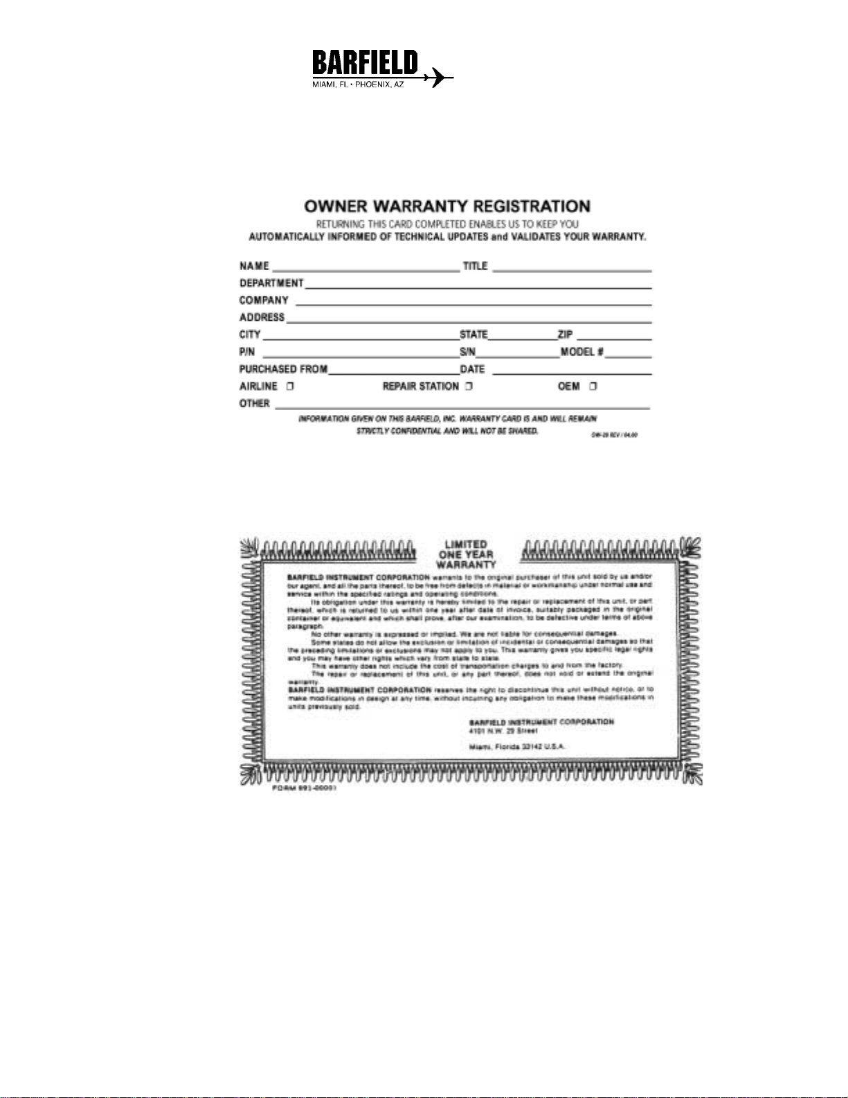
(1) The Owner's Warranty Registration card, (Figure 2), which is to be completed by
the owner and returned to the Barfield within ten (10) days of purchase to insure
automatic update of printed matter and validation of warranty.
OWNER WARRANTY REGISTRATION CARD
Figure 2
(2) The Limited Warranty Statement Card, (Figure 3), which lists the manufacturer's
obligation to the original purchaser.
LIMITED WARRANTY STATEMENT CARD
Figure 3
(3) The Certificate of Calibration
Each new unit and re-certified unit is delivered with a Certificate of Calibration
that shows the date of the last calibration and when the next calibration is due.
It certifies the accuracy of the unit and lists the part number and serial number
to which it applies.

INSTRUCTION MANUAL
DPS400
56-101-01180-C INTRO
Page 3
November 5, 2003
3. RECERTIFICATION
The Test Set P/N 101-01180 has a one-year recertification requirement. Qualified technicians
in a shop equipped with the necessary tooling and facilities must perform the maintenance
required by this unit.

This manual suits for next models
1
Table of contents
Other barfield Test Equipment manuals

barfield
barfield 1811NG Operator's manual

barfield
barfield 1811D Series Operator's manual

barfield
barfield DPS1000 Operator's manual

barfield
barfield 2548H Owner's manual

barfield
barfield DPS1000 Operator's manual

barfield
barfield 1811GA Series Operator's manual

barfield
barfield DPS1000 Operator's manual

barfield
barfield 1811G Operator's manual

barfield
barfield DFQ40K Operator's manual

barfield
barfield TT-1000A Operator's manual


