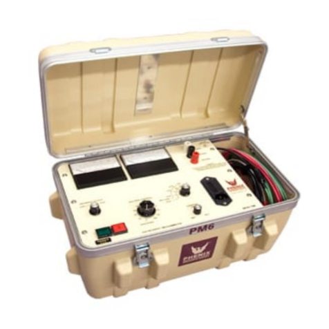
Presys MCS-12-IS User manual

®
MCS-12-IS
Universal
Process
Calibrator
TECHNICAL MANUAL
presys

EM0414-01 (09/20/2021) - Translated version of the document EM0370-01
IMPORTANT INSTRUCTIONS:
• This manual contains instructions for the MCS-12-IS (in the rest of the manual called by calibrator)
designed for use in hazardous areas. Read the entire manual before using the calibrator.
• Before using the calibrator, carefully read the section “Special conditions for safe use”.
• Keep the calibrator in a dry environment whenever possible.
• In case of failure or suspected failure, especially in safe operation, send the instrument for repair to the
factory., always send the instrument to the factory for repair.
• When not in daily use, before starting up, let the calibrator be turned on for at least one hour.
The warranty conditions are available on our website:
www.presys.com.br/warranty
presys

1
Table Of Contents
Marking details........................................................................................................................................................ 3
Special conditions for safe use ............................................................................................................................. 4
1 - Introduction ........................................................................................................................................................ 5
1.1. General Description ...................................................................................................................................... 5
1.2. Specifications – Inputs .................................................................................................................................. 6
1.3. Specifications – Outputs ................................................................................................................................ 9
2 - Operation......................................................................................................................................................... 14
2.1. Parts Identification ...................................................................................................................................... 14
2.2. Battery and charger .................................................................................................................................... 17
2.3. Using Calibrator: Basic Functions ................................................................................................................ 17
2.4. Measurement or input functions ................................................................................................................... 20
2.5. Generation or Output Functions ................................................................................................................... 28
2.6. Available power supplies ............................................................................................................................. 32
2.7. Calibration examples................................................................................................................................... 33
2.8. Special Programming .................................................................................................................................. 35
2.8.1. FILTER Programming ........................................................................................................................... 35
2.8.2. DECIMAL Programming ........................................................................................................................ 35
2.8.3. Probe ................................................................................................................................................... 36
2.8.4. STEP Programming .............................................................................................................................. 37
2.8.5. RAMP Programming ............................................................................................................................. 38
2.9. Special Functions ....................................................................................................................................... 39
2.9.1. SCALE Function ................................................................................................................................... 40
2.9.2. CAL Function........................................................................................................................................ 41
2.9.3. SCALE Function ................................................................................................................................... 44
2.9.4. CONV Function .................................................................................................................................... 46
presys

2
2.10. MEM Command ........................................................................................................................................ 47
2.11. Warning Messages ................................................................................................................................... 48
3 - Adjustment ...................................................................................................................................................... 49
3.1. Input adjustment (IN)................................................................................................................................... 50
3.2. Output adjustment (OUT) ............................................................................................................................ 52
Notes.................................................................................................................................................................... 56
presys

3
MCS-12-IS
Marking details
Note: The Ex Compliance Certificate is sent with the instrument and its accessories.
presys

4
Special conditions for safe use
• Use the calibrator only as described in this technical manual.
• The battery should only be charged in a safe area, using the charger provided. To avoid explosion or fire, use only
the battery (BT12-IS) and charger (CG12-IS) specified by Presys.
• Never replace the battery in a hazardous area.
• Do not use the serial communication port in an explosive atmosphere.
• The calibrator's aluminum metallic enclosure is protected by a leather case (BC12-IS) that should always house it
when in a hazardous area.
• The intrinsic safety of the instrument is only valid for the connections shown in this manual, respecting the
intrinsically safe input and output parameters. The entity parameters and connections are illustrated in items 2.4, 2.5
and 2.6 - Operation.
• To avoid damage to the instrument and invalidate the Ex certification, never apply a voltage greater than 30 V
between the terminals and the metallic enclosure of the instrument.
• Never open the calibrator. Opening the enclosure may void the calibrator Ex certification.
• Do not use tools on the calibrator that may cause sparks; this practice can cause an explosion.
• Never perform maintenance on the calibrator; the components used are specified and cannot be changed.
• Never use the calibrator in an area close to explosive dust.
presys

5
1 - Introduction
1.1. General Description
MCS-12-IS is a universal process calibrator designed to be used in hazardous areas where explosive or
flammable vapors are present. Enables the measurement and generation of signals used in Instrumentation and
Process Control. It is designed to provide the necessary resources in order to facilitate the work of keeping the
instruments of the process adjusted and calibrated. It has high levels of accuracy, including aspects related to
changes in ambient temperature and the maintenance of specifications over long periods of time. Its construction
takes into account the field use, thus including items of great value such as: bag with straps to fasten on the belt or
on the shoulder allowing freedom for the hands, liquid crystal display with high contrast facilitating visibility in low light
environments, rechargeable battery and large memory capacity to store the values obtained, making it possible to
transfer them to the microcomputer, when necessary. In addition to these, several construction factors that add
quality and efficiency to MCS-12-IS can be mentioned.
It incorporates the most modern concepts of union of adjustments and calibrations with information
technology, where data are shared both by the instrument and by the computer, giving efficiency to the treatment of
information, in the form of issuing reports and certificates, the automated management of tasks and the organization
and archiving of data, that is, it covers an entire context aimed at complying with quality procedures, mainly related to
the ISO-9000 standard.
presys

6
1.2. Specifications – Inputs
Input Ranges
Resolution
Accuracy
Remarks
millivolt
-150 to 150 mV
0.001 mV
0.01 % FS*
Rinput > 10 M
150 to 2050 mV
0.01 mV
0.02 % FS
auto-ranging
volt
-0.5 to 11 V
11 to 30 V
0.0001 V
0.0001 V
0.02 % FS
0.02 % FS
Rinput > 1 M
mA
-5 to 24.5 mA
0.0001 mA
0.02 % FS
Rinput < 100
Resistance
0 to 400
400 to 2050
0.01
0.01
0.02 % FS
0.03 % FS
Excitation current
0.31 mA, auto-ranging
frequency **
0 to 600 Hz
0.01 Hz
0.02 Hz
Rinput > 50 k
600 to 1300 Hz
0.1 Hz
0.2 Hz
Voltage DC max = 30 V
1300 to 10000 Hz
1 Hz
2 Hz
AC Signal from 1.5 to 30 V
counter**
0 to 108 - 1 count
1 count
________
The same remark as frequency
Pulses Frequency < 9000 Hz
(*) FS = Full Scale
(**) Accuracy valid since the output frequency is not configured.
presys

7
Input Ranges
Resolution
Accuracy
Remarks
Pt-100
-200 to 850 C / -328 to 1562 F
0.01 C / 0.01 °F
0.2 C / 0.4 F
IEC-60751
Pt-1000
-200 to 280 C / -328 to 1562 F
0.1 C / 0.1 °F
0.2 C / 0.4 F
IEC-60751
Cu-10
-200 to 260 C / -328 to 500 F
0.1 C / 0.1 °F
4.0 C / 8.0 F
Minco 16-9
Ni-100
-60 to 250 C / -76 to 482 F
0.1 C / 0.1 °F
0.4 C / 0.8 F
DIN-43760
probe*
-200 to 850 C / -328 to 1562 F
0.01 C / 0.01 °F
0.1 C / 0.2 F
IEC 60751
TC-J
-210 to 1200 C / -346 to 2192 F
0.1 C / 0.1 °F
0.2 C / 0.4 F
IEC-60584
TC-K
-270 to -150 C / -454 to -238 F
0.1 C / 0.1 °F
0.5 C / 1.0 F
IEC-60584
-150 to 1370 C / -238 to 2498 F
0.1 C / 0.1 °F
0.2 C / 0.4 F
TC-T
-260 to -200 C / -436 to -328 F
0.1 C / 0.1 °F
0.6 C / 1.2 F
IEC-60584
-200 to -75 C / -328 to -103 F
0.1 C / 0.1 °F
0.4 C / 0.8 F
-75 to 400 C / -103 to 752 F
0.1 C / 0.1 °F
0.2 C / 0.4 F
(*) Probe is an independent input for a reference RTD in order to use as standard thermometer. The accuracy is
related only to calibrator input.
presys

8
Input Ranges
Resolution
Accuracy
Remarks
TC-B
50 to 250 C / 122 to 482 F
0.1 C / 0.1 F
2.5 C / 5.0 F
IEC-60584
250 to 500 C / 482 to 932 F
0.1 C / 0.1 F
1.5 C / 3.0 F
500 to 1200 C / 932 to 2192 F
0.1 C / 0.1 F
1.0 C / 2.0 F
1200 to 1820 C / 2192 to 3308 F
0.1 C / 0.1 F
0.7 C / 1.4 F
TC-R
-50 to 300 C / -58 to 572 F
0.1 C / 0.1 F
1.0 C / 2.0 F
IEC-60584
300 to 1760 C / 572 to 3200 F
0.1 C / 0.1 F
0.7 C / 1.4 F
TC-S
-50 to 300 C / -58 to 572 F
0.1 C / 0.1 F
1.0 C / 2.0 F
IEC-60584
300 to 1760 C / 572 to 3200 F
0.1 C / 0.1 F
0.7 C / 1.4 F
TC-E
-270 to -150 C / -454 to -238 F
0.1 C / 0.1 F
0.3 C / 0.6 F
IEC-60584
-150 to 1000 C / -238 to 1832 F
0.1 C / 0.1 F
0.1 C / 0.2 F
TC-N
-260 to -200 C / -436 to -328 F
0.1 C / 0.1 F
1.0 C / 2.0 F
IEC-60584
-200 to -20 C / -328 to -4 F
0.1 C / 0.1 F
0.4 C / 0.8 F
-20 to 1300 C / -4 to 2372 F
0.1 C / 0.1 F
0.2 C / 0.4 F
TC-L
-200 to 900 C / -328 to 1652 F
0.1 C / 0.1 F
0.2 C / 0.4 F
DIN-43710
TC-C
0 to 1500 C / 32 to 2732 F
0.1 C / 0.1 F
0.5 C / 1.0 F
W5Re / W26Re
1500 to 2320 C / 2732 to 4208 F
0.1 C / 0.1 F
0.7 C / 1.4 F
W5Re / W26Re
presys

9
1.3. Specifications – Outputs
Output Ranges
Resolution
Accuracy
Remarks
millivolt
-10 to 110 mV
0.001 mV
0.02 % FS
Rout < 0.3
volt
0 to 12 V
0.0001 V
0.02 % FS
Rout < 0.3
mA
0 to 22 mA
0.0001 mA
0.02 % FS
Rmax = 450
Resistance
0 to 400
400 to 2500
0.01
0.1
0.02 % FS
0.03 % FS
For external excitation
current of 1.0 mA
frequency
0 to 100 Hz
0 to 10000 Hz
0.01 Hz
1 Hz
0.02 Hz
2 Hz
Peak value: 12 V / 25 mA
max.
pulse
0 to 108 - 1 pulse
1 pulse
________
Peak value: 22 V / 25 mA max.
Pulses frequency up to 10000 Hz
Pt-100
-200 to 850 C / -328 to 1562 F
0.01 C / 0.01 F
0.2 C / 0.4 F
IEC-60751
Pt-1000
-200 to 400 C / -328 to 752 F
0.1 C / 0.1 F
0.1 C / 0.2 F
IEC-60751
Cu-10
-200 to 260 C / -328 to 500 F
0.1 C / 0.1 F
2.0 C / 4.0 F
Minco 16-9
Ni-100
-60 to 250 C / -76 to 482 F
0.1 C / 0.1 F
0.2 C / 0.4 F
DIN-43760
presys

10
Output Ranges
Resolution
Accuracy
Remarks
TC-J
-210 to 1200 C / -346 to 2192 F
0.1 C / 0.1 F
0.4 C / 0.8 F
IEC-60584
TC-K
-270 to -150 C / -454 to -238 F
0.1 C / 0.1 F
1.0 C/ 2.0 F
IEC-60584
-150 to 1370 C / -238 to 2498 F
0.1 C / 0.1 F
0.4 C / 0.8 F
TC-T
-260 to -200 C / -436 to -328 F
0.1 C / 0.1 F
1.2 C / 2.4 F
IEC-60584
-200 to -75 C / -328 to -103 F
0.1 C / 0.1 F
0.8 C / 1.6 F
-75 to 400 C / -103 to 752 F
0.1 C / 0.1 F
0.4 C / 0.8 F
TC-B
50 to 250 C / 122 to 482 F
0.1 C / 0.1 F
5.0 C / 10.0 F
IEC-60584
250 to 500 C / 482 to 932 F
0.1 C / 0.1 F
3.0 C / 6.0 F
500 to 1200 C / 932 to 2192 F
0.1 C / 0.1 F
2.0 C / 4.0 F
1200 to 1820 C / 2192 to 3308 F
0.1 C / 0.1 F
1.4 C / 2.8 F
presys

11
Output Ranges
Resolution
Accuracy
Remarks
TC-R
-50 to 300 C / -58 to 572 F
0.1 C / 0.1 F
2.0 C / 4.0 F
IEC-60584
300 to 1760 C / 572 to 3200 F
0.1 C / 0.1 F
1.4 C / 2.8 F
TC-S
-50 to 300 C / -58 to 572 F
0.1 C / 0.1 F
2.0 C / 4.0 F
IEC-60584
300 to 1760 C / 572 to 3200 F
0.1 C / 0.1 F
1.4 C/ 2.8 F
TC-E
-270 to -150 C / -454 to -238 F
0.1 C / 0.1 F
0.6 C / 1.2 F
IEC-60584
-150 to 1000 C / -238 to 1832 F
0.1 C / 0.1 F
0.2 C / 0.4 F
TC-N
-260 to -200 C / -436 to -328 F
0.1 C / 0.1 F
2.0 C / 4.0 F
IEC-60584
-200 to -20 C / -328 to -4 F
0.1 C / 0.1 F
0.8 C / 1.6 F
-20 to 1300 C / -4 to 2372 F
0.1 C / 0.1 F
0.4 C / 0.8 F
TC-L
-200 to 900 C / -328 to 1652 F
0.1 C / 0.1 F
0.4 C / 0.8 F
DIN-43710
TC-C
0 to 1500 C / 32 to 2732 F
0.1 C / 0.1 F
0.5 C / 1.0 F
W5Re / W26Re
1500 to 2320 C / 2732 to 4208 F
0.1 C / 0.1 F
0.7 C / 1.4 F
W5Re / W26Re
Accuracy values are valid within a year and temperature range of 20 to 26 °C. Outside these limits add
0.001 % FS / C taking 23 °C as the reference temperature. For thermocouples, using the internal cold junction
compensation add a cold junction compensation error of 0.2 C or 0.4 F max.
presys

12
Probe
Independent input for RTD (Probe). Probe is a high accuracy 4-wire Pt100 available under previous consult.
For a higher level of accuracy, it is possible to configure the parameters of the sensor Callendar-Van Dusen
curve in the MCS-12-IS, correcting the errors found in the sensor certificate (see section 3.8.3 - Probe).
Software Special Functions
- Any output programmable in:
1) STEP: 10%, 20%, 25% or up to 11 programmable setpoints via key or adjustable time.
2) RAMP: up and down with programmable travel and dwell time.
- Special functions:
1) SCALE: makes the scaling of both input and output in 6 digits and allows the configuration of decimal point.
2) CAL: scales the input in same unit of output.
3) CONV: converts any input into any output, galvanically isolated.
- MEM command: It can store up to eight types of configuration chosen by user.
presys

13
Measures 2, 3 and 4-wire RTDs.
Transmitter Power Supply: 12 Vcc / 22 mA. 15V (open) / 30 mA (short circuit) – nominal.
50 Vdc In/Out isolation.
Five-minute warm-up time.
Operating temperature range: 0 to 50 C.
Relative humidity: 90% RH non-condensing.
Rechargeable batteries, up to 8 hours of operation, depending on the functions used.
RS-232/485 Serial Communication.
Includes instruction manual, carrying case, test leads and battery charger.
Optional Certificate of Calibration.
Dimensions: 137 mm x 225 mm x 70 mm (height, width and depth).
Weight: 2.0 kg approx.
Enclosure Protection Degree: IP20.
1 year warranty, except for rechargeable battery.
Notes:
Changes can be introduced in the instrument, altering specifications in this manual.
presys

14
2 - Operation
2.1. Parts Identification
Front panel
Fig. 01 - Front Panel
presys

15
Left side-view panel Right side-view panel
Fig. 02 - Side Panels
presys

16
Ways to use the transport bag
Fig. 03 - Ways to use the transport bag
Accessories: The bag has two compartments; one is used to house the calibrator and the other is used to keep
several accessories such as probes, adaptor to connect thermocouple wires, spare fuse, straps for transport and use
in the field, and also the technical manual.
presys

17
2.2. Battery and charger
The calibrator is supplied with rechargeable batteries which enable up to 8 hours of continuous use. This
autonomy is reduced when the current output or the 12 Vdc power supply for transmitters. A charger is also provided,
which can be connected to 110 or 220 Vac. Care should be taken when changing the 110-220 Vac selection switch in
the charger; time required for a full charge is 14 hours. When the display indicates LOW BAT, it is necessary to
recharge the instrument, which will continue in operation for a few minutes. The battery should only be charged in
a safe area. Only the charger (CG12-IS) and battery (BT12-IS) specified by Presys must be used, otherwise
there is a risk of fire or explosion.
The batteries used by the calibrator are made of Nickel - Metal Hydride (Ni - MH). This new technology
for rechargeable batteries does not have the undesirable characteristics of memory effect and environmental
pollution as their preceding batteries made of Nickel Cadmium (Ni-Cd).
2.3. Using Calibrator: Basic Functions
When powered on, the calibrator goes through a self-test routine and shows the last adjustment date and
the value of the battery voltage. In case of failure, it displays a message to indicate RAM error or E2PROM error; if
that occurs, the instrument should be sent for repair. The battery voltage is constantly monitored and the low battery
warning is provided.
presys

18
After the self-test is completed, the display shows the starting menu:
IN OUT EXEC
CONF ADJ COM
IN / OUT - Selects the input/output functions
ADJ - Selects functions which adjust the calibrator itself (see chapter Adjustment).
Do not enter in ADJ option before reading the warning in section 4 - Adjustment.
COM - Refers to the communication with the computer, described in an appropriate manual.
EXEC - Used to activate an input or output option which has been previously selected.
CONF - Takes to the sub-menu:
CF PRG MEM DATE
FN BAT LCD P
CF changes both the input and output temperature units from °C to °F and vice-versa. It also enables to
choose the temperature scale between IPTS-68 and ITS-90. It follows the encoding scheme described below:
C-90 ITS-90 temperature scale in Celsius degrees.
F-68 IPTS-68 temperature scale in Fahrenheit degrees.
presys
Table of contents
Other Presys Test Equipment manuals
Presys
Presys T-25N User manual
Presys
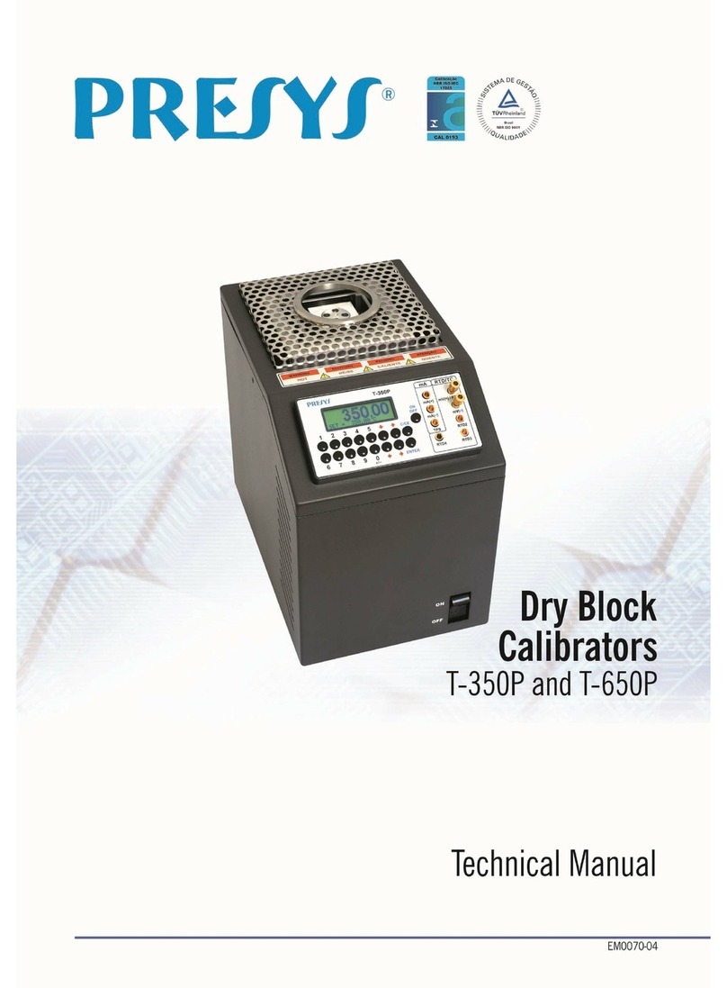
Presys T-350P User manual

Presys
Presys PCON-Y18-LP User manual
Presys
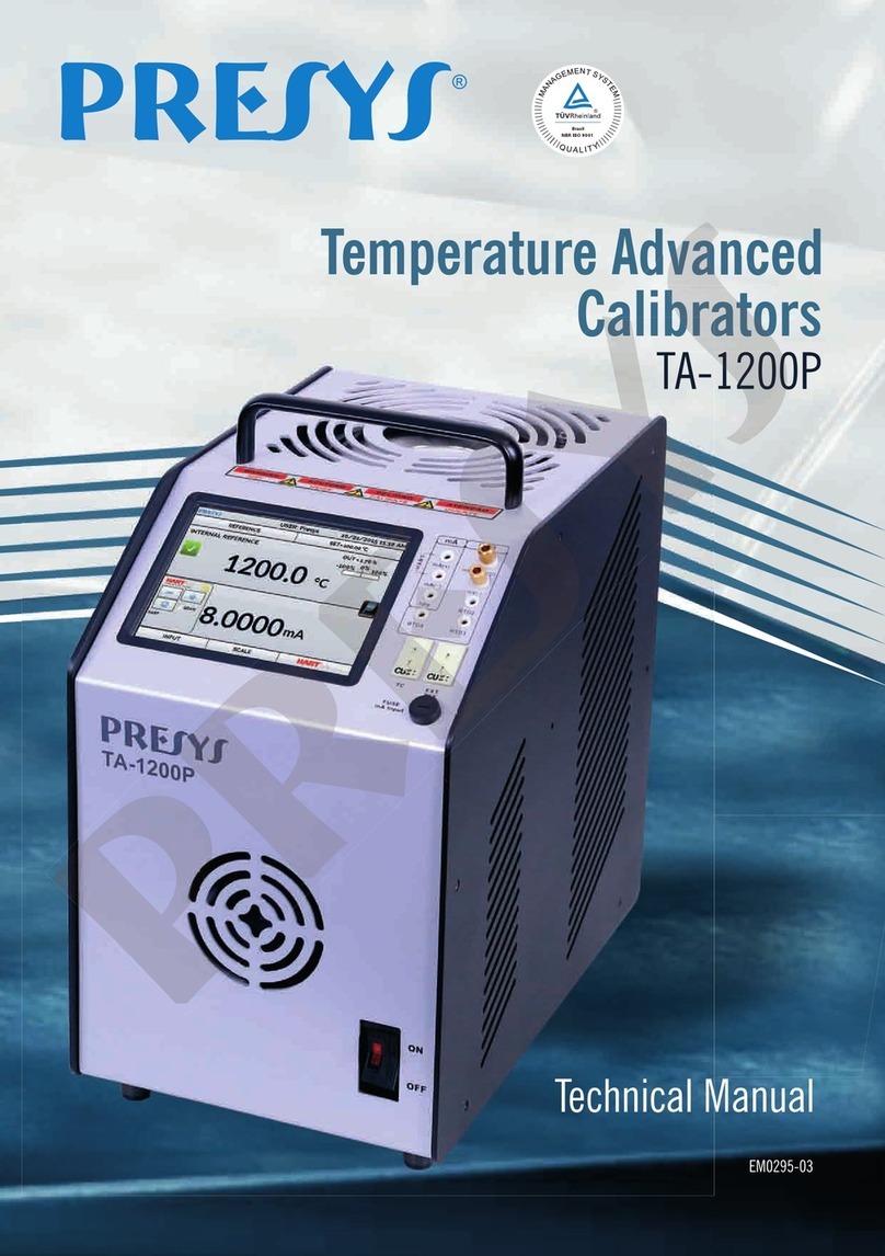
Presys TA-1200P User manual
Presys
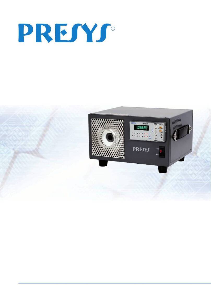
Presys T-1200PH User manual
Presys
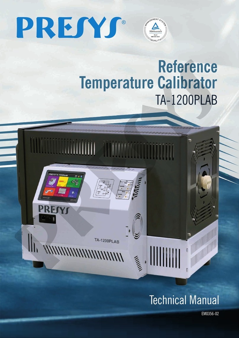
Presys TA-1200PLAB User manual
Presys
Presys PCA-570-RM User manual
Presys
Presys MCS-XV User manual
Presys
Presys PC-507-IS User manual
Presys
Presys T-1200PIR User manual

