Shin-Nippon SLM-5000 User manual

RB-473-C02G
Auto Lensmeter
SLM-5000 SLM-4000
/
Maintenance Manual

RB-473-C02G
Contents
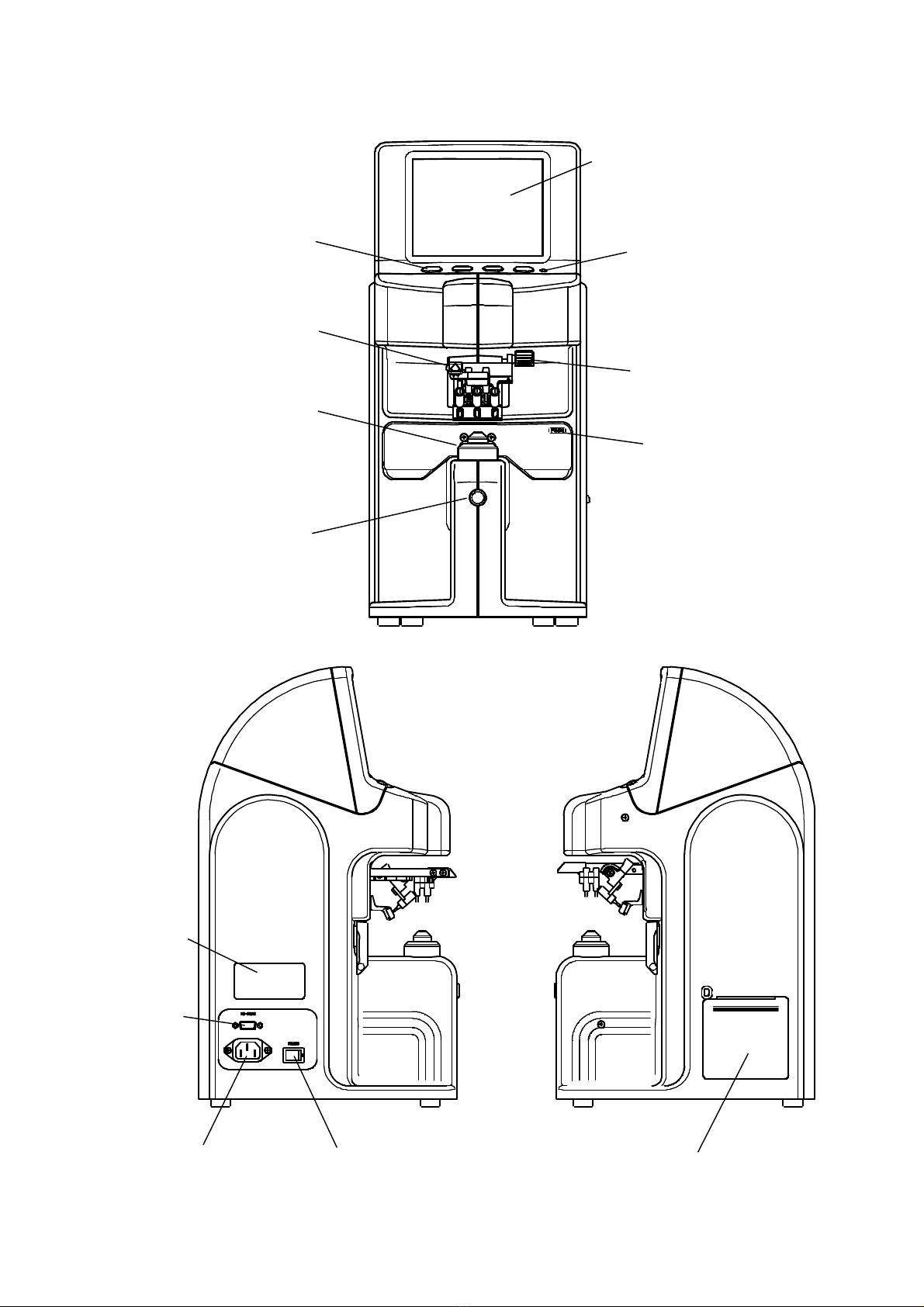
1. External View .....................................................................................................................................................0
2. Exploded View....................................................................................................................................................3
3. Wiring Diagram..................................................................................................................................................4
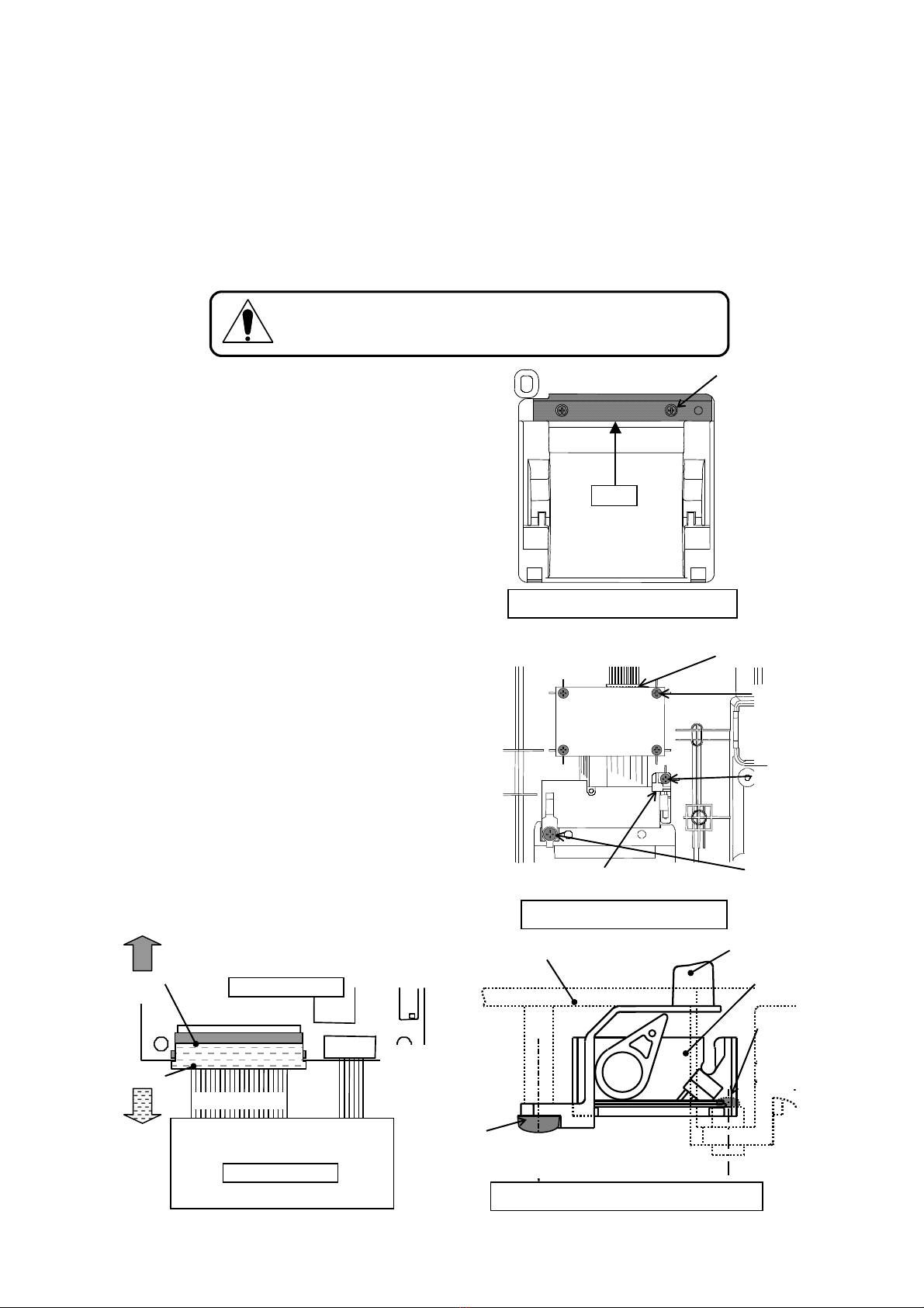
4. Assembly/disassembly of exterior features ........................................................................................................6
4.1. Ink tank holder(※Inkwell specification only)......................................................................................6
4.2. Lens plate....................................................................................................................................................6
4.3. Cases...........................................................................................................................................................6
5. Part replacement .................................................................................................................................................8
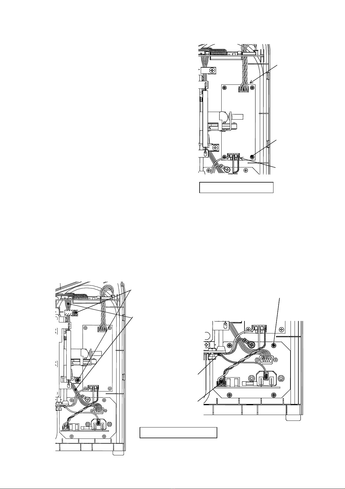
5.1. Control board..............................................................................................................................................8
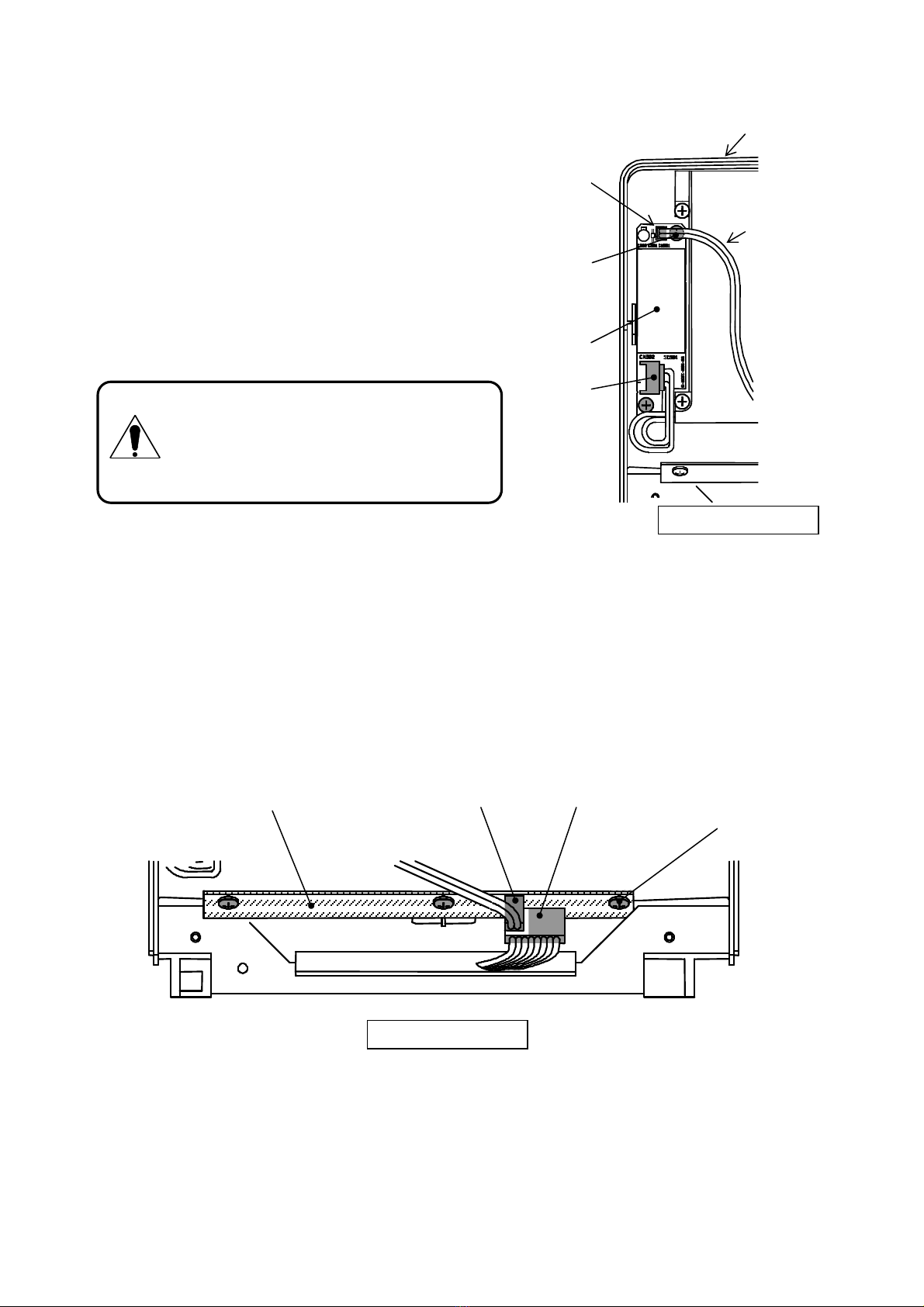
5.2. Printer and printer I/F board .......................................................................................................................8
5.3. LCD monitor...............................................................................................................................................9
5.4. Inverter board............................................................................................................................................11
5.5. Operation switch board.............................................................................................................................11
5.6. Switching power supply ...........................................................................................................................12
5.7. Terminal ASSY.........................................................................................................................................12
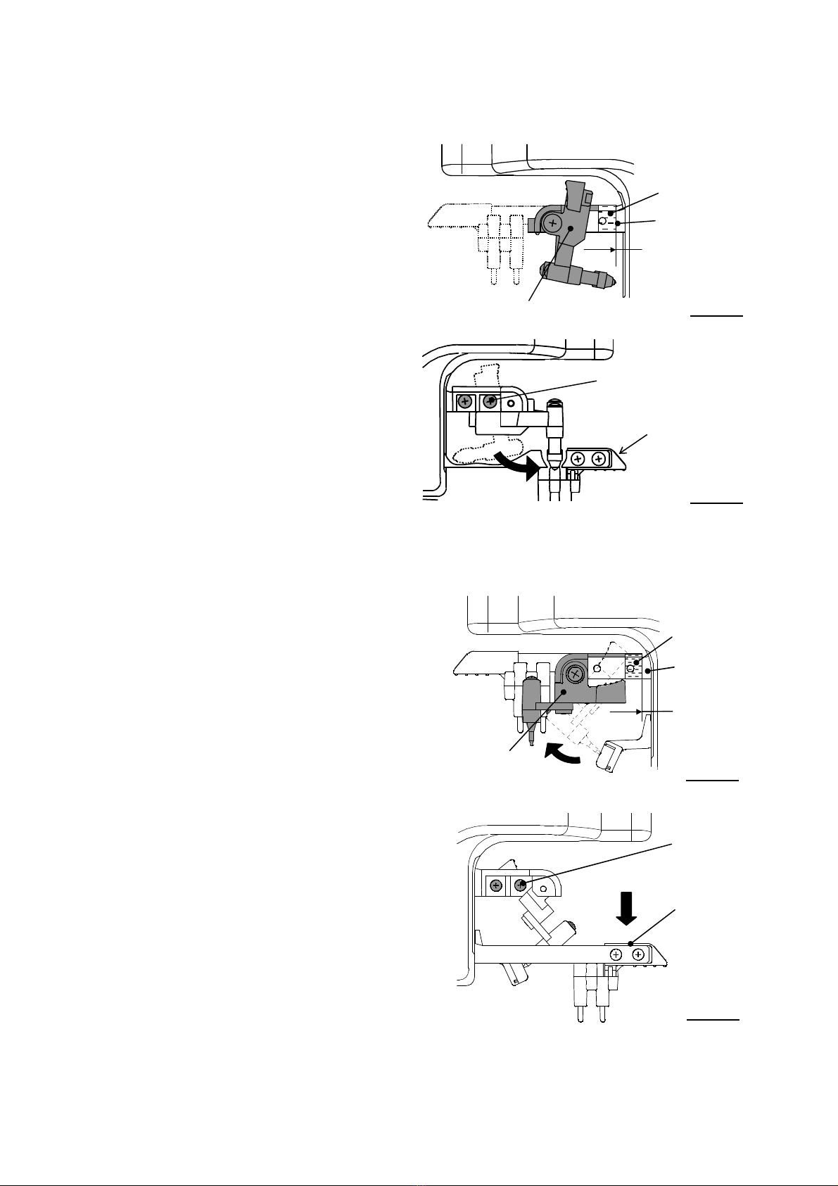
5.8. Marking ASSY..........................................................................................................................................13
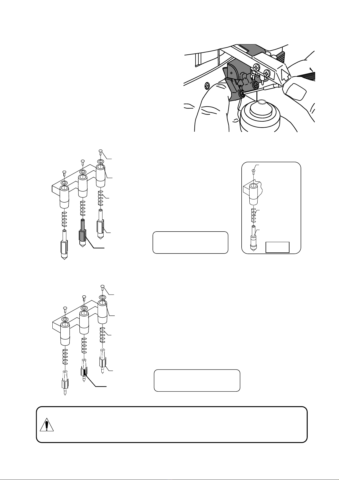
5.9. Marking pen(pin).................................................................................................................................14
5.10. Inkwell(※Inkwell specification only).................................................................................................15
5.11. Lens holder ASSY ....................................................................................................................................15
5.12. Illmination circuit board ASSY ................................................................................................................16
5.13. Heavy motion damper/Light motion damper............................................................................................17
6. Troubleshooting................................................................................................................................................18
6.1. Measures against errors ............................................................................................................................19
6.1.1. Measure Error.................................................................................................................................. 19
6.1.2. Paper Empty..................................................................................................................................... 20
6.1.3. Printer Cover Open.......................................................................................................................... 20
6.1.4. SPH/CYL/Prism/ADD Over............................................................................................................ 21
6.1.5. Printer Heat Over............................................................................................................................. 21
6.1.6. EEPROM Fault, Sensor Error.......................................................................................................... 21
6.1.7. DRAM Error.................................................................................................................................... 22
6.1.8. Retry Error, Notarget Error.............................................................................................................. 22
7. Image assessment..............................................................................................................................................23
7.1 How to engage in Dealer Mode................................................................................................................23
7.2. How to check images................................................................................................................................23
7.3. Image samples ..........................................................................................................................................24
8. Calibration........................................................................................................................................................27
8.1 How to engage in Dealer Mode................................................................................................................27
8.2. Device setting ...........................................................................................................................................28
8.3. How to engage in Calibration screen........................................................................................................29
8.4. Calibration procedure ...............................................................................................................................29
9. Cleaning............................................................................................................................................................33
9.1. Main unit...................................................................................................................................................33
9.2. Optical unit ...............................................................................................................................................33
10. Software change - upgrading............................................................................................................................34
10.1. Preparation................................................................................................................................................34
10.2. Procedure..................................................................................................................................................34
11. Input/output of adjustment data........................................................................................................................36
11.1. Input/output of adjustment data................................................................................................................36
11.2. General-purpose equipment used..............................................................................................................36
11.3. Preparation................................................................................................................................................37
11.4. Output of adjustment data.........................................................................................................................41
11.5. Input of adjustment data ...........................................................................................................................43

RB-473-C02G
1. External View
【Cartridge specification】
Color LCD monitor:SLM-5000
Monochrome LCD monitor:SLM-4000
Operations switches
Indicator
Marking lever
Lens plate
Lens stand
Lens holder
Memory/Add switch
Printer
*SLM-5000 Only
Power switch
Power inlet
RS-232C terminal
Rating nameplate

RB-473-C02G
1
【Inkwell specification】
Color LCD monitor:SLM-5000
Monochrome LCD monitor:SLM-4000
Operations switches Indicator
Marking lever
Lens plate
Lens stand
Lens holder
Memory/Add switch
Printer
*SLM-5000 Only
Power switch
Power inlet
RS-232C terminal
Rating nameplate

RB-473-C02G
2
2. Exploded View
250V 3A (UL/CSA)
T2A L 250V(E UROPE)
250V 3A (UL/CSA)
T2A L 250V(E UROPE)
Terminal Assy
To FG attachment
To FG attachment
Power switch
RS
-
232C
Power inlet
Power switch
Fuse x 2
EUROPE:T2A L 250V
UL/CSA:250V 3A
Printer I/F board
Printer
Connected to *
FG harness
(green
/yellow)
*
Memory/Add
switch board
Terminal Assy
FG attachment
Control
board
LCD
Inverter board
Operation
switch board
Lens hold
er
Marking
CMOS
camera board
E
2
PROM
board
Optical
unit Assy
Printer related parts
*SLM
-
5000 Only

RB-473-C02G
3
3. Wiring Diagram
FG
(green/yellow)
CN402, 20 pins
CN404, 26 pins
CN403, 8 pins
CN501, 16 pins
CN405, 2 pins
CN301, 5 pins
CN401, 4 pins
Illmination circuit
board ASSY
E2PROM board
CN202, 24 pins
CN201, 24 pins
Memory switch
board
CMOS camera board
LCD
CN201, 8 pins
CN202, 2 pins
Operation switch board
Inverter
board
CN301, 2 pins
CN302, 2 pins
Control board
Terminal board
RS-232C
Switching
power supply
CN2, 4 pins
CN1, 5pin
13 5
L(brown)
N(light blue)
1,3
FG(green/yellow)
1
2
3
4
GND (brown)
GND (red)
+5V (orange)
+5V (yellow)
Printer I/F board
CN101, 20pins
CN103, 20 pins
CN102, 9 pins
Flat
cable
Flat c
able
Printer FG
(green/yellow)
FG
(green/yellow)
FG(green/yellow)
Printer related parts
*SLM-5000 Only
【SLM-5000: To SN/Y74763N】
【SLM-4000: To SN/Y74040A】

RB-473-C02G
4
FG
(green/yellow)
CN806,20pin
CN701,30pin
CN703,8pin
CN903,16pin
CN804,2pin
CN601,5pin
CN501,4pin
Illmination circuit
board ASSY
E2PROM board
CN2,30pin
CN3,20pin
Memory switch
board
CMOS camera board
LCD
CN201,8pin
CN202,2pin
Operation switch board
Inverter
board
Control board
Terminal board
RS-232C
スイッチング電源
CN2,4pin
CN1,5pi
n
13 5
L(brown)
N(light blu
e)
1,3
FG(green/yellow)
1234
GND(茶)
GND(赤)
+5V(橙)
+5V(黄)
Printer I/F board
CN101,20pin
CN103,20pin
CN102,9pin
プリンター FG
(green/yellow)
FG (green/yellow)
LCD
CN301,2pin
CN2,4 pin
CN1,5pin
13 5
1,3
1
2
3
4
GND(brown)
GND(red)
+5V (orange)
)
+5V (yellow)
CN102,9pin
Printer
FG
(green/yellow)
Switching
power supply
CN302,2pin
Flat
cable
Flat cable
CN4,2pin
Printer related parts
*SLM-5000 Only
【SLM-5000: From SN/Z74764N】
【SLM-4000: From SN/Z74041A】

RB-473-C02G
5
4. Assembly/disassembly of exterior features
4.1. Ink tank holder(※Inkwell specification only)
・Lower the lens holder. Unscrew the screw securing
the ink tank holder from the front, and remove the
ink tank holder.
4.2. Lens plate
・Unscrew two screws securing the lens plate. (M3 x
L10 binding screws, black)
4.3. Cases
・Remove eight (7) screws securing right and left cases.
Always cut the power and disconnect the power cord
before disassembling the instrument.
Lens plate
Two screws
(Binding
screws,
black, M3 x L10)
Screw:
tapping screw (white),
a nominal dia.: 3, L10
Screw
: tapping screw
(white)
a nominal dia.: 3, L10
Screw:
M3 L8 (white),
in both sides
Four screws,
SUS304
M3 L8
Base
Lens holder
Ink tank holder

RB-473-C02G
6
・Turn the instrument on its side so that the left side when viewed from the front becomes the bottom. Then,
raise the right side up.
Raise firmly.
Do not lose the screws when disassembling the instrument since some
screws are special types.

RB-473-C02G
7
5. Part replacement
5.1. Control board
1) Remove the lens plate and cases. (See '4. Assembly/disassembly of exterior features'.)
2) Remove all connectors connected to the board. (See '2. Exploded View' and '3. Wiring Diagram'.)
3) Replace the board to the new one. Check that all connectors are appropriately connected, and then,
reassemble the lens plate and cases.
5.2. Printer and printer I/F board
(*SLM-5000 Only)
1) Remove the lens plate and cases. (See 4.
Assembly/disassembly of exterior features.)
2) Remove the connector connected to the printer I/F
board. (CN 101 (20 pins))
3) Unscrew two (2) screws A securing the printer onto
the right case of the main unit (outside).
4) Unscrew six (6) screws securing the printer I/F
board and printer onto the right case of the main
unit (inside). Set screw C and a printer open switch
are tightened together.
5) Remove the connectors from the printer I/F board.
Since CN101 of the printer I/F board has a locking
mechanism, unlock it, and then, remove the
harnesses.
Do not pull the wires when you disconnect the connector. The
wire may be cut or damaged.
Main unit case: right (outside)
Printer
Screw A (2):
tapping screws
(black), a nominal
dia.: 2, L8
Printer I/F board
CN101, 20 pins
CN102, 9 pins
(flat cable)
Printer
Lock
Unlock
Printer I/F board
Printer
Main unit case: right (inside)
Screw B (4):
tapping screw,
a nominal dia.: 3, L8
Screw C:
tapping screw,
a nominal dia.: 3, L8
Screw D:
tapping screw,
a nominal dia.: 3, L10
CN101
(
20 pins
)
Printer open switch
Screw A
2:
tapping screw (black)
a nominal dia.: 2, L8
Main unit case: R
Printer open SW
Printer
Screw C: tapping screw
a nominal dia.: 3, L8
Sectional view: printer mounting part

RB-473-C02G
8
6) Replace the roller of the printer cover. Remove two screws E.
Avoid confusing left and right and secure them aligning with the dowel pins.
Screw E (2 points)
M2 L3 (chromium)
Roller
Dowel pin
(2 points)
Printer cover
5.3. LCD monitor
1) Remove the lens plate and cases. (See '4. Assembly/disassembly of exterior features'.)
2) Disconnect the harnesses and FG harness connecting from LCD ASSY to the control board.
・LCD monitor control board
・Switch board control board
(See '2. Exploded View' and '3. Wiring Diagram'.)
3) Unscrew two screws F securing the LCD ASSY and the main unit case L, and remove the LCD ASSY
from the case.
LCD monitor
Inverter board
Operation SW
board
Screw F
2:
tapping screw,
a nominal diameter 4 10L (chromate)
FG harness fixing screw G
M3X8L 3P (brass, nickel)
LCD case D
LCD case C
LCD Assy

RB-473-C02G
9
4) Slide the LCD case C down. The LCD case C and D fitted by three hooks will be unhooked and
separated.
Top center
middle
LCD case D
LCD case C
5) Remove the connector A connected to the LCD and the connector B connected the inverter board. Then,
unscrew four screws securing the LCD monitor. The LCD monitor will be removed from the LCD case C.
LCD monitor Connector A
Connector B
Inverter board
Back of LCD case D
Screw H (4):
tapping screw,
a nominal dia.: 3, L:6
6) Follow the steps above in the reverse order for reassembling.

RB-473-C02G
10
5.4. Inverter board
1) Disassemble the instrument following the
same steps described in '5.3 LCD monitor'.
2) Disconnect the connector A and B from the
inverter board.
3) Remove two screws I to remove the board
from the LCD case D.
4) Follow the steps above in the reverse order to
reassemble the instrument.
5.5. Operation switch board
1) Disassemble the instrument following the same steps described in '5.3 LCD monitor'.
2) Disconnect the connector A and B from the inverter board.
3) Unscrew three screws to remove the board from LCD case D.
4) Follow the steps above in the reverse order to reassemble the instrument.
Connector A
Back of LCD case D
Connector B
To Operation SW
board
Screw I (2):
tapping screw, a
nominal dia.: 3, L8
Inverter board
LCD case D
When the power is turned on, high voltage is
generated from the connector B.
When replacing the inverter board, always cut
the power and unplug the power cord.
Back of LCD case D
Operation SW board
Connector A
Screw J (3):
tapping screw, a
nominal dia.: 3, L8
Connector B

RB-473-C02G
11
5.6. Switching power supply
1) Remove the lens plate and cases.
(See '4. Assembly/disassembly of exterior features'.)
2) Disconnect Connector A and B from the switching
power supply.
3) Unscrew four screws K to remove the switching
power supply from the main unit case: left.
4) Follow the steps above in the reverse order to
reassemble the instrument.
5.7. Terminal ASSY
1) Remove the lens plate and cases. (See '4. Assembly/disassembly of exterior features'.)
2) Unscrew two screws L fixing the clamps binding harness from RS-232C and remove the connector
connected to the control board .
3) Remove FG harness in the Optical ASSY side (Two screws are at the end of green and yellow wires).
4) Disconnect the connector A from the terminal ASSY.
5) Unscrew four screws M to remove the terminal ASSY from the main unit case: left.
6) Follow the steps above in the reverse order to reassemble the instrument.
Main unit case: left (inside)
Switching
power
supply
Connector A
(to the control
board)
Connector B
(to the terminal board)
Screw K (4):
tapping screw,
a nominal
dia.: 3, L8
Screw L (2):
tapping screw,
a nominal dia.:4, L10
To the control board
Main unit case: left (inside)
Screw M (4):
tapping screw, a
nominal dia.: 3, L8
Connector A
FG fixing screw (2):
M4 L8

RB-473-C02G
12
5.8. Marking ASSY
【Cartridge specification】
1) Affix the positioning tape for the marking
ASSY on the marking arm. Refer to Figure
1 on the right for the tape position to be
affixed.
2) Lower the lens holder. (See Figure 2)
Rotate the marking ASSY until two screws N
become visible. Remove the screws.
3) Mount the new marking ASSY and tighten the
screws N aligning with the positioning tape.
【Inkwell specification】
1) Rotate the marking ASSY. Affix the positioning
tape for the marking ASSY on the marking arm.
Refer to Figure 3 on the right for the tape
position to be affixed.
2) Lower the lens holder. Remove two screws N.
(See Figure 4)
3) Mount the new marking ASSY and tighten the
screws N aligning with the positioning tape.
Figure 1
Marking ASSY
Positioning tape
Marking arm
Align the tape
with this position.
Figure 2
Rotate
Screw N (2):
M3
L10 (black)
Lens holder
Figure 4
Marking ASSY
Positioning tape
Figure 3
Marking arm
Align the tape
with this position
Rotate
Lens holder
Screw N (2):
M3
L10 (black)

RB-473-C02G
13
5.9. Marking pen(pin)
1) Hold the pen(pin) tip of the marking pen(pin) (the
plastic part) and turn the screw to the left to remove.
2) Attach the spring to the new marking pen(pin) as
shown in the figure below, and insert it into the
f marking inger.
3) Keep holding the pen(pin) tip (the plastic part) and
lightly fix it with the screw.
【Cartridge specification】
【Inkwellspecification】
Usethe marking pen
(pin)
exclusively designed for SLM
-
5000
/4000
only.
Avoidtouching the pen(pin)
tip when replacing. The tip may be damage so that the marking
can not be done.
Do not fasten the screw too tightly when replacing. You may damage the part.
The screw and spring are the part of the unit. Avoid losing them.
Marking pen
Spring
Screw
(M2.6x5L)
old-type
note
:
A central marking pen
is
black sign addition and
is shorter
than pens on both sides.
Marking pen
Spring
Screw(M2
×
4L)
Black
F
lat washer
a nominal dia:2
Marking pin
Spring
Screw(M2
×
4L)
Black sign
F
lat washer
a nominal dia:2
note
:
A central marking pen
is black and
is shorter than
pens on both sides.

RB-473-C02G
14
5.10. Inkwell(※Inkwell specification only)
1) Slide the inkwell to the side to remove from the main unit.
2) Soak the specified ink into the sponge from the ink refill point.
3) Attach the inkwell to the main unit.
・Always use the specified ink for refill.
・Avoid touching the pen tip during refill.
Inkwell
Inkwell
Ink refill point
Inkwell

RB-473-C02G
15
5.11. Lens holder ASSY
1) Unscrew two screws O.
2) Align the center of the lens stand with that of the
lens holder for replacement as shown on the
figure. Tighten the screws O to secure the lens
holder.
5.12.Illumination circuit board ASSY
1) Disassemble the outer covers. (See Assemble/Disassemble of Outer Cases).
2) Remove two screws P fixing the optical unit ant life the optical unit up slightly.
3) Disconnect the connector inserted into the illumination light PCB ASSY.
4) Remove two screws Q fixing the illumination light PCB ASSY and remove the PCB.
5) Center and fix the illumination light PCB ASSY for replacement with screws Q.
6) Carry out calibration after replacement. (See Calibration.)
Screw O (2):
tapping screw (black)
a nominal dia.: 3, L10
Lens holder
Lens stand
Left side
Illmination
circuit board
ASSY
Fixing screws Px2
Tapping screw nominal
diameter 3x10L
(black)
Optical unit
Fixing screws Qx2
M2xL6 (3P/black)
Illmination
circuit board ASSY
Connector (2P)
(back)
LED
(back)

RB-473-C02G
16
5.13.Heavy motion damper / Light motion damper
1) Disassemble the outer covers. (See Assemble/Disassemble of Outer Cases).
2) Remove two screws fixing the heavy motion damper/Light motion damper and remove the heavy motion
damper/Light motion damper.
3) Follow the steps above in the reverse order to reassemble the instrument.
Heavy motion damper / Light motion damper

RB-473-C02G
17
6. Troubleshooting
Error message Status Description
Measure Error Abnormality of measurement value when the power is turned
on.
Paper Empty* No papers in the printer
Printer Cover Open* The printer cover is open.
Printer Heat Over* Abnormal temperature rise on the printer head
EEPROM Fault
DRAM Error
Device
abnormality
Memory malfunction
SPH Over The measurement result exceeds the measurement range of
SPH.
CYL Over The measurement result exceeds the measurement range of
CYL.
Prism Over The measurement result exceeds the measurement range of
prism.
ADD Over
Measurement
abnormality
The measurement result exceeds the measurement range of
ADD.
Retry Error Unmeasurable due to dust, flaws or unnecessary light.
No target error
Image
processing
abnormality The light-receiving sensor fails to receive the measurement
light.
note:* SLM-5000 Only
Message Status Description
Measure Error When the power is turned, values are not initialized
(values are not zero (0)).
Paper Empty
(SLM-5000 Only)No papers are set in the printer.
Printer Cover Open
(SLM-5000 Only)The printer cover is open.
Printer Heat Over
(SLM-5000 Only)The printer is overheated.
EEPROM Fault Abnormality of memory
Sensor Error Abnormality of camera sensor
Error * * * (100 –141)
Abnormality
of the
instrument
Abnormality of electronic parts (on the 'Control circuit board')
SPH Over SPH value exceeds the measurement range.
CYL Over CYL value exceeds the measurement range.
Prism Over Prism value exceeds the measurement range.
ADD Over
Measurement
abnormality
ADD value exceeds the measurement range.
Retry Error Measurement fails because of dust, flaws, unnecessary light,
and so on.
Notarget Error
Abnormality
of image
processing The measurement light does not enter into the receiving light
sensor.
Display with a three-digit code (number).
【SLM-5000: To SN/Y74763N】
【SLM-4000: To SN/Y74040A】
【SLM-5000: From SN/Z74764N】
【SLM-4000: From SN/Z74041A】
Other manuals for SLM-5000
1
This manual suits for next models
5
Table of contents
Other Shin-Nippon Measuring Instrument manuals