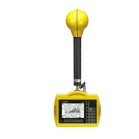
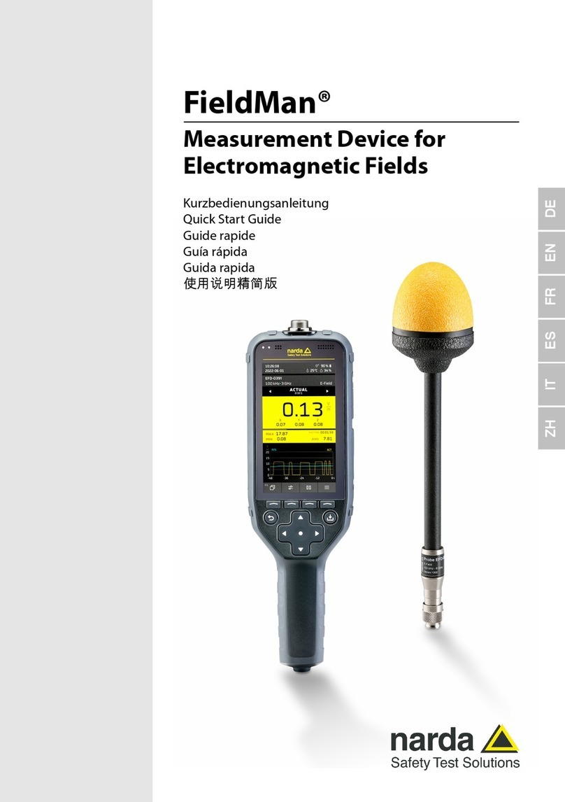
NARDA EFA-200 User manual

EFA-200/-300
EM Field Analyzer
Operating Manual
2245/98.22


EFA-200/-300
EM Field Analyzer
2245/20, 30, Series A ...
Operating Manual

If you have any questions
about this product, please contact
the Sales Company for your locality.
Narda Safety Test Solutions GmbH
Sandwiesenstr. 7
72793 Pfullingen, Germany
© 2006
Order no.: 2245/98.22
Edition: 05/06.03, A ...
Previous Edition: 04/05.03, A ...
Subject to change without notice.
Our normal guarantee and delivery
terms apply.
Printed in Germany

CONTENTS
1Introduction
1.1 About these instruments . . . . . . . . . . . . . . . . . . . 1-1
1.1.1 Applications . . . . . . . . . . . . . . . . . . . . . . . . . . . . . 1-1
1.1.2 Common features . . . . . . . . . . . . . . . . . . . . . . . . 1-1
1.1.3 Differing features . . . . . . . . . . . . . . . . . . . . . . . . . 1-2
1.2 About this operating manual . . . . . . . . . . . . . . . . 1-3
2 Safety instructions
2.1 Before connecting up . . . . . . . . . . . . . . . . . . . . . 2-1
2.2 Correct use . . . . . . . . . . . . . . . . . . . . . . . . . . . . . 2-1
2.3 AC Power Supply Unit. . . . . . . . . . . . . . . . . . . . . 2-2
2.4 Faults and excessive stresses . . . . . . . . . . . . . . 2-3
3 Preparation for use
3.1 Unpacking . . . . . . . . . . . . . . . . . . . . . . . . . . . . . . 3-1
3.1.1 Packaging . . . . . . . . . . . . . . . . . . . . . . . . . . . . . . 3-1
3.1.2 Checking the package contents . . . . . . . . . . . . . 3-1
3.1.3 Checking for transport damage . . . . . . . . . . . . . . 3-1
3.1.4 Recovery after transport and storage . . . . . . . . . 3-1
3.2 Power supply. . . . . . . . . . . . . . . . . . . . . . . . . . . . 3-2
3.2.1 Operation from rechargeable batteries / dry cells 3-2
3.2.2 Charging the rechargeable batteries . . . . . . . . . . 3-3
3.3 Preparing for B-field measurements . . . . . . . . . . 3-4
3.3.1 Measurement setup. . . . . . . . . . . . . . . . . . . . . . . 3-4
3.3.2 Selecting the probe type . . . . . . . . . . . . . . . . . . . 3-4
3.3.3 Connecting / disconnecting the external
B-Field Probe . . . . . . . . . . . . . . . . . . . . . . . . . . . 3-5
3.3.4 Switching on the Basic Unit. . . . . . . . . . . . . . . . . 3-5
3.4 Preparing for E-field measurements . . . . . . . . . . 3-8

3.4.1 Measurement setup . . . . . . . . . . . . . . . . . . . . . . . 3-8
3.4.2 Assembling the E-Field Unit measurement
setup. . . . . . . . . . . . . . . . . . . . . . . . . . . . . . . . . . 3-10
3.4.3 E-Field Unit function test . . . . . . . . . . . . . . . . . . 3-10
4 Control and display elements
4.1 Basic Unit keyboard . . . . . . . . . . . . . . . . . . . . . . . 4-1
4.2 Basic Unit display . . . . . . . . . . . . . . . . . . . . . . . . . 4-5
4.2.1 Liquid crystal display . . . . . . . . . . . . . . . . . . . . . . 4-5
4.2.2 Backlight. . . . . . . . . . . . . . . . . . . . . . . . . . . . . . . . 4-5
4.2.3 Contrast . . . . . . . . . . . . . . . . . . . . . . . . . . . . . . . . 4-5
4.3 Basic Unit indicators. . . . . . . . . . . . . . . . . . . . . . . 4-6
4.4 E-Field Unit controls . . . . . . . . . . . . . . . . . . . . . .4-7
5 Selecting an operating mode
5.1 Operating mode applications . . . . . . . . . . . . . . . . 5-1
5.2 Operating mode features . . . . . . . . . . . . . . . . . . . 5-2
5.2.1 Field Strength mode . . . . . . . . . . . . . . . . . . . . . . .5-2
5.2.2 Exposure STD mode (Shaped Time Domain) . . . 5-3
5.2.3 Spectrum FFT mode
(Fast Fourier Transformation). . . . . . . . . . . . . . . . 5-4
5.2.4 Harmonic Analysis mode . . . . . . . . . . . . . . . . . . .5-5
5.3 Checking the EFA operating modes. . . . . . . . . . .5-6
6 Operating modes
6.1 Field Strength mode . . . . . . . . . . . . . . . . . . . . . . .6-1
6.1.1 Activating Field Strength mode. . . . . . . . . . . . . . . 6-2
6.1.2 Selecting the measurement range . . . . . . . . . . . .6-2
6.1.3 Selecting the detection mode . . . . . . . . . . . . . . . .6-3
6.1.4 Selecting the display mode . . . . . . . . . . . . . . . . . 6-4
6.1.5 Selecting the frequency range . . . . . . . . . . . . . . .6-4
6.1.6 Evaluating the results . . . . . . . . . . . . . . . . . . . . . . 6-6

6.1.7 Saving data . . . . . . . . . . . . . . . . . . . . . . . . . . . . . 6-8
6.2 Exposure STD mode (Shaped Time Domain). . . 6-9
6.2.1 Activating STD mode. . . . . . . . . . . . . . . . . . . . . . 6-9
6.2.2 Selecting the measurement range . . . . . . . . . . . 6-9
6.2.3 Selecting the display mode . . . . . . . . . . . . . . . . 6-10
6.2.4 Frequency range . . . . . . . . . . . . . . . . . . . . . . . . 6-10
6.2.5 Evaluating the results . . . . . . . . . . . . . . . . . . . . 6-10
6.2.6 Saving data . . . . . . . . . . . . . . . . . . . . . . . . . . . . 6-12
6.3 Spectrum FFT mode . . . . . . . . . . . . . . . . . . . . . 6-13
6.3.1 Activating Spectrum FFT mode . . . . . . . . . . . . . 6-13
6.3.2 Selecting the measurement range . . . . . . . . . . 6-14
6.3.3 Selecting the measurement mode
(detection mode) . . . . . . . . . . . . . . . . . . . . . . . . 6-15
6.3.4 Selecting the display mode . . . . . . . . . . . . . . . . 6-15
6.3.5 Selecting the frequency range. . . . . . . . . . . . . . 6-16
6.3.6 Starting and stopping a measurement. . . . . . . . 6-17
6.3.7 Evaluating measurement results . . . . . . . . . . . . 6-17
6.3.7.1 Zooming in on the frequency axis . . . . . . . . . . . 6-20
6.3.7.2 Zooming in on the measured value axis . . . . . . 6-21
6.3.7.3 Marker . . . . . . . . . . . . . . . . . . . . . . . . . . . . . . . . 6-22
6.3.7.4 Normalized display . . . . . . . . . . . . . . . . . . . . . . 6-24
6.3.8 Saving data . . . . . . . . . . . . . . . . . . . . . . . . . . . . 6-25
6.3.9 Possible problems . . . . . . . . . . . . . . . . . . . . . . . 6-25
6.4 Harmonic analysis mode . . . . . . . . . . . . . . . . . . 6-26
6.4.1 Activating Harmonic Analysis mode . . . . . . . . . 6-26
6.4.2 Selecting the measurement range . . . . . . . . . . 6-27
6.4.3 Selecting the measurement mode
(detection mode) . . . . . . . . . . . . . . . . . . . . . . . . 6-28
6.4.4 Selecting the display mode . . . . . . . . . . . . . . . . 6-28
6.4.5 Selecting the fundamental frequency . . . . . . . . 6-29
6.4.6 Starting and stopping a measurement. . . . . . . . 6-30

6.4.7 Evaluating measurement results . . . . . . . . . . . . 6-31
6.4.8 Saving data. . . . . . . . . . . . . . . . . . . . . . . . . . . . . 6-34
6.4.9 Possible problems . . . . . . . . . . . . . . . . . . . . . . . 6-34
7 Measurement data memory
7.1 Saving data. . . . . . . . . . . . . . . . . . . . . . . . . . . . . . 7-1
7.1.1 Saving individual values . . . . . . . . . . . . . . . . . . . . 7-2
7.1.2 Recording timer-controlled measurement
sequences (AUTO). . . . . . . . . . . . . . . . . . . . . . . .7-3
7.1.3 Recording spatially assigned measurement
sequences (MATRIX) . . . . . . . . . . . . . . . . . . . . . . 7-7
7.2 Displaying a data set . . . . . . . . . . . . . . . . . . . . . 7-14
7.3 Exporting data . . . . . . . . . . . . . . . . . . . . . . . . . . 7-16
7.4 Deleting data . . . . . . . . . . . . . . . . . . . . . . . . . . . 7-18
8 Optional functions
8.1 Selecting an alarm . . . . . . . . . . . . . . . . . . . . . . . . 8-1
8.1.1 Activating the “ALARM” function . . . . . . . . . . . . . 8-1
8.1.2 Entering the alarm threshold . . . . . . . . . . . . . . . .8-2
8.1.3 Activating alarm signals . . . . . . . . . . . . . . . . . . . .8-2
8.2 Recording current values . . . . . . . . . . . . . . . . . . . 8-4
8.2.1 Activating the CURRENT function . . . . . . . . . . . . 8-4
8.2.2 Entering current values . . . . . . . . . . . . . . . . . . . . 8-4
8.2.3 Activating recording of current values . . . . . . . . .8-5
8.3 Choosing a limit curve . . . . . . . . . . . . . . . . . . . . .8-5
8.4 Selecting the measurement axis . . . . . . . . . . . . .8-6
8.5 Selecting the measurement units . . . . . . . . . . . . .8-7
8.6 Setting the averaging parameter NAVG . . . . . . . . 8-7
8.7 Editing the frequency selection list . . . . . . . . . . . . 8-8
8.7.1 Activating the “FREQ LISTS” function . . . . . . . . . 8-8
8.7.2 Changing the frequency values . . . . . . . . . . . . . . 8-8
8.8 Setting the date and time . . . . . . . . . . . . . . . . . . .8-9

8.8.1 Activating the “CLOCK” function . . . . . . . . . . . . . 8-9
8.8.2 Setting the current time . . . . . . . . . . . . . . . . . . . 8-10
8.8.3 Setting the date . . . . . . . . . . . . . . . . . . . . . . . . . 8-10
9 Device data memory
9.1 Calling up a device setting (User Setup) . . . . . . . 9-1
9.2 Scope and content of the default settings
(Factory Default Setup) . . . . . . . . . . . . . . . . . . . . 9-1
9.3 Saving device settings (User Setup) . . . . . . . . . . 9-4
10 Maintenance and repairs
10.1 Dry cells and rechargeable batteries. . . . . . . . . 10-1
10.1.1 Replacing the rechargeable batteries / dry cells 10-1
10.1.2 Handling rechargeable batteries . . . . . . . . . . . . 10-3
10.1.3 Lithium battery. . . . . . . . . . . . . . . . . . . . . . . . . . 10-3
10.1.4 Battery disposal. . . . . . . . . . . . . . . . . . . . . . . . . 10-4
10.2 Software update . . . . . . . . . . . . . . . . . . . . . . . . 10-4
10.2.1 Installing the software “EFA-200/-300 Tools”. . . 10-5
10.2.2 Setting up the EFA – PC connection . . . . . . . . . 10-6
10.2.3 Loading the device firmware . . . . . . . . . . . . . . . 10-6
10.3 Transferring STANDARDS parameters . . . . . . . 10-8
10.4 Enabling operating modes. . . . . . . . . . . . . . . . . 10-9
10.4.1 Entering the access code . . . . . . . . . . . . . . . . 10-10
10.5 Reading out the device characteristics . . . . . . 10-11
10.6 Cleaning . . . . . . . . . . . . . . . . . . . . . . . . . . . . . 10-12
10.7 Power Supply Unit . . . . . . . . . . . . . . . . . . . . . 10-13
10.7.1 Opening the device . . . . . . . . . . . . . . . . . . . . . 10-13
10.7.2 Repairs . . . . . . . . . . . . . . . . . . . . . . . . . . . . . . 10-13
10.7.3 Spare parts . . . . . . . . . . . . . . . . . . . . . . . . . . . 10-13

11 Remote control
11.1 Abbreviations used . . . . . . . . . . . . . . . . . . . . . . . 11-1
11.2 Making the connection from EFA to PC . . . . . . . 11-1
11.3 Structure of device-specific commands . . . . . . . 11-3
11.4 Remote control commands . . . . . . . . . . . . . . . . 11-7
11.4.1 Measurement settings . . . . . . . . . . . . . . . . . . . . 11-8
11.4.2 Reading out current measurement values . . . . 11-12
11.4.3 Measurement data memory . . . . . . . . . . . . . . . 11-16
11.4.4 Optional functions. . . . . . . . . . . . . . . . . . . . . . . 11-22
11.4.5 General functions . . . . . . . . . . . . . . . . . . . . . . . 11-28
11.4.6 Test / Service . . . . . . . . . . . . . . . . . . . . . . . . . . 11-28
12 Specifications
12.1 Principle of operation . . . . . . . . . . . . . . . . . . . . . 12-1
12.2 Field Strength mode . . . . . . . . . . . . . . . . . . . . . .12-1
12.2.1 Brief description . . . . . . . . . . . . . . . . . . . . . . . . . 12-1
12.2.2 Frequency range . . . . . . . . . . . . . . . . . . . . . . . . 12-2
12.2.3 Measurement range, dynamic range . . . . . . . . . 12-2
12.2.4 Measured value detection . . . . . . . . . . . . . . . . . 12-4
12.2.5 Averaging time / Refresh rate. . . . . . . . . . . . . . . 12-5
12.2.6 Measurement uncertainty . . . . . . . . . . . . . . . . . . 12-5
12.2.7 Result display . . . . . . . . . . . . . . . . . . . . . . . . . . . 12-6
12.2.8 Frequency measurement
(Broadband setting only) . . . . . . . . . . . . . . . . . . 12-6
12.2.9 Auxiliary functions . . . . . . . . . . . . . . . . . . . . . . . 12-6
12.3 Exposure STD (Shaped Time Domain) mode . . 12-7
12.3.1 Brief description . . . . . . . . . . . . . . . . . . . . . . . . . 12-7
12.3.2 Frequency range . . . . . . . . . . . . . . . . . . . . . . . . 12-7
12.3.3 Measurement range, dynamic range . . . . . . . . . 12-7
12.3.4 Limit value curves. . . . . . . . . . . . . . . . . . . . . . . . 12-8
12.3.5 Measurement value detection . . . . . . . . . . . . . . 12-9

12.3.6 Averaging time / Refresh rate . . . . . . . . . . . . . . 12-9
12.3.7 Measurement uncertainty . . . . . . . . . . . . . . . . . 12-9
12.3.8 Result display . . . . . . . . . . . . . . . . . . . . . . . . . 12-10
12.3.9 Additional functions . . . . . . . . . . . . . . . . . . . . . 12-10
12.4 Spectrum FFT . . . . . . . . . . . . . . . . . . . . . . . . . 12-10
12.4.1 Brief description. . . . . . . . . . . . . . . . . . . . . . . . 12-10
12.4.2 Frequency range . . . . . . . . . . . . . . . . . . . . . . . 12-11
12.4.3 Measurement range . . . . . . . . . . . . . . . . . . . . 12-11
12.4.4 Recording of measured values . . . . . . . . . . . . 12-14
12.4.5 Averaging / measured value rate . . . . . . . . . . 12-14
12.4.6 Result display . . . . . . . . . . . . . . . . . . . . . . . . . 12-15
12.4.7 Additional functions . . . . . . . . . . . . . . . . . . . . . 12-15
12.5 Harmonic Analysis mode. . . . . . . . . . . . . . . . . 12-15
12.5.1 Brief description. . . . . . . . . . . . . . . . . . . . . . . . 12-16
12.5.2 Frequency range . . . . . . . . . . . . . . . . . . . . . . . 12-16
12.5.3 Result display . . . . . . . . . . . . . . . . . . . . . . . . . 12-16
12.6 Miscellaneous . . . . . . . . . . . . . . . . . . . . . . . . . 12-17
12.6.1 Display type and warning devices . . . . . . . . . . 12-17
12.6.2 Data memory. . . . . . . . . . . . . . . . . . . . . . . . . . 12-17
12.6.2.1 Brief description. . . . . . . . . . . . . . . . . . . . . . . . 12-18
12.6.2.2 Memory capacity . . . . . . . . . . . . . . . . . . . . . . . 12-18
12.6.2.3 Clock . . . . . . . . . . . . . . . . . . . . . . . . . . . . . . . . 12-18
12.6.3 Device settings memory . . . . . . . . . . . . . . . . . 12-19
12.6.4 Self test . . . . . . . . . . . . . . . . . . . . . . . . . . . . . . 12-19
12.6.5 Remote control interface (serial) . . . . . . . . . . . 12-19
12.6.6 Power supply. . . . . . . . . . . . . . . . . . . . . . . . . . 12-20
12.6.6.1 Battery operation . . . . . . . . . . . . . . . . . . . . . . . 12-20
12.6.6.2 Charger unit. . . . . . . . . . . . . . . . . . . . . . . . . . . 12-21
12.7 General specifications . . . . . . . . . . . . . . . . . . . 12-21
12.7.1 Climatic environment conditions . . . . . . . . . . . 12-21
12.7.2 Conformance marks . . . . . . . . . . . . . . . . . . . . 12-22

12.7.3 Declaration of origin . . . . . . . . . . . . . . . . . . . . . 12-22
12.7.4 Maintenance. . . . . . . . . . . . . . . . . . . . . . . . . . . 12-22
12.7.4.1 Calibration interval . . . . . . . . . . . . . . . . . . . . . . 12-22
12.7.4.2 Data memory battery (lithium battery) . . . . . . . 12-23
12.8 Dimensions and weight . . . . . . . . . . . . . . . . . . 12-23
12.9 Ordering information. . . . . . . . . . . . . . . . . . . . . 12-23
12.9.1 Options . . . . . . . . . . . . . . . . . . . . . . . . . . . . . . . 12-24
Annex A: Glossary
Annex B: Determining the matrix
Annex C: Fundamentals of FFT
Annex D: Data export format
Index

Selecting an
operating mode
Measurement
Activating an
Measurement
data memory
Device
data memory
Chap. 6
Chap. 6
Chap. 7
Chap. 8
Chap. 9
Chap. 5
Chap. 3.3
Chap. 3.4
operating mode
Further
settings
Operating concept


1-1
1 Introduction
1.1 About these instruments
1.1.1 Applications
Many people live and work in the vicinity of power lines and power
distribution equipment. For safety’s sake, it must be ensured that these
people are not exposed to any electromagnetic fields that could be injurious
to health.
Global efforts to introduce effective protection in recent years have led to a
range of national and international guidelines and standards. These set
permitted limit values for electric and magnetic field strengths for various
frequency ranges and signal shapes.
In practice, this means using simple equipment to measure the fields that
occur at a particular location or place of work with sufficient accuracy to
check the effectiveness of protective measures, ensure that the limit values
stipulated by the standards and guidelines are not exceeded and to dispel
any doubts in the minds of those affected. Lightweight, portable, battery-
operated measuring instruments, which cover the dynamic range and
frequencies of interest are needed for this. They must also be easy to use
and deliver results that can be directly compared with the current limit
values.
1.1.2 Common features
The EFA-200 and EFA-300 Field Analyzers are devices for monitoring low-
frequency fields in the range 5 Hz to 32 kHz.
All instrument functions are designed for ease of use under practical
conditions. Operation has been arranged so that the instruments can be set
as simply as possible using function keys and menu keys. Menu keys are
used to switch between the four main menus: MODE, CONFIGURATION,
MEMORY and USER.
The MODE key thus gives access to up to 5 different operating modes.
These modes can be activated individually at any time as needed, so you
can always adapt your EFA to the specific task at hand.

1 Introduction EFA-200/-300
1-2
The MEM key allows you to record a timer-controlled set of measurements
or to save the measured values in a spatial matrix, and to recall the stored
results as required.
The CONF key enables access to additional functions such as activation of
an alarm, entry of date and time information or the selection of stored limit
value curves.
Function keys are used in all menus to enable access to further
measurement functions.
By default, the parameters set the last time the instrument was used are set
automatically when you switch on again. You can continue measuring
straight away. You can also save your own settings under any name and
recall these as required using the USER key.
1.1.3 Differing features
The main differences between the EFA-200 and EFA-300 result from the
different measurement objectives. They are readily apparent from the
different measurement setups that are used.
EFA-200 – magnetic field measurements
The EFA-200 is for measuring magnetic fields.
The measurement setup consists of the Basic Unit and a B-field probe. One
B-field probe is already built in to the Basic Unit. Two external B-field probes
of different designs are available for making more accurate measurements.
EFA-300 – electric and magnetic field measurements
The EFA-300 additionally measures electric fields.
The measurement setup also includes a Basic Unit, which is identical to the
B-field measuring instrument as regards function and operation. An internal
B-field probe is also fitted and the same external probes can also be used.
E-field measurements become possible when the cube-shaped E-Field Unit
– a precisely aligned plate condenser – is connected. The connection
between the Basic Unit and the E-Field Unit is a fiber optic cable. This
allows the highly-sensitive E-Field Unit to be operated from a distance to
ensure that the effects on the field caused by the operator do not influence
the measurement.

EFA-200/-300 1 Introduction
1-3
In this measurement setup, the Basic Unit is only used to operate the
E-Field Unit. The E-Field Unit performs all measurement functions and also
stores the results independently of the Basic Unit. This unusual solution
makes it possible to start a long-term measurement with the E-Field Unit
and then to disconnect the Basic Unit and the fiber optic cable and make
magnetic field measurements using the Basic Unit without the E-Field Unit.
1.2 About this operating manual
The two device types EFA-200 and EFA-300 differ in their measurement
objectives (magnetic flux density or electric field strength). However,
operation of the devices is to a large extent identical since the basic
functions of the EFA-300 and EFA-200 are the same.
This is why it is possible to include both devices in a single operating
manual and consider the two side by side. Important differences in handling
and specifications are covered in the chapters “Preparation for use”,
“Control and display elements” and “Specifications”.
Major differences are found, however, in chapters 5 to 9, which consider the
operation of the devices.
In these chapters, indications that apply to both units refer to the common
name of EFA.
Functions or restrictions that apply to only one of the instruments are
preceded by an appropriate note, e.g. For EFA-200 only.
Restrictions in function are also preceded by appropriate notes. For
example, some of the types of data set cannot be saved as individual values
in the memory. The section “Saving individual values” is therefore prefixed
with the note: For data set types Normal, List, Vector only.

1 Introduction EFA-200/-300
1-4
Notes:

2-1
2 Safety instructions
2.1 Before connecting up
This instrument left the factory in perfect condition. To ensure safe usage
and to preserve it in good condition, please follow the safety instructions
below.
2.2 Correct use
The instrument must only be used under the conditions and for the
purposes for which it was designed.
Danger
Electric shock
The EFA range of instruments is not provided with any special insulation
features.
⇒Do not touch any parts carrying dangerous voltages with the measuring
instrument or the probe.
Strong fields
Very strong fields occur in the vicinity of powerful radiation sources.
⇒Persons fitted with electronic implants (pacemakers, etc.) must avoid
such areas.
Danger of explosion
Alkaline batteries can explode if you attempt to recharge them.
⇒Before starting to recharge the batteries, make sure that rechargeable
cells and not alkaline batteries are fitted in the battery compartment.
⇒Check that the switch inside the battery compartment is set correctly.

2 Safety instructions EFA-200/-300
2-2
2.3 AC Power Supply Unit
Caution
Malfunction
The accuracy and function of the instrument can be impaired by incorrect
use, damage and unauthorized repairs.
⇒Only use the instrument under the conditions and for the purposes for
which it was designed.
⇒Regularly check the instrument for any signs of damage.
⇒Only allow repairs to be made by trained service engineers.
Unsuitable measuring range
The EFA series of instruments has a limited frequency range that extends
from 5 Hz up to 32 kHz. Fields outside this range will normally be assessed
incorrectly.
⇒Select a suitable measuring range.
⇒Only measure within the valid measuring ranges.
Danger
Electric shock
Parts carrying live voltages, which may cause injury can be exposed if the
Power Supply Unit is damaged.
⇒Never use a damaged Power Supply Unit.
Caution
Damage
Incorrect AC line voltages, condensation, extreme temperatures and poor
ventilation can all result in damage to the Power Supply Unit.
⇒Before connecting up the Power Supply Unit check that the operating
voltage of the Power Supply Unit matches the local AC line voltage.
⇒Do not use a Power Supply Unit if condensation has formed on it. If
condensation is unavoidable, such as when the Power Supply Unit is
cold and is brought into a warmer environment, it must be allowed to dry
out completely before it is connected up.
⇒Only use the Power Supply Unit indoors at temperatures between +5 °C
and +45 °C.
⇒Ensure adequate ventilation for cooling during operation.
This manual suits for next models
1
Table of contents
Other NARDA Measuring Instrument manuals

NARDA
NARDA AMB-8059 User manual

NARDA
NARDA 8061 User manual

NARDA
NARDA AMS-8063 Series User manual

NARDA
NARDA SRM-3006 User manual

NARDA
NARDA PMM CA0010 User manual

NARDA
NARDA SRM-3006 User manual

NARDA
NARDA AMS-8061 User manual

NARDA
NARDA SignalShark 3310 User manual

NARDA
NARDA 8718 User manual

NARDA
NARDA NBM-550 User manual

NARDA
NARDA SRM-3000 User manual

NARDA
NARDA FieldMan User manual

NARDA
NARDA nbm-520 User manual

NARDA
NARDA IDA User manual

NARDA
NARDA ESM-10 RadMan Mobile User manual

NARDA
NARDA NIM-511 User manual

NARDA
NARDA EHP-50F User manual

NARDA
NARDA nbm-520 User manual

NARDA
NARDA PMM 6600 User manual

NARDA
NARDA 8718B User manual