Barnstead Thermolyne Corporation Lab-Line 4628 User manual

-~
ARTISAN
®
~I
TECHNOLOGY
GROUP
Your definitive source
for
quality
pre-owned
equipment.
Artisan Technology
Group
Full-service,
independent
repair
center
with
experienced
engineers
and
technicians
on staff.
We
buy
your
excess,
underutilized,
and
idle
equipment
along
with
credit
for
buybacks
and
trade-ins
.
Custom
engineering
so
your
equipment
works
exactly as
you
specify.
•
Critical
and
expedited
services
•
Leasing
/
Rentals/
Demos
• In
stock/
Ready-to-ship
•
!TAR-certified
secure
asset
solutions
Expert
team
ITrust
guarantee
I
100%
satisfaction
All
tr
ademarks,
br
a
nd
names, a
nd
br
a
nd
s a
pp
earing here
in
are
th
e property of
th
e
ir
r
es
pecti
ve
ow
ner
s.
Find the Thermo / Lab-Line / Barnstead 4628 at our website: Click HERE

2/00
OPERATION MANUAL
MANUAL NO. 056-986-00
REV. NO. E
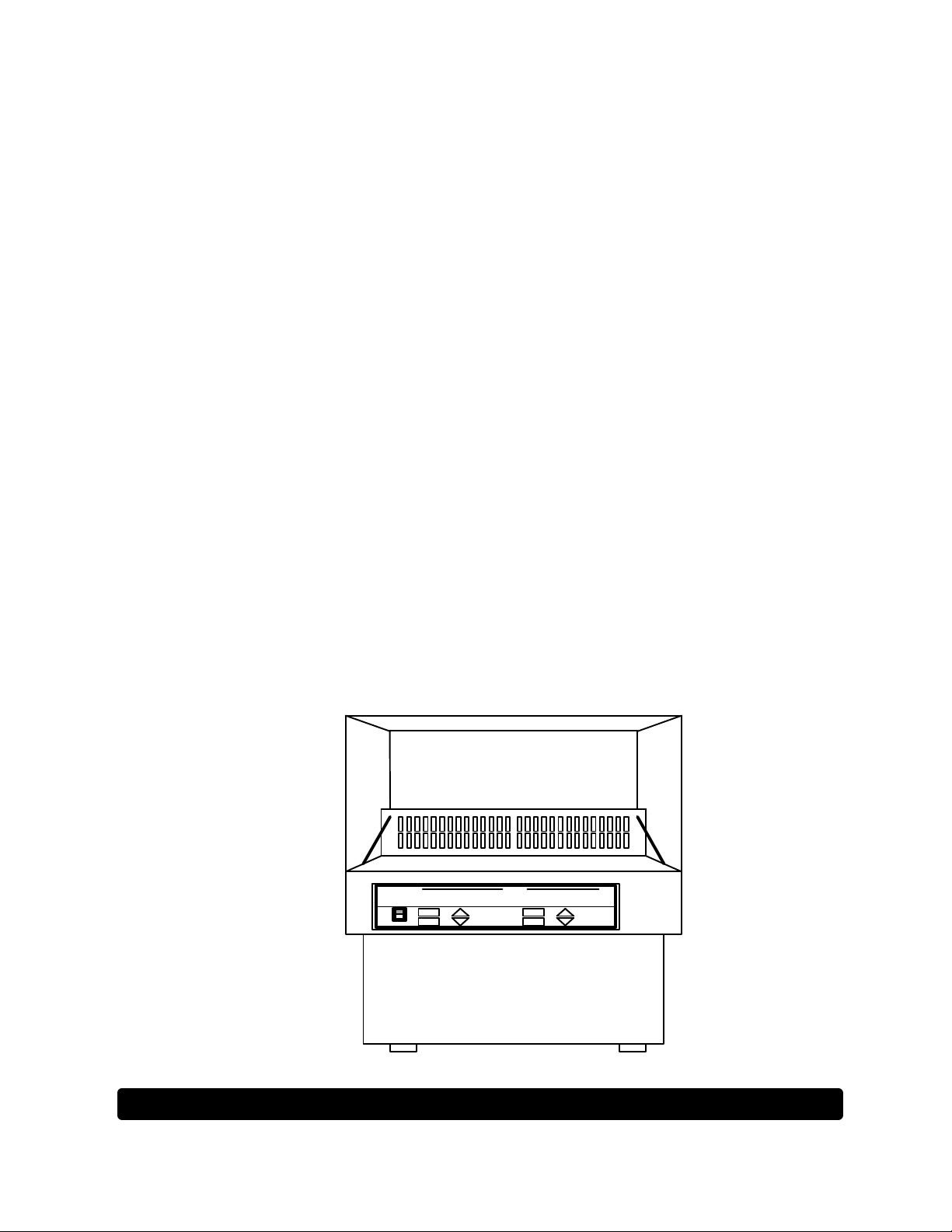
LAB-LINE®
THE FORCE DIGITAL BENCH TOP
INCUBATED SHAKERS
MODELS NOs.
4628,
4628-1,
4628-1CE,
4628-5JPN
ACCESSORIES:
CC: COOLING COIL
(FACTORY
INSTALLED)
GM: GASSING
MANIFOLD
(FACTROY
INSTALLED)
4628-40: LIGHT BANK
(120V, 60 Hz)
4628-41: LIGHT BANK
(240V, 50)
DESIGNERS AND MANUFACTURERS
A SUBSIDIARY of Barnstead|Thermolyne
1999 North 15th Ave., Melrose Park, IL 60160-1491 USA
PHONE: (319) 556-2241 or (800) 522-5463; FAX: (319) 589-0516
Artisan Technology Group - Quality Instrumentation ... Guaranteed | (888) 88-SOURCE | www.artisantg.com

2
TABLE OF CONTENTS
SECTION TITLE
1Introduction
2 Safe Operation
3Description
4 Specifications
5Features
6Installation
7 Operation
8Maintenance
9Replacement Parts
Warranty
Artisan Technology Group - Quality Instrumentation ... Guaranteed | (888) 88-SOURCE | www.artisantg.com

3
SECTION 1
INTRODUCTION
THANK YOU
for selecting Lab-Line Instruments for your equipment needs. For maximum value and
ease of start-up,
PLEASE PROCEED AS FOLLOWS:
?Inspect the carton and contents for shipping damage. Notify the carrier immediately
if damage is found.
?Use the Accessory Checklist when unpacking to verify that the complete unit has
been received. Do not discard packing materials until all is accounted for.
?Read this Operation Manual thoroughly before deciding upon an appropriate
location for the unit: you will want to consider the availability of power, water, hook-
ups, drains and other unit requirements, as well as user convenience.
?Insist that every operator of this unit becomes familiar with the Operation section of
this manual.
?Be sure to fill out the Warranty Registration Card and mail it in to Lab-Line
Instruments within seven (7) days after receiving the unit.
IF
after reading this manual you should have any difficulties with the installation or
operation instructions, please call:
Lab-Line Customer Relations Department
(319) 556-2241 or (800) 522-5463
ALL RIGHT RESERVED
The information contained in this manual is the exclusive property of Lab-Line Instruments, Inc., and has been pro-
vided solely to enable the users of the equipment described herein to operate and maintain such equipment. Any
other use of this information, or the reproduction or transmission of all or any portion of this manual without prior
written consent of the manufacturer is expressly prohibited. © 2000, Lab-Line Instruments, Inc.
Artisan Technology Group - Quality Instrumentation ... Guaranteed | (888) 88-SOURCE | www.artisantg.com

4
SECTION 2
SAFE OPERATION
BE ADVISED:
THE INSTRUCTIONS ON THIS AND THE FOLLOWING PAGE ARE PROVIDED
TO HELP USERS OPERATE THE UNIT SAFELY. FAILURE TO OBSERVE
THE PRECAUTIONS COULD CAUSE SEVERE PERSONAL INJURY.
READ OPERATION MANUAL BEFORE USING EQUIPMENT—FAMILIARIZE
YOURSELF WITH CONTROLS AND ACCESSORIES.
WHEN OPERATING THIS EQUIPMENT, ALWAYS WEAR PROTECTIVE
CLOTHING, GLASSES AND OTHER ACCESSORIES AS SPECIFIED BY THE
SAFETY REGULATIONS OF YOUR FACILITY.
DO NOT LEAVE EQUIPMENT UNATTENDED WHILE IT IS IN OPERATION.
DO NOT OPERATE EQUIPMENT WITH A DAMAGED ELECTRICAL CORD OR
ALLOW CORD TO COME INTO CONTACT WITH A HOT SURFACE. DO NOT
MODIFY CONSTRUCTION AND/OR ASSEMBLY OF EQUIPMENT. KEEP
GUARDS IN PLACE. DO NOT REMOVE TAGS, LABELS, DECALS OR OTHER
INFORMATION FROM THE UNIT.
DO NOT OPERATE EQUIPMENT IN AN EXPLOSIVE ATMOSPHERE.
DO NOT INSERT FINGERS INTO EQUIPMENT WHEN IT IS OPERATING.
MAKE SURE ALL VESSELS ARE SECURELY CLAMPED BEFORE TURNING
ON UNIT. DO NOT OPERATE THE SHAKER AT SPEEDS WHICH WILL
CAUSE THE CONTENTS OF VESSELS TO BE THROWN OUT. WHEREVER
POSSIBLE, VESSELS SHOULD BE STOPPERED TO PREVENT HAZARDOUS
SUBSTANCES BEING THROWN OUT DURING THE SHAKING ACTION.
USE EXTRA CAUTION WITH HOT OR VOLATILE SUBSTANCES, SO THAT
PRESSURE BUILD UP IN CONTAINER(S) DOES NOT CAUSE THE STOPPER
TO BLOW OFF. IF SHAKING ACTION WILL RESULT IN THE EVOLUTION OF
GASES OR FUMES, CARRY OUT THE OPERATION IN A WELL-VENTILATED
LABORATORY HOOD.
TO ELIMINATE HAZARD OF ELECTRICAL SHOCK, MAKE SURE FLOOR
AROUND MACHINE IS DRY. IN THE EVENT OF ACCIDENTAL SPILLING OR
SPLASHING OF LIQUIDS, CLEAN UP AND/OR NEUTRALIZE THE SPILLED
LIQUIDS BEFORE CONTINUING.
SAFE OPERATION:(Con’t)
Artisan Technology Group - Quality Instrumentation ... Guaranteed | (888) 88-SOURCE | www.artisantg.com

5
DO NOT USE EQUIPMENT FOR OTHER THAN ITS INTENDED PURPOSE.
USE ONLY THE ACCESSORIES AND ATTACHMENTS THAT ARE SHIPPED
WITH THE EQUIPMENT OR ARE SPECIFIED FOR IT. SUBSTITUTING
OTHER ATTACHMENTS OR ACCESSORIES CAN PRODUCE HAZARDS OR
MAKETHE UNIT INOPERATIVE.
DO NOT RUN EQUIPMENT WITH AN UNBALANCED LOAD. ALWAYS LOAD
PLATFORMS FOR OPTIMUM STABILITY AND OPERATION.
PERFORM REGULAR MAINTENANCE SERVICE AS SPECIFIED IN THIS
MANUAL AND KEEP UNIT IN GOOD REPAIR. DO NOT OPERATE WITH
KNOWN DEFECTS.
ALWAYS DISCONNECT EQUIPMENT FROM POWER SOURCE BEFORE
SERVICING OR PERFORMING ANY MAINTENANCE PROCEDURES.
Artisan Technology Group - Quality Instrumentation ... Guaranteed | (888) 88-SOURCE | www.artisantg.com
6
SECTION 3
DESCRIPTION
The Force Digital Bench Top Incubated Shaker combines
microprocessor- based temperature control and timing with variable shaking speed
in a controlled environment chamber. The unit is designed for growing and
maintaining cultures and microorganisms in ambient air or inert gas environments
and is ideal for cell, tissue and bacterial culture studies.
Interchangeable 18” x 18” (46 x 46m) shaking platforms are available
which can accommodate a wide range of sizes and numbers of flasks, beakers
and test tubes. These are ordered separately to meet specific requirements.
A clear plastic cover allows unobstructed viewing of samples as they are
being shaken in the incubating atmosphere. A lid switch turns off the shaker
when the cover is raised. Shaking resumes when the cover is closed.
The temperature range is from ambient +5ºC to 60ºC. To protect
against overheating, the controlling microprocessor will shut off the heaters in
the event the temperature exceeds the setpoint by 2ºC. This is supplemented by an
overt-temperature safety system consisting of an independent hydraulic
thermostat set by the user at a temperature slightly higher than the setpoint.
Heat control is PID with an RTD temperature sensor. Heated air is
circulated in the chamber by a blower positioned in the back plenum.
Shaker speed range is 15 to 500 rpm; however, maximum safe-speed for
a load may be less than 500 rpm.
Timing can be selected in intervals of 0.1 to 99.9 minutes or hours. In
addition, unit can be set for continuous operation with "time elapsed" indication.
Optional accessories include a factory installed cooling coil which
produces below-ambient temperature control in the chamber, a factory installed
gassing manifold which permits gas injection of up to a maximum of 8 vessels
and a portable light bank for studies of photosynthesis.
SECTION 4
Artisan Technology Group - Quality Instrumentation ... Guaranteed | (888) 88-SOURCE | www.artisantg.com

7
SPECIFICATIONS
ELECTRICAL: Model 4628: 120 VAC, 50/60 Hz, 600 Watts
Model 4628-1(CE): 240 VAC, 50/60 Hz, 600 Watts
Model 4628-5JPN: 100 VAC, 50/60 Hz, 1200 Watts
SHAKER MOTION: ¾-inch (2 cm) rotating motion.
SHAKER SPEED: 15 to 500 rpm; LED displayed. Maximum safe
speed for a load may be less than 500 rpm.
TIMER: Timer provides timing from 0.1 to 99.9 minutes or
0.1 to 99.9 hours; or continuous operation with
accumulated time displayed.
TEMPERATURE RANGE: Ambient +5ºC to +60ºC
Ambient +5ºC to +80ºC for 4628-5JPN
(under stable ambient conditions)
Down to +15ºC above the coolant
temperature using the optional cooling
coil (with coolant @ +1ºC)
TEMP. CONTROL: @ 37ºC: ± 0.1ºC (in flask)
TEMP. UNIFORMITY: @ 37ºC: ±0.5ºC (in flask)
DIMENSIONS: Overall: 24"W x 28½"D x 22-3/8"H
(61 x 72 x 57 cm)
Chamber: 21"W x 21"D x 11½"H
(53 x 53 x 29 cm)
Platform Area: 18"W x 18"D
(46 x 46 cm)
NET WEIGHT: 195 lbs. (88 kg)
UNIT’S ENVIRONMENTAL OPERATING CONDITIONS:
POLLUTION DEGREE: 2
INSTALLATION CATEGORY: II
ALTITUDE: 2000 Meters MSL (Mean Sea Level)
HUMIDITY: 80% maximum, non-condensing
ELECTRICAL SUPPLY: 120VAC or 240VAC
VOLTAGE TOLERANCE: ±10% of normal rated line
TEMPERATURE: 15ºC to 40ºC
PRODUCT USAGE: This product is intended for use indoors only
SECTION 5
Artisan Technology Group - Quality Instrumentation ... Guaranteed | (888) 88-SOURCE | www.artisantg.com

8
FEATURES
CONTROL PANEL:
SPEED CONTROL TIMER TEMPERATURE
ºC
START HRS HEAT
MIN ON
STOP TIMER HEAT
POWER CONT. OFF
12 3 4
1. POWER SWITCH: A 2-position switch turns power ON to the entire unit.
2. SPEED CONTROL MODULE: Allows user to start and stop shaking
action, as well as set the shaking speed in RPM which is displayed on an
LED.
In the event that the shaking action, for any reason, should exceed the
setpoint by 125%, an OVERSPEED legend appears in this module and
the shaker is stopped.
3. TIMER MODULE: Allows user to select between timing in MINUTES or
HOURS or to operate the shaker continuously. An LED shows initial
setpoint and elapsing time.
4. TEMPERATURE MODULE: Allows user to select operating temperature
setpoint which is displayed on an LED: A HI-LIMIT legend will display
when the over-temperature limit has been exceeded.
FEATURES:(Con’t)
Artisan Technology Group - Quality Instrumentation ... Guaranteed | (888) 88-SOURCE | www.artisantg.com

9
SAFETY THERMOSTAT:
This hydraulic thermostat is a secondary back-up system to protect
specimens from excessive heating in the unlikely event of microprocessor
failure. It should be set slightly higher than the setpoint temperature. If the
temperature should ever reach the setpoint +2ºC, a microprocessor safety will open a
relay link to the heaters and shut them off, the hi-limit legend is displayed and beeper
alarm sounds.
The hi-limit thermostat can be accessed in the lower right hand corner at
bottom front of the unit. Pry off small plastic button to gain access. Use a small
blade screwdriver to make the necessary adjustments.
BACK SIDE:
CIRCUIT BREAKERS: Independent pushbutton, reset circuit breakers for line
power and shaker motor are next to the power connector. If overloaded, the
button pops out. To re-set, push the button in until it clicks in place.
PHONE JACK FOR OPTIONAL RECORDER: A permanent record of chamber
temperature may be obtained by connecting a strip-chart recorder or other
recording device to the buffered analog output signal. The signal, based on the
LED display, is 10 mV per degree-C. A ¼-inch phone jack is on the back of the
unit for this purpose.
UNDER THE LID:
INTERLOCK SAFETY SWITCH: When the lid is raised, shaking and blower
stop. When closed, the shaker resumes operation. The timing cycle continues
to count down with the lid raised or closed.
SECTION 6
Artisan Technology Group - Quality Instrumentation ... Guaranteed | (888) 88-SOURCE | www.artisantg.com

10
INSTALLATION
SHIPPING CARTON:
This should be inspected upon delivery. When received, carefully
examine for any shipping damage before unpacking. If damage is discovered,
the delivering carrier should both specify and sign for the damage on your
copy of the delivery receipt.
Open the carton carefully making certain that all parts are accounted for
before packaging materials are discarded—after unpacking, if damage is found
promptly report it to the carrier and request a damage inspection promptly.
IMPORTANT: Failure to request an inspection of damage within a few
days after receipt of shipment absolves the carrier from any liability for damage:
you must call for a damage inspection promptly.
CAUTION: DO NOT MODIFY CONSTRUCTION AND/OR ASSEMBLY OF
INCUBATOR-SHAKER. DO NOT REMOVE LABELS, DECALS OR OTHER
INFORMATION FROM THE INCUBATOR-SHAKER.
LOCATION: Place the shaker on a level surface in an area which is free of drafts,
wide variations in ambient temperature and extraneous vibrations.
ELECTRICAL REQUIREMENTS:
120 VAC models require a 120 VAC, 50/60 Hz power source. They are
supplied with a 3-wire line cord. It should be plugged into an outlet
designed for 3-prong plugs. If an extension cord is used, it also should be
the 3-wire grounded type. For an outlet designed to accept 2-prong plugs
(ungrounded), it is
required that a qualified electrician replace the outlet with a new grounded type.
240 VAC models require a 240 VAC, 50/60 Hz power source. Because of
the variety of plug configurations in use worldwide for 240 VAC power, the unit is
furnished with the plug removed. The user must install a plug to conform with
local code and configuration requirements.
100 VAC models require a 100 VAC, 50/60 Hz power source. Because of
the variety of plug configurations in use worldwide for 100 VAC power, the unit is
furnished with the plug removed. The user must install a plug to conform with
local code and configuration requirements.
If a plug must be installed, use only the 3-prong grounded type, rated for
the unit load requirements and matching the power outlet. Make sure the green
ground wire is secured to the plug ground terminal.
NOTE: LEAVE UNIT DISCONNECTED WHEN NOT IN USE.
PLATFORM INSTALLATION:
Select the platform that accommodates the vessels to be shaken. Attach
the platform on the shaking plate by inserting and tightening the 4 button-head
screws using an Allen key or knurled thumb-screws depending on platform being
used. Make sure that all 4 sides of the platform are outside the shaking plate.
CAUTION: DO NOT PLACE PLATFORM MOUNTING SCREWS IN SHAKING
PLATE CORNERS WITHOUT FIRST INSTALLING PLATFORM. SERIOUS
DAMAGE MAY RESULT OTHERWISE.
INSTALLATION:(Con’t)
Artisan Technology Group - Quality Instrumentation ... Guaranteed | (888) 88-SOURCE | www.artisantg.com

11
OPTIONAL COOLING COIL:
Connect 3/8" (9.5mm) ID tubing to the ports marked "IN", "OUT" and
"DRAIN". Run tubing from the "IN" port to the coolant circulation and from the
"OUT" port to the coolant reservoir. Condensation from the incubator chamber
will drain from the port marked "DRAIN.” Run tubing from this port to a floor
drain or container.
OPTIONAL GASSING MANIFOLD:
For older style shakers, use the following instructions:
Connect 1/4" (6.4mm) ID tubing to the gas inlet port on the right side of
the unit, near the rear. Connect the other end of the tubing to the flow regulator
on the gas tank. Use only noncorrosive, nonflammable inert gases. Connect
1/4" (6.4mm) ID tubing to eight hose barbs inside the chamber along the back.
Run the tubing into the vessels.
Gassing manifolds for new style shakers are installed as follows:
?Securely fasten the manifold to the cover with the furnished 8-32 x 5/8
tapping screws, #8 flat washers, #8 lock washers and #8-32 hex kep nuts.
?Attach flexible tubing to the barbed fitting on the manifold and, allowing
sufficient length for movement, cut and attach tubing to the gas source
regulator.
OPTIONAL LIGHT BANK:
Unpack the light bank carefully. Note that the supports and hardware
are separate from the main unit. Install the 4 supports at the corners of the
light bank with the Phillips screws supplied. The light bank will stand on the 4
supports.
Plug Model 4628-40 into a 120 VAC, 60 Hz grounded outlet and turn the
light switch to ON. Model 4628-41 plugs into a 240 VAC, 50 Hz grounded outlet.
If the fluorescent tubes do not light, remove the screen tabs to open the screen,
then turn the tubes in their fixtures. The tubes may have loosened during
shipping. If the tubes still do not light, contact your Lab-Line dealer to
resolve the problem.
Artisan Technology Group - Quality Instrumentation ... Guaranteed | (888) 88-SOURCE | www.artisantg.com

12
SECTION 7
OPERATION
BE ADVISED:
DANGER: DO NOT USE IN THE PRESENCE OF FLAMMABLE OR COMBUST-
IBLE MATERIALS OR EXPLOSIVE GASES; DO NOT USE IN THE PRESENCE
OF PRESSURIZED OR SEALED CONTAINERS—FIRE OR EXPLOSION MAY
RESULT CAUSING DEATH OR SEVERE INJURY.
Using a small flat-blade screwdriver, turn safety thermostat (located in
the lower right hand corner of the front of the unit—remove small plastic button
to access) to the extreme clockwise position before connecting unit to power
supply. Proceed to the next step.
POWER ON/OFF SWITCH:
After following instructions in INSTALLATION section, and being certain
that the unit is connected to a power source meeting the designation on the
nameplate, use Power switch to turn on the unit. The speed control and timer
modules on the control panel will illuminate.
SPEED CONTROL:
This module provides a 3-digit readout of the speed of rotation up to a
maximum rpm of 500. Use the up and down buttons to set the desired
shaking speed.
The start button will initiate the shaking action; however, do not use
until all containers have been secured in place on the platform and have been
stoppered, if necessary. It is recommended that shaking action be started at
less than the required speed, in order to check that all containers are secure, not
contacting each other. and that no spilling of contents can occur.
If, for any reason, the unit exceeds the set speed by 125%, an overspeed
legend appears in this module and shuts the shaker down.
The speed setpoint may be altered at any time during the operation.
TIMER: The timer module allows 3 selections: (1) timing of the shaking action
up to 99.9 minutes, (2) timing of the shaking action up to 99.9 hours, or (3)
shaking operation can be selected as CONTINUOUS. Use the up and down
keys to select the set time.
Selections made will illuminate as a legend in this module.
An LED readout will show the time remaining and stop the shaker when
the set time has timed out. (Timer mode only)
The timing interval can be changed at any time during the shaking action.
For example, if the original selection is 1.5 minutes and 0.5 minutes have
elapsed when a new timing interval of 4.0 minutes is entered, the timer will
subtract the 0.5 minutes already elapsed and show 3.5 as remaining.
Artisan Technology Group - Quality Instrumentation ... Guaranteed | (888) 88-SOURCE | www.artisantg.com

13
OPERATION:(Con’t)
TIMER: (Con’t)
Conversely, if the original selection is 1.5 minutes and 0.5 minutes have
elapsed when a new timing interval of 1.0 minutes is entered, the timer will
subtract the 0.5 minutes already elapsed and show 0.5 minutes as remaining.
NOTE: IF THE ACCUMULATED TIME REACHES 99.9, THE SHAKER WILL CONTINUE TO
SHAKE AND THE TIMER DISPLAY REMAINS AT 99.9
NOTE: THE SHAKER DOES NOT OPERATE IF THE TIMER IS SET AT 00.0.
STARTING THE SHAKING ACTION:
Once the timing selection has been made, press the start button in the
speed control module to initiate the shaking action.
If, for any reason, shaking action needs to be stopped, press the stop
button in the speed control module.
TEMPERATURE CONTROL MODULE:
To set the desired operating temperature, use the Up and Down arrow
keys. Once set, temperature control is initiated by pressing the heat on button.
The heater will react and start increasing the temperature to reach the setpoint.
Temperature controller is PID type.
NOTE: MAXIMUM TEMPERATURE SETTING IS 60ºC.
During operation, both the Up and Down arrow keys can be used to adjust
the temperature to a new setpoint.
SAFETY THERMOSTAT:
After the unit has stabilized at the temperature setpoint, turn the safety
thermostat counterclockwise until the hi-limit legend comes on. Then turn the
safety thermostat clockwise about 5-degrees of rotation.
NOTE: EACH TIME THE UNIT'S TEMPERATURE IS CHANGED, THE SAFETY
THERMOSTAT SETTING WILL HAVE TO BE CHANGED. THE UNIT IS DESIGNED FOR
TEMPERATURES SLIGHTLY ABOVE AMBIENT TO 60ºC.
DANGER: TO AVOID INJURY FROM BURNS, DO NOT TOUCH OR
OTHERWISE CONTACT HEATED SURFACES WHEN UNIT IS OPERATING
AT ELEVATED TEMPERATURES
DANGER: DO NOT OPERATE THE UNIT IF ANY OF THE TEMPERATURE
CONTROLS BECOME INOPERATIVE—OTHERWISE, A HAZARDOUS
CONDITION WILL DEVELOP WHICH CAN RESULT IN INJURY OR DEATH
AND PROPERTY DAMAGE.
Artisan Technology Group - Quality Instrumentation ... Guaranteed | (888) 88-SOURCE | www.artisantg.com

14
OPERATION:(Con’t)
AC POWER LOSS:
The operating microprocessor possesses a non-volatile memory. Upon
resumption or recovery from an AC power loss, the following will be noted:
?All readouts will flash until any key is pressed.
?If unit was shaking at the time of power failure, it will resume operation at
the speed and timer settings that were entered at the time that AC power
failed.
?In the event of a speed sensor problem, the speed readout will display
EEE and shaking will stop. The unit must be disconnected from power
source for a minimum of 3 seconds before being reset. If the problem
persists, contact local Lab-Line dealer for assistance.
USING THE OPTIONAL COOLING COIL:
?Adjust the temperature to the desired temperature.
?Connect the coolant hoses to the cooling coil fittings on the back of the
unit. Start the coolant flowing through the cooling coil; flow rate should be
at least 6-8 liters per minute. The coolant temperature must be at least
15ºC less than the desired chamber temperature. The coolant flow and
temperature must be constant.
?Allow the chamber temperature to stabilize at the setpoint.
?Readjust the safety thermostat per instructions on previous page OP-2 at
“Temperature Control Module."
?Lift the cover and load platform. Close lid.
USING THE OPTIONAL GASSING MANIFOLD:
The gassing manifold allows the operator to inject an inert gas into the
sample vessel(s) while temperature control and shaking continue. Put the ¼" ID
tubing from the gassing manifold inlets in the vessels. If more than 8 vessels are
used, manifold connectors and additional tubing will accommodate the full
number of vessels.
Artisan Technology Group - Quality Instrumentation ... Guaranteed | (888) 88-SOURCE | www.artisantg.com

15
OPERATION:(Con’t)
USING THE OPTIONAL PORTABLE LIGHT BANK:
Load the shaker platform and set the temperature before placing the light
bank over the unit. When the chamber has reached the proper temperature and
the shaking speed is at the desired level, place the light bank over the chamber.
Turn on the switch to light the light bank. The hood cannot be opened when the
light bank is in place. To gain access to the chamber, move the light bank to
one side and then open the hood.
CAUTION: USE ONLY THOSE ACCESSORIES AND ATTACHMENTS THAT
ARE SHIPPED WITH THE UNIT OR ARE SPECIFIED FOR USE WITH THE
UNIT. THE SUBSTITUTION OF OTHER ATTACHMENTS OR ACCESSORIES
CAN PRODUCE HAZARDS AND/OR RENDER THE UNIT INOPERATIVE.
OPERATING PNEUMATIC SPRING-CONTROLLED COVER:
CAUTION: DO NOT FORCE COVER OPEN. TO AVOID DAMAGE TO THE
CLEAR PLASTIC COVER, EXERCISE CARE WHEN RAISING AND
LOWERING IT. TO RAISE COVER, LIFT IT AT THE HANDLE TO A POINT
APPROXIMATELY 18" ABOVE THE UNIT. WAIT UNTIL YOU FEEL THE
PNEUMATIC SPRING TAKE OVER. IT WILL CONTINUE TO RAISE THE
COVER AND THEN HOLD IT OPEN AT AN APPROXIMATELY 80-DEGREE
ANGLE. AN OPENING PRESSURE OF APPROXIMATELY 4 POUNDS IS
REQUIRED TO START PNEUMATIC SPRING OPERATION IN THE UPWARD
DIRECTION. EXCESSIVE PRESSURE OR FORCE BEYOND THAT CAN
DAMAGE THE COVER.
CAUTION: DO NOT FORCE COVER TO BEGIN CLOSING MOTION. THE
SAME CARE SHOULD BE USED WHEN CLOSING THE COVER. A CLOSING
PRESSURE OF APPROXIMATELY 5 POUNDS IS REQUIRED TO START
PNEUMATIC SPRING OPERATION IN THE DOWNWARD DIRECTION. BE
SURE TO RETAIN CONTROL OF THE HANDLE IN LOWERING THE COVER
TO AVOID HAVING IT SLAM CLOSED.
TEMPERATURE CALIBRATION:
Fill a 250-ml Erlenmeyer flask with approximately 100 ml of water and
position at the center of the shaking platform. Install a thermocouple inside the
flask with the thermocouple junction in direct contact with the water.
Adjust the safety thermostat to its maximum clockwise position. Adjust
the setpoint temperature, using the Up and Down keys, to read 37ºC or any
other desired setpoint. Allow sufficient time for the temperature to stabilize—1 to
2 hours.
Artisan Technology Group - Quality Instrumentation ... Guaranteed | (888) 88-SOURCE | www.artisantg.com

16
OPERATION:(Con’t)
TEMPERATURE CALIBRATION: (Con’t)
To access the temperature calibration mode, use the following procedure:
?Press heat on button and, while continuing to hold, press and release the
heat off button. Now, release the heat on button.
The decimal point should now be flashing indicating that the unit is in the
temperature calibration mode.
?Use the Up and Down arrow keys to adjust the temperature on LED
readout to match the temperature reading on the thermocouple meter.
?Press the heat off button. The beeper will sound indicating that the new,
calibration value which you have entered is now stored in the nonvolatile
memory of the temperature controller.
NOTE: IT IS IMPORTANT TO PRESS THE HEAT OFF BUTTON TO EXIT THE
CALIBRATION MODE.
?Press heat on button to complete return to normal operating mode.
PHONE JACK FOR OPTIONAL RECORDER:
To make a record of the chamber temperature as shown on the LED
readout, plug a recording device into the ¼-inch (6 mm) phone jack on the back
of the unit. Output voltage is 10 mV per degree-C; output impedance is 1 K-
ohm. The recording device should have a minimum input impedance of 10 K-
ohm and should be set for a minimum range of 0 to 1 VDC.
MICROPROCESSOR LOCK-UP:
In the event that microprocessor lock-up should occur, use the following
procedure to solve the problem:
?Disconnect unit from power source. Leave the power switch ON.
?Press both the SPEED UP button and the TIMER DOWN buttons and
HOLD them.
?While continuing to hold the 2 buttons, plug unit back into wall outlet.
?Reset is now accomplished.
Microprocessor lock-up conditions are generally caused by disturbances
on the AC line. It would be helpful to install a line filter or conditioner between
the AC line and the unit to prevent the situation from occurring again.
Artisan Technology Group - Quality Instrumentation ... Guaranteed | (888) 88-SOURCE | www.artisantg.com

17
SECTION 8
MAINTENANCE
BE ADVISED:
MAKE NO ATTEMPT TO SERVICE OR REPAIR A LAB-LINE PRODUCT
UNDER WARRANTY BEFORE CONSULTING YOUR LAB-LINE DEALER.
AFTER THE WARRANTY PERIOD, SUCH CONSULTATION IS STILL
ADVISED, ESPECIALLY WHEN THE REPAIR MAY BE TECHNICALLY
SOPHISTICATED OR DIFFICULT.
IF ASSISTANCE IS NEEDED BEYOND WHAT THE DISTRIBUTOR CAN
PROVIDE, PLEASE CALL THE LAB-LINE CUSTOMER RELATIONS
DEPARTMENT AT (319) 556-2241 OR (800) 522-5463. NO
MERCHANDISE, HOWEVER, SHOULD BE RETURNED DIRECTLY TO LAB-
LINE WITHOUT PRIOR APPROVAL FROM LAB-LINE.
CAUTION: DISCONNECT PLUG FROM ELECTRICAL OUTLET BEFORE
ATTEMPTING ANY MAINTENANCE OR REPAIR OF THIS UNIT.
CLEANING: Wash the exterior and interior of the unit with a soft cloth using a solution
of mild soap and water, rinse off with clean water and dry thoroughly. This
procedure also applies to the acrylic cover.
Artisan Technology Group - Quality Instrumentation ... Guaranteed | (888) 88-SOURCE | www.artisantg.com

18
SECTION 9
REPLACEMENT PARTS
DESCRIPTION PART NUMBER
Bearing (for Upper Bearing Housing) 140-130-00
Bearing (for Shaking Mechanism,
2 each reqd per crank assembly:
6 reqd per unit) 140-236-00
Blower Motor 370-263-00
Blo-Wheel 160-141-00
Capacitor 310-152-00
Circuit Breaker, 10 Amp 330-119-00
Circuit Breaker, 5 Amp (240V only) 330-118-00
Circuit Breaker, 0.7 Amp 330-250-00
Control Panel Assembly Printed Circuit
Board, 120V/240V 016-674-00
Cordset, 4628, 4628-1, 4628-1CE 470-264-00
Cordset, 4628-1CE 470-263-00
Drive Belt 150-283-00
Fan Motor 370-254-00
Felt Disc, 4" diameter 530-140-00
Gas Manifold 014-687-00
Gas Spring 850-106-00
Heat Control Printed Circuit Board, 120V 016-673-00
Heat Control Printed Circuit Board, 240V 017-230-00
Heater, 600 Watt, 240V 340-303-00
Heater, 600 Watt, 120V340-304-00
Interconnect Cable, 120V/240V 470-280-00
Motor 370-344-00
Motor Brush Set 370-344-01
Pulley, Counterbalance 150-284-00
Pulley, Drive 150-282-00
Recorder Jack 420-018-00
Rotating Sensor Disk 450-173-01
RTD Sensor 410-653-00
Rubber Feet 790-078-00
Shaker Drive Printed Circuit Board, 120V 017-144-00
Shaker Drive Printed Circuit Board, 240V 017-227-00
Shaker Mechanism,
less counterbalance pulley 014-804-00
Speed Sensor Assembly Printed Circuit
Board, 120V/240V 016-675-00
Switch, Power 440-365-00
Switch, Pushbutton 440-364-00
Thermostat, Control 920-301-00
Thermostat, High Limit 330-256-00
Upper Bearing Housing Assembly
(Complete) 011-483-00
Artisan Technology Group - Quality Instrumentation ... Guaranteed | (888) 88-SOURCE | www.artisantg.com

19
REPLACEMENT PARTS:(Con’t)
DESCRIPTION PART NUMBER
Wiring Schematic, 4626, 120V 228-296-00
Wiring Schematic, 4628-1, 240V 228-297-00
Wiring Schematic, 4628-1CE, 240V 228-799-00
Cordset 470-132-00 470-132-00
Fixture 360-268-00 360-268-00
Fluorescent Lamp
(also may be bought locally) 360-264-00 360-264-00
Switch 440-359-00 440-359-00
OPTIONAL LIGHT BANK:
120 V: 4628-40
240 V: 4628-41
NEED A PART? CALL THE LAB-LINE PARTS HOTLINE.
CALL: (319) 556-2241 or (800) 522-5463; FAX: (319) 589-0516.
LAB-LINE RESERVES THE RIGHT TO CHANGE SPECIFICATIONS WITHOUT PRIOR NOTICE.
Artisan Technology Group - Quality Instrumentation ... Guaranteed | (888) 88-SOURCE | www.artisantg.com
This manual suits for next models
3
Table of contents
Other Barnstead Thermolyne Corporation Laboratory Equipment manuals


