Koganei ION WIPER DTY-WBM01-S User manual

X904484
ION WIPER
"Separate Type"
(DTY-WB01)
(DTY-WBM01-S/DTY-WBM01-L)
Operating Instructions (Ver. 1. 0)

- 26 -
Introduction
Thank you for purchasing "ION WIPER, Separate Type".
Although this device is not subject for the standards for electric installation as a high voltage apparatus,
this device uses 2000 V AC voltage. Please read this Operating Instructions manual and the Operating
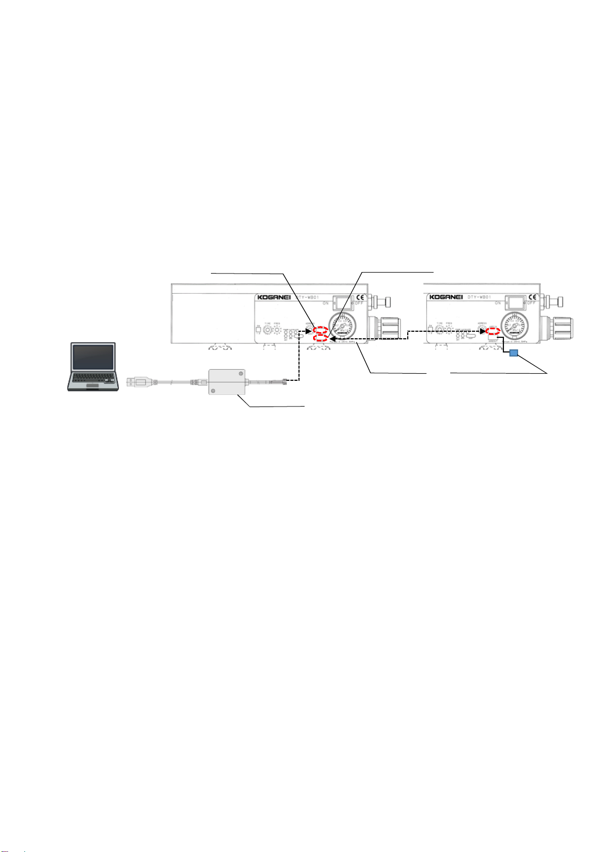
Instructions of Ionizer Air blow Type [DTY-ELK01] for appropriate handling and operation of this device.
Please keep this manual for your reference and consult it as needed.
1. Safety Precaution
Warning
This device is not for explosion-proof or water-proof. Do not install this device in a location where combustible
gases and/or solvents are used (in a coating booth, for example). Otherwise, there is a risk of ignition and/or
explosion.
When cleaning the discharge needle, always turn off the device. Also, the tip of the discharge needle is sharp, pay
attention when handling the discharge needle. Otherwise, there is a risk of injury.
This device uses the input air. When turning on this device, always input the air.
As high voltage is applied to the discharge needle equipped to the ionizer, do not move the fingers, body, and
metal pieces such as wires and tools close to the discharge needle. Otherwise, it can lead to an electric shock or
device failure. This device is a high voltage equipment. Do not install this device in a place exposed to water or oil,
high temperature, or high humidity. Especially, avoid a place with high humidity and a chance of dew
condensation.
The fluid used for the ionizer is the air. Do not use any other fluid.
Never disassemble, repair, or modify this device. Otherwise, it can lead to an accident or device failure.
Always turn off the device before performing the wiring, installation, and inspection tasks. Otherwise, it can lead to
an accident, electric shock, or device failure.
Do not point the nozzle tip to a person.
Wear the protective glasses and ear plugs to prevent scattering objects by the air blow from entering eyes and
noise induced deafness.
Install a shut-off valve on the supply side to ensure safety in case of a leak or breakdown.
Caution
Always ground the wire. Otherwise, it can lead to poor static charge removal characteristic or failure.
When this product is unusable or no longer necessary, the product should be disposed of as a piece of industrial
waste.
For the worker to be able to cut the power immediately, install a switch or a circuit breaker and label it properly.
Please wire properly. Incorrect or inappropriate wiring can cause a functional failure.
For the DC power source, use output voltage DC 24 V with double or reinforced insulation.
Due to the EN specification, wiring should be within 30 m.
This device has a high voltage generator. Do not cause abnormal discharge by moving a metal piece to the
discharge needle while current is applied. Otherwise, it can lead to failure or damages of peripherals or this
device.
The ionizer generates ozone in the air. Ventilate the room when the ozone odor is felt.
Do not move your face closer to the ion outlet to check the ozone odor. Otherwise, there is a risk to damage the
nose and throat.
This product cannot be used if the following substances are included in the fluid used :
Organic solvent, phosphate hydraulic operating fluid, sulfurous acid gas, chlorine gas, acids.
Do not use this device in a location exposed to direct sunlight (ultra-violet ray); with dust, salt, or iron powder; high
humidity; or atmosphere with organic solvent, phosphate hydraulic operating fluid, sulfurous acid gas, chlorine
gas, or acids. Otherwise, it can lead to loss of function in short period, rapid decrease in performance or shorter
life span.
The life of the discharge needle varies depending on the operating environment. A poor operating environment
(atmosphere with high humidity, for example) and/or unclean discharge needle can degrade the performance. A
periodical maintenance is required.
Please be advised that inrush current would be applied when turning on this product and when the built-in DC fan
in the dust collecting unit starts.
Air contaminated with oil and/or solid matters cannot be used. For the supplied fluid, use the cleaned air (use a
filter with a nominal filtration rating of 40 μm or less). Drain or dust entered inside the product can cause an
operational failure.
To prevent dew condensation and freeze due to the blow from the product, maintain a dew-point temperature of
the supplied fluid lower than the ambient atmosphere temperature using a refrigeration air dryer and/or an after
cooler.
Do not drop, step on, or hit the product. Otherwise, the product may be damaged.
Walls or objects near the exhaust slot of the dust collecting unit affects the exhaust ventilation. Please keep
enough spaces when installing the product.
For other warning and caution items, refer to the “Safety Precautions” in the general catalog.

- 27 -
2. Overview
ION WIPER Separate Type is an out-of-box static eliminator/particle removing apparatus to remove particles adhered on the workpiece
(charged material).
Ionized air coming out from the ionizer built into the blow unit neutralizes the static electricity on the charged material.
At the same time, the air blow from the blow nozzle blows out the particles on the material.
In addition, the dust collecting unit collects dusts and the filter catches the dust, exhausting from the rear of the project.
A unit type product for flexible installation to a device and a process and a box type product for installi ng on a workbench are available.
Verify that all the contents below are included in the package. If any item is missing, please contact your dealer (distributor) or a nearest
Koganei office.
[DTY-WB01]
Blow unit……x1 / L-shaped brackets and mounting (M4 x 0.5, length 6 mm) … 4 pieces each
[DTY-ZMW01]
Dust collecting unit…… x1 / L-shaped bracket … x4 *Four mounting screws (M4 x 0.5, length 6 mm) are fixed to the dust collecting
unit.
[DTY-WBM01-S/DTY-WBM01-L]
Box unit body…… x1 / Micro screw driver… x1 *Use the micro screw driver for operating the photoelectronic sensor switches.
21. System Configuration
[DTY-WB01]
Install the blow unit to a device to remove static charge/particles.
Connect the additional parts to the blow unit, as needed.
[DTY-WBM01]
The Box type product can be installed to a workbench to remove static charge/particles and collect particles.
Control circuit
(such as PLC)
PC
Photoelectronic
sensor:
DTY-ZSP□L-WB
Electrostatic potential
sensor:
DTY-EPS01-EA-□LWB
Dust collecting unit:
DTY-ZMW01-□-□
(Additional parts)
Blow unit:
DTY-WB01-□-□
DC power/AC adapter
Control circuit
(such as PLC)
PC
DC power/AC adapter
Nozzle:
DTY-NZW-□
Box type: DTY-WBM01-S/DTY-WBM01-L
Blow unit
Dust collecting unit
Photoelectronic sensor
Housing (aluminum frame)
Clear cover
(PET anti-electricity type)

- 28 -
3. Device Configuration and Features
The blow unit consists of various functional parts, including the ionizer (DTY-ELK01) and valves, as well as the electric/air control circuits
that operate these functional parts.
For collecting dusts, an additional part -- dust collecting unit (DTY-ZMW01) -- is available.
31. Terms and Functions of Each Part
[Blow unit: DTY-WB01-□-□]
[Dust collecting unit: DTY-ZMW01-□-□]
Unit Term Feature Reference Section
Blow unit Power connector Power 24 V/0 V/FG is connected. 4-2-1. Power and ground
connection
I/O connectors These connectors are used to connect PLC and other components to control
the blow unit.
4-2-2. Connecting to external
devices
Connectors for the dust
collecting units 1 & 2
These connectors are used to connect to the dust collecting units. 4-2-3. Connecting the dust
collecting unit
Connector for the
photoelectronic sensor
This connector is used to connect the photoelectronic sensor. 4-2-4. Connecting the
photoelectronic sensor
Connector for the
electrostatic potential
sensor
This connector is used to connect the electrostatic potential sensor. 4-2-5. Connecting the
electrostatic potential sensor
Communication This port is used to connect to an external device such as a PC, and to
retrieve various settings and information.
4-2-6. Connecting
communication devices
6. Communication
Air IN port This is a piping port for the air blow and ionized air. 4-3. Air Piping
Nozzle (ionized air outlet) This is the nozzle from which the ionized air (for static charge removal) is
blown out.
4-3. Air Piping
Nozzle (blow air outlet) This is the nozzle from which the blow air (for static charge removal) is blown
out.
4-3. Air Piping
Throttle valve for air blow This valve adjusts the flow rate of the blow air (for static charge removal). 5-1. Operation Procedures (2)
Ionized air regulator This component adjusts the impressed pressure of the ionizer. 5-1. Operation Procedures (2)
Pressure gauge (for ionized
air)
This component displays the pressure applied to the built-in ionizer.
(Configured on the ionized air regulator)
5-1. Operation Procedures (2)
Setting switches These switches are used to set the blow time/blow intermittent frequency. 5-1. Operation Procedures (3)
Power switch This switch is used to turn on/off the blow unit and the additional parts. 5-1. Operation Procedures (4)
LED indicators These indicators indicate the status of the blow unit and the additional parts. 5-2. LED Indicators
Dust
collecting
unit
Dust collecting cable This cable is connected to the blow unit. 4-2-3. Connecting the dust
collecting unit
Fan filter (IN) This is the filter on the suction side.
(This filter is designed to prevent foreign objects such as screws from entering
inside the product)
4-4. Exhaust Ventilation
Fan filter (OUT) This is the filter on the exhaust side. 4-4. Exhaust Ventilation
Pressure gauge (for ionized air)
Setting pressure range: 0.05 - 0.5 MPa
Setting switches
Power switch
Nozzle (ionized air outlet) Nozzle (blow air outlet)
Throttle valve for air blow
Ionized air regulator
*) set to a value within a
range of 0.05 -
0.5 MPa using
the pressure gauge (for
ionized air)
Connector for
the
electros tatic
potential sensor
Air IN port (φ8 quick joint)
Impressed pressure range:
0.2 - 0.7 MPa
Connector for the
photoelectronic
sensor
Connector for the dust
collecting unit 2
Connector for the dust
collecting unit 1
Dust collecting cable
Fan filter (OUT) Fan filter (IN)
Power connector
I/O connectors
LED indicators
Communication

- 29 -
4. Installation and Wiring/Piping
41. Installation Precaution
• This product should be used an indoor environment. When installing this product, pay attention to the pollution by water and oil,
high temperature, and high humidity.
• Especially, avoid a place where dew condensation is anticipated.
• Use the L-shaped bracket to securely fix the product. Do not install this product to an unstable place.
The fi xing screws for the L-shaped bracket are M4 x length 5 mm. When the screws are prepared at the customer site, use
screws of M4 x length 5 mm to 10 mm.
• Box type DTY-WBM01 should be installed on a robust and flat place like a workbench. Do not install this product to an unstable
place.
• For the blow unit side operation area/air piping (φ8 tube), keep a space larger than 100 mm when installing this product.
Also, for the exhaust from the dust collecting unit, keep a space larger than 100 mm when installi ng this product.
42. Wiring
4-2-1. Power and ground connection
Connect the power cable (DTY-ZDW-□) or the AC adapter (DTY-ZPS4) to the power connector POWER.
Connect the cable securely by inserting the cable until the lock lever locks on the power connector. To disconnect the cable push
down the lock lever fully and hold the connector and remove the cable. Do not apply excessi ve force to the lead wire.
Connect to the power (DC 24 V). The ground wire (green) of the power cable must be grounded.
(Connection using the power cable: DTY-ZDW-□)
Terminal No. Symbol Connecting cable color
1 NA White
2 0 V Black
3 24 VDC Red
4 FG Green
Connect the red power cable (terminal No.3) to the 24 V DC power.
Connect the black power cable (terminal No.2) to the 0 V power.
Ground the green power cable (terminal No.4).
Note: Connect the red and black power cables correctly.
As the reverse connection protective circuit is built-in, the product would not be damaged but does not operate correctly.
(Connection using the adapter: DTY-ZPS4)
Connect the AC adapter cable to the AC adapter, and connect to the AC outlet (100 VAC - 240 VAC, 50 Hz/60 Hz).
Ensure to ground the ground wire (green).
Note: Always ground the ground wire (green) to prevent static charge and to achieve full performance of the ionizer.
Incomplete grounding would degrade the discharge performance.
Note: 0 V and FG (ground terminal) are internally connected.
Power connector
Power cable: DTY-ZDW-□
AC adapter: DTY-ZPS4 AC adapter cable
Ground wire
To the AC outlet

- 30 -
4-2-2. Connecting to external devices
The following table shows the I/O connector specification. Refer to this table when connecting external devices such as PLC.
● Input specification
Item Specification
Input voltage DC 24 V ± 5% (Common to DC 24 V power)
Input current 4.8 mA at DC 24 V
Input response time ≥ 30 ms
Input impedance 4.7 kΩ
● Output specification
Item Specification
Output system Transistor output, NPN open collector
(with overcurrent protection)
Output voltage 24 V DC ± 5%
Output current 50 mA Max
Leakage current when the power is OFF 0.10 mA Max
Residual voltage when the power is ON 0.3 V Max at 5 mA; 1.0 V at 50 mA Max
Output response time ≥ 30 ms
[I/O connector terminal list]
Terminal No. Term I/O Description
1 ALARM Output Output abnormality (refer to "8. Troubleshooting" for details)
2 CHECK Output Ionizer discharge abnormality (1 shot pulse of 200 ms is output at abnormality)
3 MAINT Output Maintenance output (air valve for blow/ionizer discharge needle)
4 EPS Output Electrostatic potential sensor decision output (output when the output is below the setting
value)
5 DUST Output Dust sensor decision output (output when the output is below the setting value)
6 END Output Blow operation finish output (1 shot pulse of 200 ms is output when the operation finishes)
7 VAC_START Output External device operation output
8 STOP Input Operation stop input
9 START Input Operation start input
10
ZC
(Zero
calibration)
Input
Electrostatic potential sensor zero calibration input
This is a feature to calibrate the reference potential where the measured value equals to 0 V.
0 V potential is read while facing to the grounded metal plate or a space without charged
objects.
11 DC24 V -
Power DC 24 V output
It is connected to the 24 V power of, for example, an external sensor. (Capacity 24 V/100 m A
Max)
12 0V - I/O 0 V (common to the power connector 0 V)
Note: 0 V and FG (ground terminal) are internally connected.
Note: Value of the dust sensor is just a guide. It does not guarantee removal of dust from the workpiece.
Electrostatic
potential sensor
Main circuit
Main circuit
Main circuit
Main circuit
(Brown) 24V
(White) A(+)
(Blue) 0V
(Black) B(-)
(Brown) 24V
(Blue) 0V
(Black) SIG
(Brown) 24V
(White) A(+)
(Blue) B(-)
(Black) 0V
(Brown) 24V
(White) A(+)
(Blue) B(-)
(Black) 0V
Photoelectronic
sensor
Dust collecting
unit (1)
Dust collecting
unit (2)
Signal connector
DC
power/AC
adapter
DC 24 V output
Communication
connector (485 IN)
Communication
connector (485
Communication
cable
Communication
cable
(White) A(+)
(Pink) B(-)
(Yellow) GN D
Communication
device
(White) A(+)
(Pink) B(-)
(Yellow) GN D
Next unit
Load
Load
Load
Load
Load
Load
Load
Main circuit
External connection example
Internal circuit
PIN No.

- 31 -
4-2-3. Connecting the dust collecting unit
Connect the dust collecting unit connector CON3/CON4 when collecting dust using the dust collecting unit (DTY-ZMW01-□-□).
Up to two dust collecting units can be connected to a single blow unit.
(When the dust collecting units equipped with the dust sensors are connected to both of CON3 and CON4, the display and
output are based on the higher value of the dust sensors.
[Terminal array]
Terminal No. Symbol Connecting cable color
1 24 VDC Brown
2 A(+) White
3 B(-) Blue
4 0 V Black
5 NA(FG) -
4-2-4. Connecting the photoelectronic sensor
When the photoelectronic sensor (DTY-ZSP□L-WB) is used, connect it to the photoelectronic sensor connector CON2.
[Terminal array]
Terminal No. Symbol Connecting cable color
1 24 VDC Brown
2 NA -
3 0 V Blue
4 SIG Black
The photoelectronic sensor can be installed to the nozzle surface of the blow unit. Use the enclosed screws to mount the
sensor. (Either of 2 positions)
4-2-5. Connecting the electrostatic potential sensor
When the electrostatic potential sensor (DTY-EPS01-EA-□LWB) is used, connect it to the electrostatic potential sensor connector
CON1.
Remove the coat of the tip of the electrostatic potential sensor cable (6 mm removal is recommended), crimp a rod terminal and
connect to CON1.
Ground the round terminal of the cable. (Connect it to a L-shape bracket fixing screw.)
For the specification details/use method of the electrostatic potential sensor, refer to the operating instructions of [Electrostatic
potential sensor DTY-EPS01].
[Terminal array]
Terminal No. Symbol Connecting cable color
1 24VDC Brown
2 A(+) White
3 0V Blue
4 B(-) Black
Connector for dust collecting unit 1
CON3
Connector for dust collecting unit 2
CON4
Photoelectronic sensor:
DTY-ZSP□L-WB
Connector for the
electros tatic potential
sensor
CON2
Connector for the electros tatic potential sensor
CON1
Electrostatic potential sensor:
DTY-EPS01-EA-□LWB
Dust collecting unit: DTY-ZMW01-□-□
Connect to the
electrostatic
potential sensor
Connect to the blow unit
←
Ground
(Connect the round terminal)
Round terminal
Power connector 5-pin
Communication
connector 4-pin
Photoelectronic sensor installation positions
(M3 screw)
Electrostatic potential
sensor cable

- 32 -
Note: Connect the 24 VDC and 0 V to their correct connectors. Otherwise, the device does not function normally.
In addition, wrong wiring may cause operation failure and damage of the product. Always check wiring before turning on the device.
When connecting the electrostatic potential sensor: DTY-EPS01-EA-□LWB for the first time, connect the power connector only and
ensure that the green LED of the sensor body is correctly turned on. Then, turn off the device and connect the communication
connector.
If the device is turned on when the power of the electrostatic potential sensor has a reverse connection, the device may be
damaged.
Note: When inserting a cable to each screwless terminal connector, use a Phoenix contact's screw driver SZS 0,4X2,0 (size: 0.4 x 2.0 x
60 mm) or an equivalent product.
Note: Do not connect to the terminal symbol NA (FG) connectors. If different voltage is supplied, the product may be damaged,
Note: Measurement value may be affected if dust adheres to the dust passage hole of the dust sensor. If dust is adhered to the dust
passage hole, removed the fan filter on the OUT side and clean the hole section with air. Life span of the LED used in the dust
sensor is limited. Light output will weaken over time when turned on (by less than 5% per 5 years).
4-2-6. Connecting communication devices
When a communication device such as a PC is connected, connect a USB-RS458 converter (IBM2A-H1-□) to the
communication connector (485IN),
When a daisy-chain connection is used, connect a daisy-chain cable (DTY-EPP-CG-□) to the communication connector
(485OUT), and connect to the communication connector of the next blow unit (485IN).
Connect a terminating resistor connector (IBFL-K-TR) to the communication connector of the last blow unit (485OUT).
For details of communication, refer to "6. Communication".
Note: When connecting the communication cable for the first time, ensure that the Power (green) LED of the blow unit successfully
turns on and turn off the light before connecting the cable. If the device is turned on when the communication cable or USB-
RS485 converter is connected while the power has a reverse connection, the device may be damaged.
PC
Communication connector
(485OUT)
Communication connector
(485IN)
Dais y-chain cable
DTY-EPP-CG-□
USB-RS485 converter
IBM2A-H1-□
Next blow unit
Terminating resistor connector
IBFL-K-TR

- 33 -
43. Air piping
• Use a urethane or nylon tube of a φ8 outer dimension for the air piping.
• Use clean air through a dryer or filter for the air supply.
• Connecting the nozzle
Select a nozzle to attach to the blow unit according to the workpiece to remove static charge/particles.
Nozzle piping bore: Rc1/8
Do not use nozzles other than the following nozzles. Do not close the ionized air outlet with a plug, etc.
Recommended tightening torque:5 N・m
(For pinpoint removal of static charge/particles)
Nozzle: DTY-NZW-PP02 nozzle bore φ2.0 mm (It is dedicated particles removal nozzle)
DTY-NZW-PP03 nozzle bore φ3.0 mm
DTY-NZW-PP04 nozzle bore φ4.0 mm
(For removal of static charge/particles in a large area)
Nozzle: DTY-NZW-SW60 nozzle shower 60°
DTY-NZW-SW90 nozzle shower 90°
DTY-NZW-FT01 nozzle flat
To adjust the nozzle angle, use in conjunction with the nozzle joi nt: DTY-NZW- NJ01.
After adjusting the nozzle angle, lock it and use it.
Angle adjustable range of the nozzle joint: ±25°
Recommended tightening torque: Body 1 N・m / Nozzle 0.3 N・m
44. Exhaust Ventilation
• Dust collecting unit (DTY-ZMW01-□-□) has a dust collection filter in it.
There is a fan inside the unit. Be careful about an injury due to the fan and the fan damage.
The fi lter on the fan filter (OUT) side collects particles.
(The filter on the fan filter (IN) side is a filter to prevent larger particles from entering inside the dust collecting unit.)
The fi lters are consumables. Replace the filter (DTY-ZFF-WB/ DTY-ZFR-WB) when the filter is clogged or contaminated.
• The exhaust duct outer diameter is φ76.3 if the dust collecting unit is not used but the duct attaching bracket (DTY-ZBRB-WB)
(additional part) is used,
When connecting exhaust hose, pay attention to the exhaust resistance. (Recommended exhaust hose nominal diameter: φ75)
Air piping joint
Air IN port
Fan fi lter (OUT)
Fan fi lter (IN)
Inhalation irection
Exhaust direction
Filter
IN side: DTY-ZFF-WB
OUT side: DTY-ZFR-WB
Nozzle (blow air outlet)
[Front] [Side]
Nozzle (ionized air outlet)
Nozzle joint: DTY-NZW-NJ01
Note:Prepare sufficientain supply to minimize the pressure drop during operation

- 34 -
5. Operation
51. Operation procedures
(1) Ensure the power connection, grounding, air piping, wiring, and exhaust ventilation (dust collecting unit/duct piping).
(Working pressure range: 0.2 - 0.7 MPa)
(2) Open the valve source of the air device (installed by the customer) and adjust the throttle valve for the ionized air regulator/air
blow.
Adjust the ionizer supply air pressure to be withi n a range of 0.05 - 0.5 MPa. When turning on this device, always input the
air.
(Ionized air regulator)
Rotate the regulator handle with the handle securely pulled out. Rotate clockwise to increase the pressure, and rotate counter-
clockwise to decrease the pressure.
After the adjustment completes, push the handle to lock it.
Check the pressure with the pressure gauge at the front of the blow unit. (Setting range: 0.05 - 0.5 MPa)
(Throttle valve for air blow)
Rotate the throttle valve needle from the fully open position to the counter-clockwise direction to increase the blow flow rate.
When the desired flow rate is achieved, always fasten the locknut to secure the setting.
When the needle is rotated too much (the flow rate is too high), rotate the handle clockwise to decrease the flow rate.
(3) Set the blow time and blow intermittent frequency using the blow time switch TIME/blow intermittent frequency switch FREQ.
For the blow time, either use the timer setting (0.5 - 10.0 seconds) or select the blow time switch No. from the continuous setting.
When the timer setting is used (blow time setting switch No.0 - A), the product blows the air for the configured time.
When the continuous setting is used (blow time setting switch No. B - F), the product blows the air when the photoelectronic sensor
detects the workpiece.
For the continuous setting, the sensor OFF delay time can also be selected. When removi ng particles manually, for example, the
products keeps blowing the air during the OFF delay time if the target workpiece is out of the range of the photoelectronic sensor. If
the workpiece is detected again during the OFF delay time, the OFF delay time is reset.
When the blow intermittent frequency setting is used, the product provides intermittent blow at the frequency specified by the blow
intermittent frequency switch No.
Set the switch No. to "0" to disable intermittent blow.
The blow intermittent frequency switch No.8/No.9 are the user area that allows the customer to set desired behaviors.
There are two areas. The blow time/intermittent frequency/operation interval time can be configured according to the user
environment.
For details, refer to Section 6-3-4. (Setting via communication is required.)
Note: The intermittent operation is available for air blow only. Intermittent blow is not available for the ionized air.
Ionized air regulator
Throttle valve for air blow
Needle
Locknut
Handle < 0.5 MPa
> 0.05 MPa
Blow time switch
TIME
Blow intermittent frequency switch
FREQ
(Blow time switch) (Blow i ntermittent frequency switch)
Blow time switch Blow ti me Remark
No. [second]
0 0.5 -
1 1.0 -
2 2.0 -
3 3.0 -
4 4.0 -
5 5.0 -
6 6.0 -
7 7.0 -
8 8.0 -
9 9.0 -
A 10.0 -
B Continue S ens o r OFF_de lay tim e 0.1 second
C Continue S ens o r OFF_de lay tim e 0.5 second
D Continue S ens o r OFF_de lay tim e 1.0 second
E Continue Se nso r OFF_d ela y time 2.0 s eco nds
F Continue Se nso r OFF_d ela y time 3.0 s eco nds
Blow in termi ttent
frequency s witch No .
Bl ow frequency
[Hz]
Re mark
0 0 No intermitte nt
operation
1 1 -
2 2 -
3 3 -
4 4 -
5 6 -
6 8 -
7 10 -
8 User area 1 -
9 User area 2 -
Increase
pressure
Decrease
pressure
Unlock
Lock

- 35 -
ON
OFF
ON
OFF
ON
OFF
ON
OFF
ON
OFF
ON
OFF
ON
OFF
T1
T3 T5
T4
T7
T1
T8
T2 T6
[Time chart]
• When the blow time is specified (blow time setting switch No.0 - A)
Photoelectronic sensor or
external input [START]
External output
[VAC_S]
External output [END]
External input [STOP]
Dust collecting unit
(DC fan)
Ionized air
Air blow
Symbol Term Time [ms] Remark
T1 Input signal ON delay time 100
Operation starts when the photoelectronic sensor or external input
[START] is greater than T1
T2
Dust collecting operation time prior to blow
200
Dust collecting operation time prior to air blow
T3
Ionized air time prior to blow
100
Ionized air time prior to air blow
T4 Air blow time
Set by the blow time
setting switch Air blow time
T5
Ionized air time after blow
0
Ionized air blow time after air blow
T6
Dust collecting operation time after blow
200
Dust collecting operation time after air blow
T7
External output [END] time
200
External output time (1 shot pulse)
T8 Input signal OFF delay time 100
The subsequent operation is accepted when the photoelectronic
sensor or external input [START] is greater than T8
• Continuous blow is specified (Setting switch No. B - F)
Photoelectronic sensor or
external input [START]
External output
[VAC_S]
External output [END]
External input [STOP]
Dust collecting unit
(DC fan)
Ionized air
Air blow
Symbol Term Time [ms] Re mark
T1 Input signal ON delay time 100
Operation starts w hen the photoelectronic sensor or external input
[START] is greater than T1
T2
Dust collecting operation time pr ior to blow
200
Dust collecting operation time prior to air blow
T3
Ionized air time prior to blow
100
Ionized air time prior to air blow
T4 Air blow time
Photoelectronic sensor or external input [START]
When ON (excluding T2/T3, including T8) Air blow time
T5
Ionized air time after blow
0
Ionized air blow time after air blow
T6
Dust collecting operation time after blow
200
Dust collecting operation time after air blow
T7
External output [END] time
200
External output time (1 shot pulse)
T8 Input signal OFF delay time Set by the blow time setting sw itch
Air blow operation stops w hen the setting is greater than T8 (OFF)
The operation continues w hen the photoelectronic sensor or the
external input [START] is OFF once and back to ON again w ithin T8.
Note: When the external input [STOP] is set to ON, the photoelectronic sensor/external input [START] is not accepted.
To enable the operation again, set the external input [STOP] and the photoelectronic sensor/external input [START] to OFF, and
then activate the operation.
Set by the blow intermittent frequency switch No.
ON
OFF
ON
OFF
ON
OFF
ON
OFF
ON
OFF
ON
OFF
ON
OFF
T4
T3
T5
T1 T1
T2 T6
T7
T8
Set by the blow intermittent frequency switch No.

- 36 -
• At the external input [STOP]
Photoelectronic sensor or
external input [START]
External output
[VAC_S]
External output [END]
External input [STOP]
Dust collecting unit
(DC fan)
Ionized air
Air blow
(4) Press the "-" side of the power switch to turn on the device. The device turns on. If the power LED (green) and the
photoelectronic sensor are equipped, ensure that the power LED (green) of the photoelectronic sensor is turned on before
entering the workpiece.
The photoelectronic sensor detects the entered workpiece and the device starts the operation.
(5) The blow operation is performed with the blow time/blow intermittent frequency set in Step (3), and then the operation stops.
This is the end of the static charge/particle removal process.
Note: When adjusting the nozzle angle using the nozzle joint, if the air flow nozzle is directed to the ionized air nozzle, the static charge
removal performance may be affected.
Use the product with the air blow nozzle facing the vertical direction or the opposite direction of the ionized air nozzle.
Static charge removal performance may be affected if the ionized air pressure (set value of the ionized air regulator) is low
compared to the air blow pressure (impressed pressure).
(Recommended nozzle direction)
[Air blow nozzle vertical direction] [Air blow nozzle opposite direction]
Power switch
Ionized air nozzle
Air blow nozzle
Target workpiece Target workpiece
Ionized air nozzle
Air blow nozzle
Static charge
removal Particle removal
Dust
collection
Dust collecting unit, etc.
Static charge
removal Particle removal
Power LED (green)
ON
OFF
ON
OFF
OFF
ON
OFF
ON
OFF
ON
OFF
ON
OFF
T3
T1 T1
T2
Set by the blow intermittent frequency switch No.

- 37 -
52. LED Indicators
These indicators (turned on/flash/turned off) indicate the status of the blow unit and the additional parts.
For the details, refer to the LED status table.
(LED status table)
*1) To enable maintenance, enable the piano dip switch SW1/2 on the front of the blow unit.
(Refer to "7. Maintenance and Precautions" for details)
(Initial value) Ionizer discharge time: 300 [time]/frequency of air blow valve ON/OFF: 10 million times
Note: While the ion wiper is in operation, ensure that air is supplied to the equipped ionizer.
If the pressure setting of the ionized air regulator is less than 0.05 MPa, the device and the environment would receive harmful
effect.
Note: The particle removal effect by the ion wiper varies depending on the shape and the amount of charge of the workpiece (charged
material), air pressure, blow time, and blow intermittent frequency.
When this device is used, configure the ionized air pressure, blow flow rate/time/frequency appropriate to the workpiece.
Note: Value of the dust sensor is just a guide. It does not guarantee removal of dust from the workpiece.
Power LED POWER (green)
Alarm LED ALM (red)
Maintenance LED MAINT (yellow)
Ion blow LED ION BLOW (blue)
Electrostatic potential sensor LED EPS (yellow)
Dust sensor LED DUST (Blue/green/red)
LED
Item POWER
(green)
ALM
(red)
MAINT
(yellow)
ION BLOW
(blue)
EPS
(yellow)
DUST
(red/green/
blue)
○○○○○○
◎○○○○○
●-----
●--●--
Maintenance*1) Ionizer discharge needle ● - ◎
(2Hz) ---
Air blow valve ● - ◎
(4Hz) ---
Ionizer discharge needle/
Air blow valves (both) ●-●---
Alarm Ionizer ●●----
Blow unit ●◎
(4Hz) ----
Dust collecting unit: ●◎
(2Hz) ----
Electrostatic potential
sensor ●◎
(1Hz) ----
Electrostatic
potential sensor Judgment output ON ●---●-
Zero-point calibration
execution ●---◎
(2s,2Hz) -
Outside the measurement
range ●---◎
(4Hz) -
Dust sensor Dust amount: little ●----●(Blue)
Dust amount: medium ●----●(Green)
Dust amount: high ●----●(Red)
Dust sensor not equipped ●----○
●: On ◎: Flash ○: Off
Power OFF
Power ON
Blowing the ionized air
While starting up from the power ON

- 38 -
6. Communication
61. Address Setting
To communicate with the blow unit, it is necessary to configure the unit address for each blow unit.
Use the address setting switch to set the address. Up to 15 units can be connected in a daisy-chain.
Ensure that there are no duplicated addresses. Duplicated addresses prevent correct communication.
Also, do not set the address switch No. to "0". This setting disables communication.
62. Communication Specification
(Communication settings specification)
Item Description
Communication protocol Modbus-RTU
Physical layer RS-485
Communication method Half duplex, start-stop
Maximum number of
connected units 15 Max
Address Setting 1-F[15] (use the rotary switch on the front body)
Communication is disabled when set to 0.
Communication speed 115.2 kbps
Data bit 8 bit
Start bit 1 bit
Stop bit 1 bit
Parity Odd number
Flow control None
(Communication frame configuration)
Start Address
(1-15)
Function code
(1-6) Data Error check
CRC End
Silent interval with 3.5
characters (350 s) or more 1 byte 1 byte n byte 2 byte Silent interval with 3.5
characters (350 us) or more
(Corresponding function code)
Function code Function term Description
1 Read Coil Status DO state (0/1) read
2 Read Input Status DI state (0/1) read
3 Read Holding Register Retention register read
4 Read Input Register Input register read
5 Force Single Coil DO state (0/1) overwrite
6 Preset Single Register Retention register overwrite
63. Communication Data Address
Use the data address when reading or modifying (writing) data in Modbus communication.
6-3-1. Read Coil Status (function code: 1)/ Force Single Coil (function code: 5)
Read by the function code 1, and overwrite by the function code 5.
(Readable and overwritable binary data, such as ON/OFF, is deployed)
Data address Term Description
0 Stop
Operation stop (equivalent to I/O connector terminal No.8: STOP)
Operation stops when toggled to 0 -> 1
* The operation status is reset before starting the operation.
1 Start Operation start signal (equivalent to I/O connector terminal No.9: START)
Operation starts when toggled to 0 -> 1
2 ZC
Electrostatic potential sensor zero calibration execution (equivalent to I/O connector
terminal No.10: ZC)
Calibration is executed when toggled to 0 -> 1
* Automatically cleared to 0 when the execution successfully completes. If zero
calibration does not complete after 100 ms, the process is not complete
successfully. Check the connection state and the electric potential, etc.
Address setting switch
ADDRESS
ADDRESS Address Remark
Switc h No.
0 0 Do not configure
1 1 -
2 2 -
3 3 -
4 4 -
5 5 -
6 6 -
7 7 -
8 8 -
9 9 -
A 10 -
B 11 -
C 12 -
D 13 -
E 14 -
F 15 -

- 39 -
6-3-2. Read Input Status (function code: 2)
Read by the function code 2.
(Readable binary data, such as ON/OFF, is deployed)
Data address Term Description
0 ALARM This indicates the same state as the I/O connector terminal No.1: ALARM.
0: OFF, 1: ON
1 CHECK This indicates the same state as the I/O connector terminal No.2: CHECK.
0: OFF, 1: ON
2 MAINT This indicates the same state as the I/O connector terminal No.3: MAINT.
0: OFF, 1: ON
3 EPS This indicates the same state as the I/O connector terminal No.4: EPS.
0: OFF, 1: ON
4 DUST This indicates the same state as the I/O connector terminal No.5: DUST.
0: OFF, 1: ON
5 END This indicates the same state as the I/O connector terminal No.6: END.
0: OFF, 1: ON
6 VAC_START
This indicates the same state as the I/O connector terminal No.7:
VAC_START.
0: OFF, 1: ON
7 STOP This indicates the same state as the I/O connector terminal No.8: STOP.
0: OFF, 1: ON
8 START This indicates the same state as the I/O connector terminal No.9: START.
0:OFF, 1:ON
9ZC
(Zero calibration)
This indicates the same state as the I/O connector terminal No.10: ZC.
0:OFF, 1:ON
10 Touch Sensor This indicates the detection state of the photoelectronic sensor.
0:OFF, 1:ON
11 EPS Connect Connection state of the electrostatic potential sensor.
0: not connected, 1: connected
12 DUST1 Connect
Connection state of the dust collecting unit 1
0: not connected, 1: connected
* Dust collecting unit connected to the dust collecting unit 1 connector
CON3
13 DUST2 Connect
Connection state of the dust collecting unit 2
0: not connected, 1: connected
* Dust collecting unit connected to the dust collecting unit 2 connector
CON4
14 DUST1 FAN Error Fun error state of the dust collecting unit 1
0: normal, 1: error
15 DUST2 FAN Error Fun error state of the dust collecting unit 2
0: normal, 1: error
16 ELK CHECK CHECK state of the ionizer (DTY-ELK01)
0: OFF, 1: ON
17 ELK ALARM ALARM state of the ionizer (DTY-ELK01)
0: OFF, 1: ON
18 ELK HV Discharge state of the ionizer (DTY-ELK01)
0: OFF, 1: ON
19 ELK Maint Maintenance signal of the ionizer (DTY-ELK01)
0: OFF, 1: ON
20 Blow Valve Maint Maintenance signal for blow valve
0: OFF, 1: ON
24 Current Over ALARM Overcurrent error state of the I/O connector terminal No.1: ALARM
0: normal, 1: overcurrent error
25 Current Over CHECK Overcurrent error state of the I/O connector terminal No.2: CHECK
0: normal, 1: overcurrent error
26 Current Over MAINT Overcurrent error state of the I/O connector terminal No.3: MAINT
0: normal, 1: overcurrent error
27 Current Over EPS Overcurrent error state of the I/O connector terminal No.4: EPS
0: normal, 1: overcurrent error
28 Current Over DUST Overcurrent error state of the I/O connector terminal No.5: DUST
0: normal, 1: overcurrent error
29 Current Over END Overcurrent error state of the I/O connector terminal No.6: END
0: normal, 1: overcurrent error
30 Current Over START Overcurrent error state of the I/O connector terminal No.7: START
0: normal, 1: overcurrent error

- 40 -
6-3-3. Read Input Register (function code: 4)
Read by the function code 4.
(Read-only 16-bit data is deployed)
Data address Term Description Unit
0 EPS Data
Electrostatic potential sensor measurement electric potential
value (-20000 - 20000)
30000: + over range, -30000: - over range
The data is a 16-bit signed integer.
In the standard mode: -2000 - 2000, resolution 1
In the high voltage mode: -20000 - 20000, resolution 10
V
8 DUST1 Sensor
Dust collecting unit 1 dust sensor measurement value (0 - 1000)
If the value immediately after turning the power on is -1000 and
a dust sensor is used, the value of -1000 continues to be used.
Disconnected: -1
9 DUST1 Fan1 SP Dust collecting unit 1 fan 1 rotation speed (2500 to 8250)
Disconnected: -1000, On error: -1 rpm
10 DUST1 Fan2 SP Dust collecting unit 1 fan 2 rotation speed (2500 to 8250)
Disconnected: -1000, On error: -1 rpm
11 DUST2 Sensor
Dust collecting unit 2 dust sensor measurement value (0 - 1000)
If the value immediately after turning the power on is -1000 and
a dust sensor is used, the value of -1000 continues to be used.
Disconnected: -1
12 DUST2 Fan1 SP Dust collecting unit 2 fan 1 rotation speed (2500 to 8250)
Disconnected: -1000, On error: -1 rpm
13 DUST2 Fan2 SP Dust collecting unit 2 fan 2 rotation speed (2500 to 8250)
Disconnected: -1000, On error: -1 rpm
24 RSW Addr Current value of the ADDRESS switch (0 - 15)
25 RSW Freq Current value of the FREQ switch (0 - 9)
26 RSW Blow Current value of the TIME switch blow time (0 - 15)
27 PIANO SW Current values of the SW 1/2 switches (0 - 3)
40 BLOW Unit Major Ver Main unit major version
41 BLOW Unit Minor Ver Main unit minor version
42 EPS Major Ver Electrostatic potential sensor major version
43 EPS Minor Ver Electrostatic potential sensor minor version
44 DUSTUnit1 Major Ver Dust collecting unit 1 major version
45 DUSTUnit1 Minor Ver Dust collecting unit 1 minor version
46 DUSTUnit2 Major Ver Dust collecting unit 2 major version
47 DUSTUnit2 Minor Ver Dust collecting unit 2 minor version
50 Error History1 Error history 1 (clear not allowed, retention) [New]
51 Error History2 Error history 2 (clear not allowed, retention) ↑
52 Error History3 Error history 3 (clear not allowed, retention) |
53 Error History4 Error history 4 (clear not allowed, retention) |
54 Error Histor5 Error history 5 (clear not allowed, retention) |
55 Error Histor6 Error history 6 (clear not allowed, retention) |
56 Error History7 Error history 7 (clear not allowed, retention) |
57 Error History8 Error history 8 (clear not allowed, retention) |
58 Error History9 Error history 9 (clear not allowed, retention) ↓
59 Error History10 Error history 10 (clear not allowed, retention) [Old]

- 41 -
6-3-4. Read Holding Register (function code: 3)/ Preset Single Register (function code: 6)
Read by the function code 3, and overwrite by the function code 6.
(Readable and overwritable 16-bit data is deployed. The value of the retention register is maintained after the main unit is
turned off.)
Data
address Term Description Initial
value
Maximum
value
Minimum
value Unit
0 EPS Work size Workpiece size setting for the electrostatic potential sensor 300 400 20 mm
1 EPS Distance Measurement distance setting for the electrostatic potential
sensor 50 100 6 mm
2 EPS CP Thers Threshold setting for the electrostatic potential sensor
* "EPS CP Thers > EPS CP Hys" must be satisfied. 100 20000 0 V
3 EPS CP Hys Hysteresis setting for the electrostatic potential sensor
* "EPS CP Thers > EPS CP Hys" must be satisfied. 10 1000 0 V
4 EPS Mode Mode setting for the electrostatic potential sensor
0: standard mode, 1: high voltage mode 0 1 0
8 FAN1 SPEED Fan rotation speed setting for Dust collecting unit 1 8250 8250 2500 rpm
9 FAN2 SPEED Fan rotation speed setting for Dust collecting unit 2 8250 8250 2500 rpm
10 FAN1 Mode Operation mode setting for Fan 1
0: normal, 1: continuous (not turned OFF after the operation) 0 1 0
11 FAN2 Mode Operation mode setting for Fan 2
0: normal, 1: continuous (not turned OFF after the operation) 0 1 0
16 DUST Thres Dust sensor DUST signal threshold
* "DUST Thres >DUST Hys" must be satisfied. 50 1000 0 -
17 DUST Hys Dust sensor DUST signal hysteresis
* "DUST Thres >DUST Hys" must be satisfied. 10 100 0 -
18 DUST Led DH
Dust sensor LED threshold DH
Detected value >= DH: red LED turned on
DH > Detected value > DL: green LED turned on
Detected value <= DL: blue LED turned on
200 1000 0 -
19 DUST Led DL
Dust sensor LED threshold DL
Detected value >= DH: red LED turned on
DH > Detected value > DL: green LED turned on
Detected value <= DL: blue LED turned on
50 1000 0 -
21 End Count H Operation completion count upper 0 30000 0 x10,000
times
22 End Count L Operation completion count lower 0 9999 0 time(s)
23 ELK Clean H Ionizer discharge time (hour)
Automatic count at discharge 0 30000 0 h
24 EKL Clean S
Ionizer discharge time (second)
Automatic count at discharge
* Ensure to clear to 0 after a maintenance task completes.
0 3599 0 s
25 ELK Clean
Thres
Discharge needle maintenance time setting
(for MAINT output) 300 30000 0 h
26 Blow Valve
CntH Blow valve actuating cycle upper 0 10000 x10,000
times
27 Blow Valve
CntL
Blow valve actuating cycle lower
* Ensure to clear to 0 after a maintenance task completes. 0 9999 0 time(s)
28 Blow Valve Cnt
Thres Blow valve replacement (for MAINT output) 1000 10000 0 x10,000
times
32 UA1 ON Delay User area 1 ON delay time: T1 100 3000 0 ms
33 UA1 ON FAN User area 1 pre-blow blow time: T2 200 3000 0 ms
34 UA1 ON ELK User area 1 pre-blow discharge time: T3 100 3000 0 ms
35 UA1 Blow Time User area 1 blow time: T4 1000 60000 500 ms
36 UA1 OFF ELK User area 1 post-blow discharge time: T5 0 3000 0 ms
37 UA1 OFF FAN User area 1 post-blow blow time: T6 200 3000 0 ms
38 UA1 OFF
Delay User area 1 OFF delay time: T8 100 3000 0 ms
39 UA1 Blow Freq User area 1 blow frequency
0: continuous, 10 - 100: pulse blow 0 100 0 x0.1 Hz
40 UA1 Mode User area 1 operation mode
0: blow time specifying mode, 1: continuous mode 0 1 0
48 UA2 ON Delay User area 2 ON delay time: T1 100 3000 0 ms
49 UA2 ON FAN User area 2 pre-blow blow time: T2 200 3000 0 ms
50 UA2 ON ELK User area 2 pre-blow discharge time: T3 100 3000 0 ms
51 UA2 Blow Time User area 2 blow time: T4 1000 60000 500 ms
52 UA2 OFF ELK User area 2 post-blow discharge time: T5 0 3000 0 ms
53 UA2 OFF FAN User area 2 post-blow blow time: T6 200 3000 0 ms
54 UA2 OFF
Delay User area 2 OFF delay time: T8 100 3000 0 ms
55 UA2 Blow Freq User area 2 blow frequency
0: continuous, 10 - 100: pulse blow 0 100 0 x0.1 Hz
56 UA2 Mode User area 2 operation mode
0: blow time specifying mode, 1: continuous mode 0 1 0
*) Data addresses 32 - 40 and data addresses 48 - 56 are enabled when the blow intermittent frequency switch [FREQ]No.8 and the
glow intermittent frequency switch [FREQ]No.9 are set, respectively. For their behavior, refer to the [time chart] on page 11.

- 42 -
7.Maintenance and Caution Items
• While this device is installed to a place where no water or oil splashes over, if water, oil, paint, or other fluids splashes over the
device, wipe it out using a piece of cloth.
• Dirt contamination on the tip of the discharge needle of the equipped ionizer degrades the static charge removal performance.
If gradual degradation of the static charge removal effect is experienced, clean the tip of the discharge needle using an appropriate
tool such as a nylon brush. (Never use a wire brush.)
Clean the discharge needle and the area nearby using a swab.
When cleaning the discharge needle of the ionizer, remove the cover from the blow unit body.
For additional maintenance and precautions regarding the ionizer, refer to the operating instructions of DTY-ELK01.
• The blow intermittent operation of this ion wiper is controlled by an electromagnetic valve. The electromagnetic value has a product life.
The electromagnetic value is a consumable item. When it reaches the end of the product life, replace it. Model: 230E1-SR-26W DC24V
10 million ON/OFF cycles are considered as a milestone for replacement.
When replacing the electromagnetic valve , remove the cover from the blow unit body.
The electromagnetic valve is fixed with two screws.
Remove the screws and remove the electromagnetic valve from the blow unit body. Tilt the electromagnetic valve for easier
removal.
Disconnect the cables (red/black) from the electromagnetic valve connectors. Push down the white protrusion at the
electromagnetic valve connector and pull out the cable to disconnect the cable.
Align a new electromagnetic valve to the board silk and connect the cables (red/black) of the new electromagnetic valve.
Insert the cables while pressing down the white protrusion.
Ensure to set the electromagnetic valve O-rings (x3) to the specified locations.
After connecting the cable and attaching the O-rings, fix the electromagnetic valve with the screws. Recommended tightening torque: 0.5 [N・
m]
• Setting the maintenance time/count
The blow unit measures the discharge time of the ionizer. When the discharge time reaches the specified discharge time, the
maintenance LED MAINT (yellow) flashes (2 Hz) and I/O connector terminal No.3: MAINT is output.
The ON/OFF cycle of the air blow valve is also counted. When the number of cycle reach the specified count, the maintenance
LED MAINT (yellow) flashes (4 Hz) and I/O connector terminal No.3: MAINT is output.
When the flash/I/O connector terminal No.3: MAINT is acknowledged, replace the relevant parts.
To enable the count, SW1 or SW2 on the blow unit front must be set to ON. (They are set to OFF at the time of shipping)
Warning: Ensure to turn off the power before performing the inspection, cleaning, or maintenance task. Also, shut the connection to the
air completely.
When cleaning the discharge needle, pay attention to handle the needle as the tip of the discharge needle is sharp.
Otherwise, there is a risk of injury.
ON: Count enabled
OFF: Count disabled
OFF => ON: Count starts
ON => OFF: Count reset
Ionizer discharge time
Count switch SW1
Blow valve ON/OFF
Count switch SW2
Blow unit upper side
Blow unit rear side
Ionizer (DTY-ELK01) Discharge needle
Blow unit cover
Electromagnetic valve
(230E1-SR-26W
DC24 V)
Tilt the valve and remove it
O-ring mounting position (x3)
Enlarge
White protrusion
Cable slot
Fixing screw (x2)
Screw locations x2
Screw location x1
Red
B
la
ck

- 43 -
8. Troubleshooting
81. When a Problem Occurs
When contacting us for a problem, please inform us about the following items as specific as possible:
Item Description (example)
What Model (blow unit: DTY-WB01/Box type DTY-WBM01-S/-L)
Others
When Purchase date (serial No.)
Period of service, operating condition
When the power is on; One hour after the power is on
In what situation During operation
During configuration
What happened The unit does not function
An error occurs
Frequency Always occurs
Once in an hour
The problem is not reproduced
82. When Alarms Are Issued and Their Resolution
When the I/O connector ALARM signal output is ON, it is considered that an alarm is issued.
Also, the blow unit ALM (red) LED turns on/flashes. (For the details, refer to "5-2. LED Indicators".)
When an alarm is issued, refer to the solutions in "8-3. Alarm List".
83. Alarm List
Alarm
Code Alarm Subj ect Description B ehavior Possible Cause Resolution
1001 I/O connector terminal No.1 ALARM overcurrent Stop
1002 I/O connector terminal No.2 CHECK overcurrent Stop
1003 I/O connector terminal No.3 MAINT overcurrent Stop
1004 I/O connector terminal No.4 EPS overcurrent Stop
1005 I/O connector terminal No.5 DUST overcurrent Stop
1006 I/O connector terminal No.6 END overcurrent Stop
1007 I/O connect or terminal No.7 VAC STA RT
overcurrent
Stop
1020 Memory failure Stop
1030 Communication error (CRC mismatc h occurred) Continue
1031 Communication error (exception response
oc curred) Continue
2010 Dust collecting unit 1
2020 Dust collecting unit 2
3010 Zero calibration error Continue
・ Zero calibrat ion was performed within the range (within
±200 V)
(±2000 V in the high voltage mode)
P erform c alibration within the range (within ±200 V)
(± 2000 V in the high voltage mode)
3020 E lectrostatic potential sens or Stop The sens or is brok en Remove the sens or from the unit and attach it again.
If t he problem persists, contact us.
4010 Feature failure Stop The piezoelectric trans former is broken.
4020 Discharge failure Continue A bnormal discharge occurred
Electrostatic
potential s ensor
Ionizer
S hut the power, and check for any issues on the
dis c harge needle, such as contamination with dust.
If t he problem persists, contact us.
Blow unit
・ The load connected to the I/O output got short
circuited.
・ DC 24 V is applied without the load.
S hut the power, and check the load.
A fter removing the cause of the alarm, turn on the device.
・ Error in the communication settings
・ The power was turned ON while c ommunicating with
support soft ware
・ Effect by the noise
Check the communication settings.
Connect before applying the power.
Internal DC fan failure Stop
・ A foreign objec t stuck in the DC fan stopped the
rotation of the fan.
・ DC fan is broken.
Turn off the power, and remove the foreign object from the
DC fan, if any.
If t he problem persists, contact us.

- 44 -
9. Specification/External Dimension
91. Specification
Item
Type
Blow unit: DTY-WB01-□-□
Dust collecting unit: DTY-ZMW01-□-□
Input voltage 24 VDC±5%
Current consumption Blow unit: 0.6 A Max
Dust collecting unit x1: 1.0 A Max (2.0 A Max at start-up)
Equipped ionizer DTY-ELK01 (x1)
Ion balance *1) ±15 V (0.5 MPa, 50 mm)
Discharge time *1) 1 sec (1000 V → 100 V, 0.5 MPa, 50 mm)
Fluid used Air (Clean air free from water and oil)
Working pressure range 0.2 to 0.7 MPa
Ionized air setting pressure range 0.05 to 0.5 MPa
Piping connection bore φ8 quick joint
Air blow time Rotary switch TIME 16-
point
0.5 - 10 s/continuous (sensor OFF_delay: 0.1 s - 3.0 s)
Blow intermittent frequency Rotary switch FREQ 10-
point
1, 2, 3, 4, 6, 8, 10 Hz/continuous (no intermittent)
User setting 2 area
Switches Locker switch Power ON/OFF (○: OFF / -: ON)
Piano dip switch: SW1 Ionizer discharge time count enabled/disabled
(ON: count enabled/OFF: count disabled)
Piano dip switch: SW2 Blow valve ON/OFF cycle count enabled/disabled
(ON: count enabled/OFF: count disabled)
Indicators POWER (green, turns on when the power is on)
ALM (red, turns on/flashes on error)
MAINT (yellow, turns on when a maintenance required)
ION BLOW (blue, turns on during blow operation)
EPS (yellow, turns on at electrostatic potential sensor judgment)
DUST (blue/green/ red, indicating the dust sensor status)
External output Output ALARM (Output on error)
CHECK (Ionizer discharge abnormal output)
MAINT (Maintenance timing output)
EPS (Electrostatic potential sensor judgment output)
DUST (Dust sensor judgment output)
END (Blow operation end output)
VAC START (External device operation output)
Input STOP (Operation stop input)
Start (Operation start input)
ZC (Electrostatic potential sensor zero calibration input)
Connectability sensor Photoelectronic sensor: DTY-ZSP□L-WB
Electrostatic potential sensor: DTY-EPS01-EA-□LWB
Dust sensor
(Dust collecting unit: built into DTY-ZMW01-□-DS)
Nozzle Shower type: 60°, 90°, flat (three types)
Pinpoint type: φ2, φ3, φ4 (three types)
Consumed air flow rate *2) Air blow side 330 L/min (ANR)
Ionized air side 170 L/min (ANR)
Dust collecting fan exhaust flow rate 2000 L/min at no load
Filter collection capability *3) OUT side 62%
Communication RS485 communication
Number of communication connections 15
Operating environment Indoor 0 - 40°C, 15 -65% RH (no condensation)
Weight Blow unit: 2.1 kg (no photoelectronic sensor/power unit)
Dust collecting unit: 1.3 kg (with a dust sensor)
Mount 4 L-shaped brackets (screws) enclosed with each unit
Box type A4 type DTY-WBM01-S-□-□
Weight: 7.5 Kg
(with a nozzle and a dust sensor/without a power unit)
A3 type DTY-WBM01-L-□-□
Weight: 9.5 Kg
(with a nozzle and a dust sensor/without a power unit)
*1) The values are based on Koganei’s measurement criteria They are not guaranteed values.
*2) Nozzle: Pinpoint φ2 x 2, with the conditions of a nozzle shower 60°/slop valve fully open/supply pressure 0.7 MPa/ionized air regulator
setting pressure 0.5 MPa
*3) Test method: ASHRAE 52.1-1992 (weighing method) test dust: ASHRAE TEST DUST
*4) Value of the dust sensor is just a guide. It does not guarantee removal of dust from the workpiece.
This manual suits for next models
2
Table of contents
Other Koganei Laboratory Equipment manuals
Popular Laboratory Equipment manuals by other brands

Thermo Scientific
Thermo Scientific Neslab EX-7 Installation, Operation, Basic Maintenance

Fricosmos
Fricosmos 040472 instruction manual

MingTai
MingTai SUN18-III Operation manual

Millipore
Millipore Milliflex Oasis user guide

Agilent Technologies
Agilent Technologies Agilent 33500 Series user guide

Biosan
Biosan CH-100 operating manual

HF Scientific
HF Scientific MICRO 1000 owner's manual

DLab
DLab Thermo Control H100-Pro user manual

Capricorn
Capricorn CEP 2000 operating instructions

Agilent Technologies
Agilent Technologies E2960B Series Hardware guide

Labnet
Labnet FASTPETTE manual

Thermo Scientific
Thermo Scientific CryoStar NX70 series Operator's guide