manuals.online logo
Brands
  1. Home
  2. •
  3. Brands
  4. •
  5. Baroness
  6. •
  7. Farm Equipment
  8. •
  9. Baroness SP05 Setup guide

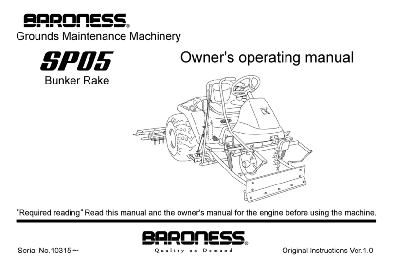
Baroness SP05 Setup guide

Bunker rake
SP05
Serial No.#10001~
[Front Blade]
Assembly and Installation manual
Thank you for purchasing this Baroness product.
This manual describes how to handle this product and make adjustments.
Please be sure to carefully read and fully understand the owner’s manual and this manual before
use.
This machine was shipped after a thorough inspection. However, the performance of the machine is
greatly affected by handling and daily maintenance, such as inspection and adjustments before and
after operation. Please handle this machine properly and perform necessary inspection and
adjustments before and after operation in order for the product to fulfill its original function and
ensure safe operation.
For operation and inspection, refer to the owner’s manual. For necessary parts, refer to the parts
catalogue.
Trädgårdsteknik AB
Caution
The information described in this manual is subject to change without prior notice for
improvement. When replacing parts, be sure to use genuine Baroness parts or parts
designated by Trädgårdsteknik AB. Note that the Baroness product warranty may
not apply to defects caused by the use of parts from other companies.
This symbol is accompanied by the word "Danger," "Warning," or "Caution." All labels with this symbol
describe important safety precautions, so please read such labels carefully and only operate the machine
after you have understood them completely. Failure to adequately follow these safety precautions may cause
an accident.
Danger:
This symbol indicates that serious injury or death will occur if the warning is ignored.
Warning:
This symbol indicates that serious injury or death may occur if the warning is ignored.
Caution:
This symbol indicates that injury or damage to property may occur if the warning is ignored.
1. Before installation, removal, adjustments, etc., park the machine on a level surface. Set the parking brake,
stop the engine, and remove the key. Ensure that all the parts have come to a complete stop.
2. Keep your hands and feet away from moving parts.Avoid performing work with the engine running. Keep
other people away from the machine during work.
3. If necessary, use appropriate chain blocks, hoists, or a jack. If the machine is lifted up, ensure that it is
supported by jack stands or appropriate blocks.
4. When replacing parts or installing accessory parts, use genuine BARONESS parts.
5. Never start the engine in a closed room. Doing so could cause carbon monoxide poisoning.
When installing, removing, and adjusting optional equipment and attachments, observe the
following safety instructions to ensure safe operation.
SP05----AM01USZ
1
Installing Optional Equipment for the SP05
Front Blade
Intended use: The front blade section is used to restore the sand that has been lost due to heavy rain, etc.
This can be finely and easily adjusted by hand.Operating width: 80 cm (31 in.)
Check that all parts are included. The following parts are included in the package.
Should any part be missing or damaged, please contact the dealer you purchased it from.
Front blade Ass’y
SP160EA0820Z0
1
Front blade Arm
SP160EA0810ZD
Qty:2
2
3.2SPHC Metal Washer 1035
K5073210352
Qty 2
3
10S Washer
K0200100002
Qty:7
4
10 Bolt 20
K0000100202
Qty:2
5
Front blade Lever
Qty:1
6
Front blade
Qty:1
7
Delta Pin9
K0450000028
Qty:2
8
Arm Backing Plate COMP
Qty:1
9
10 Washer
K5000100002
Qty:1
SP05----AM01USZ
2
10
10 Bolt 25
K0000100252
Qty:1
11
Connecting shaft
Qty:2
12
10 Nut
K0100100002
Qty:4
13
2.9 Round Spring Hook 3895
K103000026D
Qty:2
Tightening torque
Required tightening
torque Nominal diameter Appropriate tightening torque [General bolts Strength class: 4.8]
N-m kgf-cm lb-in
- M6 7–9
71.38~91.77 61.96~79.66
- M8 14–19
142.76~193.74 123.91~168.17
M10 29–38
295.71~387.49 256.68~336.34
Caution
When tightening bolts, refer to the above table. We will not be held responsible for any damage
resulting from improper or excessive tightening, etc.
SP05----AM01USZ
3
SP05
Installing the Front Blade Section
Steps Illustrations Descriptions
1
Apply grease to part B and parts C of the left and
right frames and install the front blade arms (1) in
the correct direction (grease nipple A).
2 After installing the front blade arm (1), secure it
with the washer (2), S washer (3), and bolt (4).
3 Firmly support the light ass’y (E) and remove the
light mounting bolts (D).
4
Secure the front blade lever (5), the light ass’y (E),
and the light mounting bolts (D) again in this order.
*When securing them, pass the light cable (F)
through the elongated hole on the frame so that the
cable is not caught in the frame.
SP05----AM01USZ
4
SP05
Installing the Front Blade Section
Steps Illustrations Descriptions
5
Apply grease to part G of the front blade (6) and
install the front blade ass’y to the front blade arms
(1).
6 Install the delta pin (7) to part H on both sides.
7
Install the arm backing plate COMP (8) to part I
located at the right side of the frame (the right side
of the machine) with the washer (9), S washer (3),
and bolt (10).
8
Adjust the arm backing plate COMP (8) so that the
distance between the grip of the front blade lever
(5) and the upper surface of the step sheet is about
25 mm (1 in.) and secure it with the bolt (10).
Adjust the arm backing plate COMP (8) so that
there is a little clearance when the grip is held and
so that the grip is easy to hold.
SP05----AM01USZ
5
SP05
Installing the Front Blade Section
Steps Illustrations Descriptions
9
The connecting shaft (11) is set as shown in the
illustration when the machine is shipped.
Be careful to install the connecting shaft (11) in the
correct direction. One points towards J (the front
blade arm (1)) and the other end points towards K
(the upper part of the front blade lever (5)).
10
Mount the connecting shaft (11) to the front blade
arm (1) with the S washer (3) and nut (12).
*Be careful to install the connecting shaft (11) in
the correct direction.
11
Mount the connecting shaft (11) to the upper part of
the front blade lever (5) with the S washer (3) and
nut (12). (Temporarily tighten the washer and nut
as the front blade needs to be adjusted later.)
*Be careful to install the connecting shaft (11) in
the correct direction.
12
Adjust the connecting shaft (11) so that the position
of the front blade lever is maintained and the
distance between the bottom of the front blade
section and the ground is about 200 mm (8 in.)
when the front blade section is fully raised.
Adjust the connecting shaft (11) so that the left and
right sides of the front blade move synchronously
when the front blade section is fully lowered on a
level surface.
SP05----AM01USZ
6
SP05
Installing the Front Blade Section
Steps Illustrations Descriptions
13
Remove the S washer (3) and nut (12), loosen the
nut (L), and rotate the L-ball (M) and screw shaft
(N) to the left and right to adjust the length of the
connecting shaft (11).
After adjusting the front blade section, install and
fully tighten the S washer (3) and nut (12).
14
Insert the spring hook (13) into the frame (O) (the
middle hole of the five holes) and part P of the
front blade arms. This completes the installation.
*The spring tension can be adjusted by inserting
the spring hook into a different hole. Adjust the
spring hook to the desired tension.
Removing the Front Blade Section (See the illustrations for installing the front blade section.)
1. Remove the spring hook (13) from the frame (O) and part P of the front blade arms.
2. Remove the connecting shaft (11) from the upper part of the front blade lever (5) and front blade arms (1).
3. Remove the delta pin (7) and then remove the front (6) from the front blade arms (1).
4. Remove the washer (2), S washer (3), and bolt (4), and then remove the front blade arms (1).
5. Remove the light mounting bolt (D) and then remove the front blade lever (5).
6. Re-mount the light ass’y (E) with the light mounting bolt (D).
7. Remove the washer (9), S washer (3), and bolt (10) from the right side of the frame (the right side of the
machine), and then remove the arm backing plate COMP (8).

Other manuals for SP05

4

Other Baroness Farm Equipment manuals

Baroness LM351 Operation manual

Baroness

Baroness LM351 Operation manual

Baroness LS60 Operation manual

Baroness

Baroness LS60 Operation manual

Baroness LS62 Operation manual

Baroness

Baroness LS62 Operation manual

Baroness SP05 Operation manual

Baroness

Baroness SP05 Operation manual

Baroness LH52 Operation manual

Baroness

Baroness LH52 Operation manual

Baroness TDA1200 User manual

Baroness

Baroness TDA1200 User manual

Popular Farm Equipment manuals by other brands

IronCraft FDM44 Operation and parts manual

IronCraft

IronCraft FDM44 Operation and parts manual

Case IH WD1903 Service manual

Case IH

Case IH WD1903 Service manual

Alice's Garden CHABO CKC912BN manual

Alice's Garden

Alice's Garden CHABO CKC912BN manual

Dhollandia DH-RMM 25 installation manual

Dhollandia

Dhollandia DH-RMM 25 installation manual

Demco 1122 Operator's manual

Demco

Demco 1122 Operator's manual

Chapman BT500 Original instructions

Chapman

Chapman BT500 Original instructions

Poettinger TOP 380 N Operator's manual

Poettinger

Poettinger TOP 380 N Operator's manual

Agrio Mamut 21 Instructions for use

Agrio

Agrio Mamut 21 Instructions for use

DuraTech Industries Haybuster Balebuster 2620 Operating Instructions and Parts Reference

DuraTech Industries

DuraTech Industries Haybuster Balebuster 2620 Operating Instructions and Parts Reference

Vicon Andex 1104 operating manual

Vicon

Vicon Andex 1104 operating manual

enorossi EASY RAKE 10 Use and maintenance manual

enorossi

enorossi EASY RAKE 10 Use and maintenance manual

Headsight CORN GTS 09020901f installation manual

Headsight

Headsight CORN GTS 09020901f installation manual

REDEKOP MAV-500 installation guide

REDEKOP

REDEKOP MAV-500 installation guide

Kamikaze KV 4 user manual

Kamikaze

Kamikaze KV 4 user manual

Z.I.P.P.ER MASCHINEN ZI-MD500HST user manual

Z.I.P.P.ER MASCHINEN

Z.I.P.P.ER MASCHINEN ZI-MD500HST user manual

FarmTek Growers Supply HydroCycle Vertical Aeroponic... Important information

FarmTek

FarmTek Growers Supply HydroCycle Vertical Aeroponic... Important information

Toro Reelmaster 33452 Operator's manual

Toro

Toro Reelmaster 33452 Operator's manual

Kerbl Duo 18810 Instructions for use

Kerbl

Kerbl Duo 18810 Instructions for use

manuals.online logo
manuals.online logoBrands
  • About & Mission
  • Contact us
  • Privacy Policy
  • Terms and Conditions

Copyright 2025 Manuals.Online. All Rights Reserved.