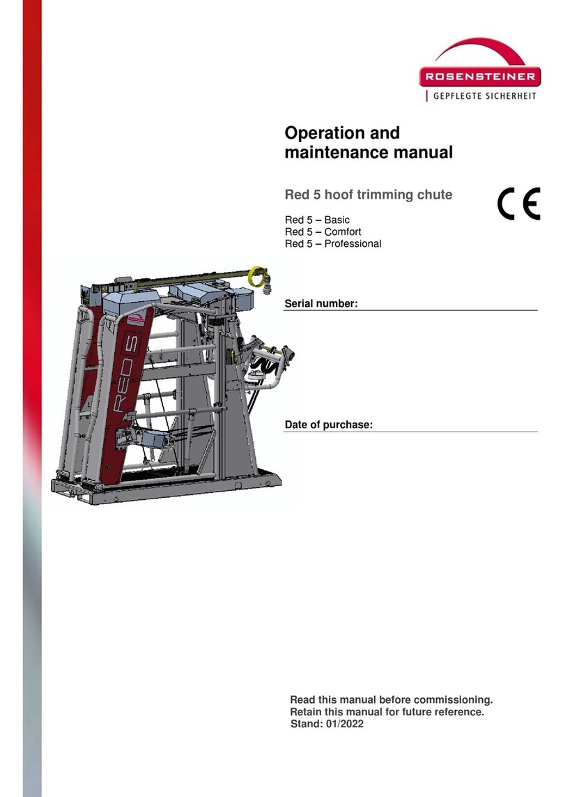
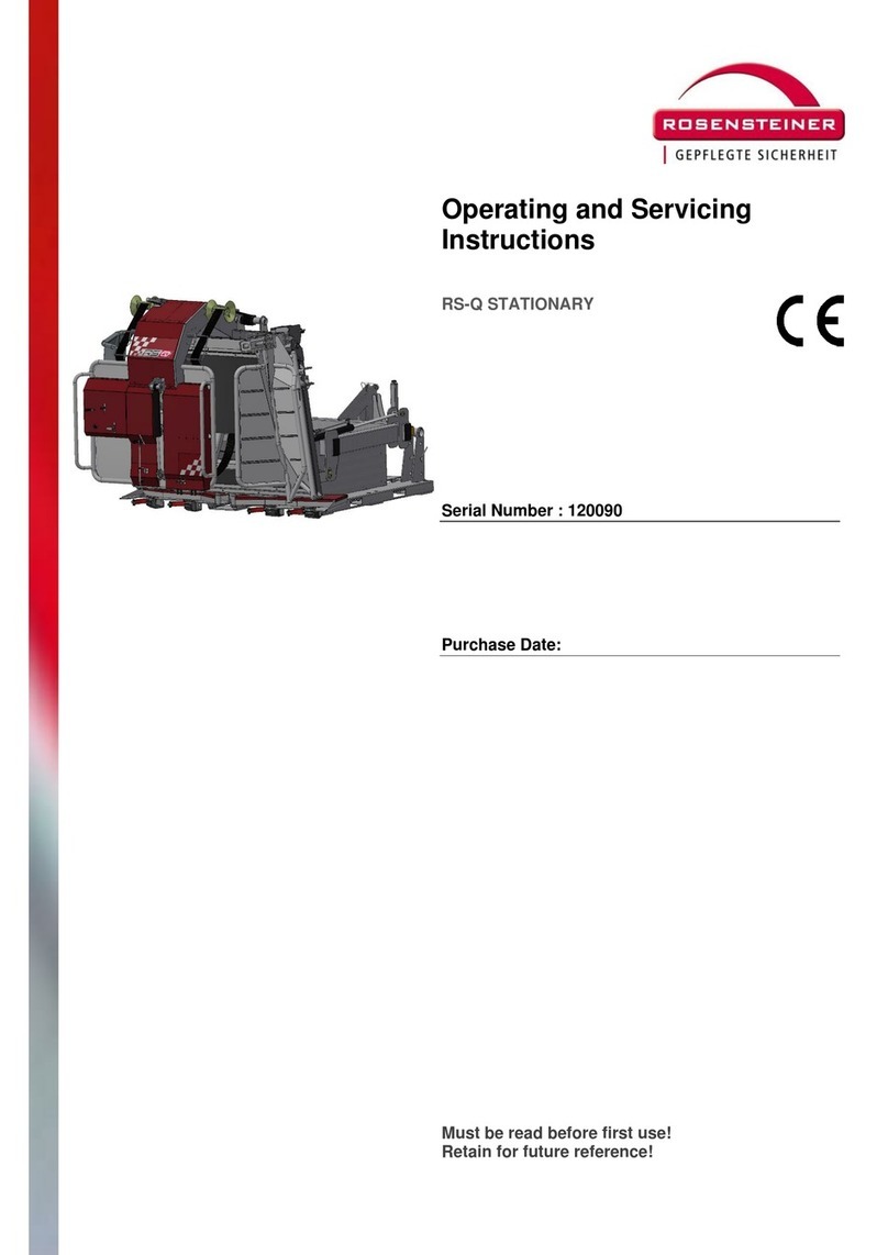
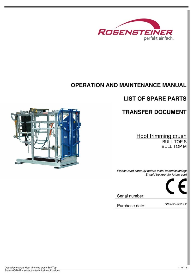
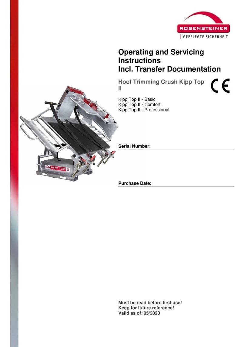
Rosensteiner RED Q Guide

Operating Instructions Hoof Trimming Crush RED Q - 1 of 31 -
Version 10/2014 – subject to technical modifications
OPERATION AND MAINTENANCE MANUAL
LIST OF SPARE PARTS
TRANSFER DOCUMENT
Hoof trimming crush
RED Q
Please read carefully before initial commissioning!
Should be kept for future use!
as of serial no. 00036
Serial number:
Purchase date:

OPERATION AND MAINTENANCE MANUAL – -
INHALTSVERZEICHNIS
Operating Instructions Hoof Trimming Crush RED Q - 2 of 31 -
Version 10/2014 – subject to technical modifications
INHALTSVERZEICHNIS
Inhaltsverzeichnis ............................................................................................................................................................................. 2
1.Introduction ............................................................................................................................................................................... 3
1.1.About this product.............................................................................................................................................................. 3
1.2.Intended use...................................................................................................................................................................... 3
1.3.Selected examples of improper use................................................................................................................................... 3
1.4.EU- Declaration of conformity............................................................................................................................................ 4
1.5.Warranty ............................................................................................................................................................................ 4
1.6.Technical data.................................................................................................................................................................... 4
1.7.Type plate.......................................................................................................................................................................... 5
1.8.Structure and scope of the operation manual .................................................................................................................... 5
1.8.1.Structure........................................................................................................................................................................ 5
1.8.2.Target group.................................................................................................................................................................. 5
1.8.3.Changes to this operation manual................................................................................................................................. 5
1.8.4.Storage of this operation manual................................................................................................................................... 5
1.8.5.Spatial limits .................................................................................................................................................................. 5
1.8.6.Time limits ..................................................................................................................................................................... 5
1.8.7.Workplaces operation.................................................................................................................................................... 5
1.8.8.Explanation of the information and safety instructions................................................................................................... 6
1.8.9.Pictograms in the operation manual and on the machine.............................................................................................. 6
2.Transportation........................................................................................................................................................................... 6
2.1.Attaching a hoof trimming crush to a traction engine......................................................................................................... 6
2.2.Transporting a hoof trimming crush using a traction engine .............................................................................................. 7
2.3.Removing a hoof trimming crush from a traction engine and setting it down..................................................................... 7
3.Commissioning / Operation...................................................................................................................................................... 7
3.1.Device overview / main controls......................................................................................................................................... 7
3.2.Safety information before commissioning of the machine.................................................................................................. 8
3.3.Danger area/working area ................................................................................................................................................. 8
3.4.Procedures for the commissioning of the hoof trimming crush........................................................................................... 9
4.Cleaning ..................................................................................................................................................................................... 9
5.Maintenance / Service / Repairs............................................................................................................................................... 9
5.1.Safety information.............................................................................................................................................................. 9
5.2.Electrical hazards............................................................................................................................................................. 10
5.3.Maintenance and care ..................................................................................................................................................... 10
6.Spare parts............................................................................................................................................................................... 10
7.Recurring inspections............................................................................................................................................................. 11
8.Scope of delivery / accessories ............................................................................................................................................. 11
List of spare parts…………………………………………………………………………………………………………………………… 13
OPERATION AND MAINTENANCE MANUAL – -
INTRODUCTION
Operating Instructions Hoof Trimming Crush RED Q - 3 of 31 -
Version 10/2014 – subject to technical modifications
1. INTRODUCTION
1.1. ABOUT THIS PRODUCT
Thank you for purchasing the Rosensteiner hoof trimming crush "Red Q", a piece of equipment with pioneering technology for
trimming animal hooves. The hoof trimming crush serves for periodic, expert and economic hoof trimming in a posture which is
ergonomical, functional and fatigue-proof for the carer.
The hoof trimming crush is generally referred to as work equipment in this operation manual.
The work equipment and its fittings are in accordance with the state of the art at the time of placing on the market.
However, residual risks exist. Insofar as possible, we have constructively reduced the risks to health which are
associated with these hazards.
This document contains important information and serves as a guideline for safe operation inclusive of all activities
which are necessary for operation, such as handling, maintenance or service. Through its observance you will be able
to avoid dangers and to increase the lifetime of the work equipment. It is prohibited for the customer to change it.
The documentation of the individual subcontractors, and especially the information and details contained therein, is
fully valid and are to be observed.
The manufacturer does not accept any liability for damages that arise from failure to comply with details and
information contained in the manuals, or from improper usage.
We compiled the documentation with great care. However, it may contain minor deviations. Please inform us of these.
CAUTION
Unauthorized modifications (structural, functional or procedural) and the use of components and auxiliary components
on the work equipment exclude the liability of the manufacturer.
WARNING
Intended alterations, changes to the work equipment described, require a further analysis of the dangers and an
evaluation of the risks! Original spare parts and accessories are designed specially for this work equipment. We
particularly emphasize that original parts and accessories which are neither specified nor supplied by us are also
neither tested nor released by us. The fitting and/or usage of such products may negatively change or influence the
given constructive characteristics of your work equipment. The manufacturer accepts no liability whatsoever for
damage caused by the use of non-original parts and accessories.
1.2. INTENDED USE
The Red Q hoof trimming crush is intended solely for trimming animal hooves.
The hoof trimming crush is suitable for bovine animals from 300 kg to 1000 kg maximum.
Any operation which deviates from "the intended use" is an improper use and therefore prohibited. This is also valid for components
of this work equipment.
1.3. SELECTED EXAMPLES OF IMPROPER USE
Any usage that deviates from the "intended use" or which goes beyond the defined scope of utilization.
Operation of the work equipment that is not in compliance with the requirements of the safety and risk aspects and with full
observance of the operation manual. This is also valid for malfunctions which arise as a result of defective, improper or
unauthorized work on/with the work equipment.
Each alteration, bypassing or shutting off of fittings on the work equipment which serve the proper functioning and the active and
passive safety.
Operation of the work equipment in a non-perfect condition technically.
Failure to remedy faults that impair the safety before using the work equipment.
Use of inappropriate auxiliary equipment and tools.
As a general principle, the manufacturer shall not be liable for damage resulting from improper use.

OPERATION AND MAINTENANCE MANUAL – -
INTRODUCTION
Operating Instructions Hoof Trimming Crush RED Q - 4 of 31 -
Version 10/2014 – subject to technical modifications
1.4. EU- DECLARATION OF CONFORMITY
Manufacturer and responsible for documentation:
ROSENSTEINER
Landmaschinenbau Ges.m.b.H.
Zehetner 26a
A-4596 Steinbach / Steyr
Phone +43(0)7257/7071
hereby declares that the machine described in the accompanying operation manual:
Type: Red Q
Description: Red Q Hoof Trimming Crush
Brand: Rosensteine
r
is in accordance with the provisions of Directive 2006/42/EU (for Machinery).
Steinbach, 1st March 2013
Andreas Rosensteiner, owner
1.5. WARRANTY
The company Rosensteiner Landmaschinenbau GesmbH assumes warranty under the following terms and conditions:
1) The warranty includes the function and quality of the device. The warranty does not cover wear and tear.
2) Time of warranty is 1 year from the day of delivery to the customer. All warranty claims received within the warranty period by
the retailer or in the plant, Zehetner 26a, A-4596 Steinbach, shall be processed.
3) Warranty claims must be submitted immediately to the retailer or manufacturer if defects appear in the material or in the
workmanship during the warranty period.
4) The retailer must be shown the defective device or part. A subsequent repair or replacement may only take place in agreement
with Rosensteiner. Expenses made without explicit consent will not be covered by the manufacturer. Defective parts are to be
stored with the retailer as agreed upon, or sent to Rosensteiner. The customer must bring the device to the retailer free of
carriage charges.
5) No warranty claims will be considered if the device is damaged or destroyed by force majeure. Note: Warranty claims will lapse
in the case of damages as a result of improper handling, overload, attachment to oversized carrier vehicles or non-implemented
maintenance and care!
6) Warranty claims shall only be processed when the contract of purchase, invoice or delivery note and the device number are
submitted together with the device.
7) In fulfilling the warranty, the device will be repaired or exchanged for a functional equivalent.
8) Further claims, in particular damages and loss in any form whatsoever which are the result of device usage, are excluded.
9) If a replacement is made by us in accordance with this warranty, warranty claims against the retailer as the seller will be
eliminated.
1.6. TECHNICAL DATA
Machine type Red Q Hoof Trimming Crush
Dimensions 2050/2155/2095 (L/W/H)
Recommended animal size 300-1000 kg
Dead weight 960kg
Attachment Three-point tractor hitch Cat II
Cushioning Rubber mat Cow Comfort
Drive via 220V/2.2kw Electro-hydraulics
Finish Galvanized/powder-coated

OPERATION AND MAINTENANCE MANUAL – -
INTRODUCTION
Operating Instructions Hoof Trimming Crush RED Q - 5 of 31 -
Version 10/2014 – subject to technical modifications
1.7. TYPE PLATE
The type plate is attached to the control lever near the main switch and shows the type designation and serial number!
1.8. STRUCTURE AND SCOPE OF THE OPERATION MANUAL
1.8.1. Structure
This operation manual was created in accordance with the Directive 2006/42/EU and the resulting regulation MSV 2010, implemented
in Austria. The operation manual in its present form will support you in getting to know the technical details of the machine, in operating
the machine properly and safely, in maintaining it and in using it in the intended fields of application.
1.8.2. Target group
The operation manual is aimed at those people who are familiar with a traction engine, with the attachment of additional devices, with
the transport of attachment devices using a traction engine, the commissioning and operation of these, and who possess the
appropriate qualifications for their jobs and functions, i.e. those people who can evaluate the jobs and possible dangers because of
their professional training, knowledge and experience.
Each person who is involved with work on the machine – e.g. operation, maintenance, transport – must:
have read and understood these operating instructions before working with the machine,
observe the contained instructions and safety information.
1.8.3. Changes to this operation manual
The present operation manual describes the condition of the work equipment at the time of creation of the operation manual.
1.8.4. Storage of this operation manual
This operation manual must always be stored at the place of action of the work equipment and must be readily accessible for all
people using the work equipment! If this operation manual gets lost, please request a replacement from your retailer. If you sell your
machine, please remember to include the operation manual. It is a statutory component of your machine. You can also find the
operation manual on our homepage www.rosensteiner.at
1.8.5. Spatial limits
This machine is designed for mobile operation at different places of use.
1.8.6. Time limits
Because of the stress on the work equipment, attention must be paid to the durability of the components used, with regards to
reliability, breakdown susceptibility and their operating limits. The following service life phases are not dealt with in these operating
instructions:
Manufacture and transport (to the customer / user)
Maintenance work on the work equipment and its components in workshops
Work which requires the competence of the operator (welding work, electrical work,...)
1.8.7. Workplaces operation
Recommended space requirement for the Red Q

OPERATION AND MAINTENANCE MANUAL – -
TRANSPORTATION
Operating Instructions Hoof Trimming Crush RED Q - 6 of 31 -
Version 10/2014 – subject to technical modifications
1.8.8. Explanation of the information and safety instructions
Useful additional information in continuous text is marked with accompanying info button
SIGNAL
WORD
Type and source of danger and the accompanying risks!
Possible consequences for people, machine parts, tools and work piece – residual risk!
Measures to avoid danger to life and limb and to reduce the residual risk.
SIGNAL
WORD Explanation
NOTE Warns against a potentially dangerous situation in which the unit or something in its environment could be damaged.
CAUTION Warns against a potentially dangerous situation which could lead to light bodily harm or damage to property.
WARNING Warns against a potentially dangerous situation which could lead to severe bodily harm or death.
DANGER Warns against an imminent danger which will lead to severe bodily harm or death.
1.8.9. Pictograms in the operation manual and on the machine
Never enter the danger zone between the attachment and the machine!
Danger of crushing!
Read and observe the operation manual and safety information before commissioning the machine!
Turn the motor off before repair, maintenance and cleaning work and pull out the plug!
Keep sufficient distance from the electric high voltage line!
Machine with wheel chocks before uncoupling or setting down!
Avoid uneven surfaces and slopes where the device could slip, tip or fall over!
Before maintenance and repair work, switch off the motor and remove the key!
Beware of fluid escaping under high pressure. Please observe the information in the technical manual!
2. TRANSPORTATION
2.1. ATTACHING A HOOF TRIMMING CRUSH TO A TRACTION ENGINE
WARNING
To transport the hoof trimming crush with the tractor, first mount the balls of the lower link on the quick coupling shaft.
Then back the tractor up to the device and make sure that there is nobody in the danger zone, in particular between
the tractor and the hoof trimming crush, lift the lower link until the balls engage at the lower link. Now hang in and
secure the upper link.
To be observed while attaching:
Before attaching the hoof trimming crush, make sure that the tractor has enough frontal weight.
Never step between the tractor and the hoof trimming crush while coupling up, there is a danger of crushing.
Use suitable security bolts to mount the hoof trimming crush with the lower / upper link support and check that
there is a tight fit in the suspension.
While operating the tractor hydraulics (upper link, lower link), ensure a secure position with sufficient distance
from dangerous movements, under no circumstances stand on parts of the tractor (lower link,...) or on the hoof
trimming crush.
Do not step between the hoof trimming crush and the tractor when the traction engine is running.
Check transportation position

OPERATION AND MAINTENANCE MANUAL – -
COMMISSIONING / OPERATION
Operating Instructions Hoof Trimming Crush RED Q - 7 of 31 -
Version 10/2014 – subject to technical modifications
2.2. TRANSPORTING A HOOF TRIMMING CRUSH USING A TRACTION ENGINE
WARNING
Keep a sufficient distance from the electric high voltage line during transport.
When transporting the device on public roads, please observe the road traffic regulations of your country and
affix the lights or warning signs to the device as prescribed by law.
For day use, two warning lights must be affixed on the left and right rear of the hoof trimming crush in such a
manner that the rear lighting of the hauler is not covered. For night use, a light rail with complete element
illumination (lights left and right as on the hauler) must be affixed to the rear of the hoof trimming crush.
2.3. REMOVING A HOOF TRIMMING CRUSH FROM A TRACTION ENGINE AND SETTING IT DOWN
WARNING
Proceed as follows for the set-down of the hoof trimming crush:
Drive on to a level storage area.
Secure the tractor against rolling (hand brake, brake wedge).
Lower the hoof trimming crush. When setting down the hoof trimming crush, make sure that it is tip- and slip safe,
especially when it is to be set down at an elevation on scales, pallets etc.
Free the upper link chain first, then the lower link chain.
3. COMMISSIONING / OPERATION
3.1. DEVICE OVERVIEW / MAIN CONTROLS
Pos. Designation Item Designation
01 Cat II 3-point hitch 02 Bracket for manual transport
wheels
03 Switch cabinet 04 Head support
05 Foot holder 06 Head catching device
07 Belly strap 08 Lifting panel control
09 Motor switch 10 Belly belt roll-up control
11 Motor switch 12 Lead-in gate
13 Lead-in gate control 14 Catching device control
15 Catching device swivelling
control 16 Belly belt roll-up
17 Angle grinder mount 18 Blade holder
19 Sockets 230 V 20 Toolbox

OPERATION AND MAINTENANCE MANUAL – -
COMMISSIONING / OPERATION
Operating Instructions Hoof Trimming Crush RED Q - 8 of 31 -
Version 10/2014 – subject to technical modifications
3.2. SAFETY INFORMATION BEFORE COMMISSIONING OF THE MACHINE
NOTE
For the first commissioning you should be helped by a person who already has experience with the device and
with the trimming of animal hooves.
Do not carry out hoof trimming just after feeding!
WARNING
The operation manual and the safety information must be carefully read and observed before commissioning
and operating this work equipment.
If the hoof trimming crush is not mounted on a towing vehicle, it must always be anchored in the base with a
base console!
Ensure sufficient ventilation when carrying out the work.
When working on the hoof trimming crush with the tractor attached, switch off the tractor, lock it against starting
up (remove the ignition key), and secure it against rolling off (parking brake, wheel chock).
The device may only be operated by people who are familiar with the intended field of application and who are
used to bovines.
Before use, a general visual inspection of the hoof trimming crush must be carried out in case of possible
changes.
Check whether the hoof trimming crush is set down on level ground.
Check of the hoof trimming crush for loose (especially screw connections) and hanging parts.
Check of the hydraulic system for damages, especially the transmission lines / tubing.
Check belts for wear and tear.
Check the condition of all protection devices.
Check screw connections and tighten if necessary.
The device may only be operated with suitable protection measures against too high touch voltage. FI-switch
30mA trigger voltage.
Visually inspect electrical equipment for damages.
Check whether the electric inspection is within the year interval (yearly inspection of the electric installation by
experts is required).
During operation with the emergency program, the appliance must be disconnected from the power supply.
Inspect the work space and make sure that no unauthorized person is in the work space - pay special attention
to children.
Use personal protective equipment!
3.3. DANGER AREA/WORKING AREA
Access to the danger area (hoof crush
installation space + 2 m clearance) is only
permissible for trained persons
The operator must keep any other persons clear
of the danger area.

OPERATION AND MAINTENANCE MANUAL – -
CLEANING
Operating Instructions Hoof Trimming Crush RED Q - 9 of 31 -
Version 10/2014 – subject to technical modifications
3.4. PROCEDURES FOR THE COMMISSIONING OF THE HOOF TRIMMING CRUSH
Please see device picture(s) for the following numerations:
1) Attach the hoof trimming crush Cat II three-point hitch (01) to the tractor's lower and upper links (see also Transport
chapter).
2) Pull the power cable from the switch cabinet (3) and connect the Red Q to the power supply
3) Switch on the motor switch (9) and use the lift panel control (8) to tilt the lift panel to vertical position. Beware of
fluid escaping under high pressure. Immediately consult a doctor in case of injury due to escaping hydraulics!
4) Use the pushing gate control (12) to swivel the pushing gate (13) to lead-in position.
5) Loosen the belly-belt roll-up (16) and move the belts (7) into position.
6) Swivel the catcher bar (6) up (lead-out position); move the head support (4) into working position, and secure with
bolts.
7) Move the catcher bar (6) back down into catching position. Make sure there are no persons in the swiveling area
(risk of injury)
8) Drive the cow into the stand, close the pushing gate (12) and lightly close the catcher bar (6) to hold the head in
position.
9) Tighten the belly belt (7) at the rear (behind the hip bones) manually, until the belt rest lightly against the cow's
body. Now tighten through half a revolution. Tighten the belly belt at the front manually, until the belt rest lightly
against the cow's body.
10) Tighten the belt hydraulically up to the stop
11) Tip table 45°. To do so push up the lever (8) with your left hand (keeping out of the rear foot danger zone).
12) Tighten feet using foot holder (5).
13) To adjust the height of the foot holder, loosen the clamping screws; set the foot holder to a suitable height and
fasten again with the clamping screw.
14) Tilt the lifting panel to horizontal position.
15) Perform hoof trimming. Wear goggles and safety gloves when using rotating tools.
16) Release the foot holder clamp, tilt the table back to 45° position, and unstrap the feet. Push back foot holder
completely.
17) Lower the table to the stop, release the belts, open the catching device, and drive the animal out.
4. CLEANING
NOTE
Observe the safety information in the safety data sheet for detergents/disinfectants
remove cleaning waste water in accordance with regulations in the country of use.
Wear protective goggles
Do not use detergents or disinfectants that attack paint, galvanization or rubber!
5. MAINTENANCE / SERVICE / REPAIRS
5.1. SAFETY INFORMATION
CAUTION
Service work may only be carried out by qualified and trained personnel or by the manufacturer himself.
Maintenance and service work may only be carried out when there is sufficient lighting present for the work to be
carried out.
WARNING
Maintenance work may only be carried out when fully set down.

OPERATION AND MAINTENANCE MANUAL – -
SPARE PARTS
Operating Instructions Hoof Trimming Crush RED Q - 10 of 31 -
Version 10/2014 – subject to technical modifications
5.2. ELECTRICAL HAZARDS
DANGER
Contact with live parts.
Effects of electrical power on humans.
Compliance with the statutory regulations for installation, operation, service and inspection of electrical operating
material.
Only allow skilled electricians to carry out work.
Skilled personnel must service damaged installations immediately!
Use of suitable plugs, couplings
Recurring inspections
Ensure that the device is completely turned off and secured against restarting before opening the electrical device
casing!
The service personnel must be acquainted with specialist standards and regulations.
DANGER
INJURIES DUE TO UNEXPECTED CHANGE IN OPERATING STATES.
Check the loosened screw connection for a secure fit before starting up
Loosening screw connections: When opening screw connections, slowly open these to reduce pressure in the line.
Opening drain points with screw connections: Only remove threaded joints of drain points if system is
depressurized!
The pressure must have fully dissipated before opening pipe connections and pressurized systems.
5.3. MAINTENANCE AND CARE
The following measures increase the operational safety and lifetime of your device:
Regularly lubricate all pivot points and lubricating nipples after pressure cleaning.
Check the hydraulic oil fill level from time to time and replenish, if necessary. Oil change 1 year after start-up. Further
oil changes every 2 years (also empty the cylinder).
Original filling: Hydraulic oil HLP10, amount: 14 liters.
Check screw connections (in particular also at the hydraulic system) and tighten again after every fifth start-up and
as necessary.
Lubricate thread of the foot holder locking screwing.
Oil rotating points of the foot holder.
Repair or replace damaged parts immediately. Work with damaged parts can entail a risk for you and the animal.
Even if stored properly and subject to permissible loads, hoses and hose lines will undergo a natural aging. Their
service life is consequently limited. The service life of a hose line including a potential storage time for the hose line
should not exceed six years. The storage time should not exceed two years for this. According to DIN 20 066.
We recommend treating the working area including the foot holder guides with a biologically degradable form oil as
this offers good corrosion protection and keeps all moving parts moving smoothly
NOTE
6. SPARE PARTS
NOTE
Original parts are to be used to replace a component of the machine. Spare and wear parts for original components
and accessories which are not supplied by the manufacturer of the machine are not tested and approved by the
manufacturer.
The fitting and/or usage of such products may change the given constructive characteristics of the machine and
endanger its' safety.
The manufacturer accepts no liability whatsoever and the right to warranty will expire for damages or consequential
damages caused by the use of non-original parts and accessories or the inappropriate fitting or replacement of original
parts and accessories.
Once the warranty terms have elapsed, we recommend the usage of original parts to ensure continuous performance
of the machine. For warranty claims please contact your local sales and service partner.

OPERATION AND MAINTENANCE MANUAL – -
RECURRING INSPECTIONS
Operating Instructions Hoof Trimming Crush RED Q - 11 of 31 -
Version 10/2014 – subject to technical modifications
7. RECURRING INSPECTIONS
NOTE
The electric installation of the machine is to be inspected yearly by an expert.
8. SCOPE OF DELIVERY / ACCESSORIES
Standard equipment:
Hydraulic pushing gate
Hydraulic head catching device
Hydraulic belly belt roll-up
Hydraulic lifting panel
Toolbox with toolholder and 3 sockets
Cat II three-point hitch
Fork lift bracket 3-part
Quick-coupling foot holder: lowering – gentle on livestock and safe
Art. No. Type Description
70 000 Red Q
According to standard equipment
Art. No. Accessories
70 170 4 slot-in wheels with pneumatic tires for manual transport and loading on a trailer + lifting axle

LIST OF SPARE PARTS
Hoof trimming crush
RED Q
Please read carefully before initial commissioning!
Should be kept for future use!
as of serial no. 00036
Serial number:
Purchase date:

LIST OF SPARE PARTS
RED Q
List Of Spare Parts Hoof Trimming Crush RED Q - 13 von 31 -
Version: 07/2013 – Subject to technical changes
1. CONTROL LEVER
Pos. Designation Quantity Art. No.
1 Washer M12 24 00830443
2 Lock nut M12 12 00830543
3 Lock nut M8 15 00811043
4 Washer M8 47 00811743
5 Washer M10 2 00821043
6 Lock nut M10 1 00820943
7 Red Q control lever guide lifting panel control 1 12106031
8 Allen screw ISK M8x16 DIN912 6 00811643
9 Allen screw ISK M8x20 DIN912 33 00812043
10 Lowering restrictor retainer plate 1 15261011
11 Red Q control lever guide Lifting panel linkage bushing 2 12501831-1.1
12 Plug-in nut M8 DIN7504-K zinc plated 32 12809543
13 Circlip ø18 1 00863647
14 Hydraulic-type lubricating nipple 2 82543
15 Hexagon head bolt M12x45 8 00833543
16 KN switch IP67 - hole centre distance 110 2 12801043
17 Manual control valve 5-way 1 15900263
18 Cylinder handle 1 12805043
19/20 Angle joint CS M8 galvanized DIN71802 6 00812443
21 Lever FVR swivel 1 12505131
22 Circlip ø18x1.2 DIN471 1 12503031

LIST OF SPARE PARTS
RED Q
List Of Spare Parts Hoof Trimming Crush RED Q - 14 von 31 -
Version: 07/2013 – Subject to technical changes
23 Clevis mating piece M10 1 12804643
24 T-handle 1 12804943
25 Red Q handle lifting panel control 1 12502031-1.1
26 Clamping washer ø10 for shafts without a groove 1 12805231
27 Cover plate control lever front 1 12159631
28 Cover plate control lever top 1 12159531
29 Lever winding rod control 1 12112031
30 Plastic handle 3 00885854
31 Hexagon head bolt DIN 933 - M8x40 1 00810343
32 Hexagon head bolt DIN 933 M10x65 1 00822745
33 Hexagon head bolt DIN 933 M12x30 4 00830143
34 Red Q winding rod bearing 2 12200231-1.2
35 Control lever steel part 1 12606200
36 Allen screw M8x25 2 00811843
37 Lock nut M8 2 00811043
38 Control unit support 5-way 1 12159731
39 Gate belt screw M8x65 3 00814345
40 Lead-in gate control lever 1 12159231
41 Lead-in gate actuator bracket 1 12159331
42 Winding rod control lever shaft 1 12503231-1.1
43 Lug bearing 2 12159431
44 Bushing bearing lead-in gate actuator bracket 1 12407731
45 Threaded rod lead-in gate actuator 2 12504931
46 Bushing lead-in gate lever bearing 1 12504831
47 Threaded rod winder actuator 1 12505031
48 Linkage lifting panel control 1 12503131-1.1
49 Lowering restrictor 3/8" 2 00894873
50 Gate belt screw M8x55 1 00814346
51 Shim M10 1 00821043
52 Allen screw M8x16 1 00811643
53 U head M10 1 12804743

LIST OF SPARE PARTS
RED Q
List Of Spare Parts Hoof Trimming Crush RED Q - 15 von 31 -
Version: 07/2013 – Subject to technical changes
2. HYDRAULIC
2.1 Lifting panel
Pos. Designation Quantity Art. No.
1 High pressure hose 2SK-10 BJ18/EFR12L l=805 (Extend cyl. lifting panel) 2 12810243
2 High pressure hose 2SK-10 BJ18/EFR12L l=1300 (Retract cyl. lifting panel) 2 12810343
3 High pressure hose 2SK-6 BJ3/8"/EFR12L l=2660 (extend cyl. lead-in gate) 1 12810943
4 High pressure hose 2SK-6 BJ3/8"/EFR12L l=2770 (retract cyl. lead-in gate) 1 12810843
5 High pressure cylinder dual action SL40/25x200 1 00996674
6 High pressure hose 2SK-6 BJ18EFR12L l=2880 (swiveling cylinder catcher) 1 12810643
7 High pressure hose 2SK-6 BJ18EFR12L l=2880 (swiveling cylinder catcher) 1 12810643
8 High pressure cylinder dual action SL50/28x300 1 00899663
Articulated lug for cylinder 1 00893163
9 High pressure cylinder dual action SL50/28x400 2 19913773
Articulated lug for cylinder 1 00893163
10 High pressure hose 2SK-6 BJ1/4"/EFR12L l=3410 (retract cyl. catching device) 1 12810743
11 High pressure hose 2SK-6 BJ1/4"/EFR12L l=3410 (extend cyl. catching device) 1 12810743
12 High pressure cylinder dual action SL32/20x200 1 10929163
13 High pressure hose 2SK-10 EFR12L/EFR12L l=3280 (control unit return) 1 12811043
14 High pressure hose 2SK-10 EFR12L/EFR12L l=3600 (control panel pressure
line) 1 12811143
15 High pressure cylinder dual action SL40/22x300 1 12900943
16 Straight spigot 12L/12L 7 00991863
17 Hose holder half-shell ø14 22 00894263
18 T-piece 12L without nut 2 00991763
19 High pressure hose 2SK-10 EFR12L/EFR12L l=900 (lowering restrictor T-piece) 2 12810143
20 Hose holder half-shell ø18 20 00892263

LIST OF SPARE PARTS
RED Q
List Of Spare Parts Hoof Trimming Crush RED Q - 16 von 31 -
Version: 07/2013 – Subject to technical changes
2.2 Lifting panel
Pos. Designation Quantity Art. No.
1 Threaded joint bracket EEL 12L 12 00899261
2 Screw-in part 3/8" without nut 12 00867543
3 High pressure hose 2SK-8 BJ16/EFR12L l=1260 (retract cyl. winding bar) 1 12810543
4 High pressure hose 2SK-8 BJ16/EFR12L l=1260 (extend cyl. winding bar) 1 12810443
5 Non-return needle choke valve 3/8" 2 00894873
6 High pressure hose 2SK-10 EFR12L/EFR12L l=530 (control unit lowering
restrictor, lifting panel) 2 12810043
7 Adapter 12L 5 00894463
8 Straight spigot 12L/12L 7 00991863
Banjo screw ¼“ DIN7623 + packing rings 2 00890543
Banjo screw 3/8" DIN7623 + packing rings 2 12803943
Banjo screw M18x1.5 DIN7623 + packing rings 6 00891363

LIST OF SPARE PARTS
RED Q
List Of Spare Parts Hoof Trimming Crush RED Q - 17 von 31 -
Version: 07/2013 – Subject to technical changes
2.3 Underbody
Pos. Designation Hose length Quantity
A
rt. No.
1 Hydraulic unit 2.2 kW 1 00908866
2 High pressure hose 2SK-10 EFR12L/EFR12L / shuttle valve – bulkhead
fitting 430mm 1 12809443
3 High pressure hose 2SK-10 EFR12L/EFR12L / return locking lever socket 545mm 1 12809843
4 Non-return valve RHD 12L 1 15905463
5 Hexagon nipple 12L 2 00991863
6 Hose carrier ø18 1 00894263
7 High pressure hose 2SK-10 EFR12L/EFR12L / pivot point – shuttle valve 2120mm 1 12803443
8 High pressure hose 2SK-10 EFR12L/EFR12L / pivot point – 3-way valve 2010mm 1 12803543
9 Threaded joint bracket EEL 12L 5 00899261
10 Three-way ball valve 1 00866564
11 Adapter 90° 2 00895643
12 Adapter 12L 1 00894463
13 Socket BG3 12L – bulkhead lead-through 2 00895277
14 Shuttle valve XTWV 12L 1 00895780
15 High pressure hose 2SK-10 EFR12L/EFR12L / return line shut-off lever tank 475mm 1 12809743
Shim M10 4 00821043
Lock nut M10 Din985 4 00820943
Allen screw M10x20 Din912 4 00821243

LIST OF SPARE PARTS
RED Q
List Of Spare Parts Hoof Trimming Crush RED Q - 18 von 31 -
Version: 07/2013 – Subject to technical changes
3. HYDRAULIC CIRCUIT DIAGRAM

LIST OF SPARE PARTS
RED Q
List Of Spare Parts Hoof Trimming Crush RED Q - 19 von 31 -
Version: 07/2013 – Subject to technical changes
4. HEAD CATCHING DEVICE
Pos. Designation Quantity Art. No.
1 High pressure cylinder 32/20 EL=360 stroke=200 1 10929163
2 Lock nut M8 3 00811043
3 Shim M8 4 00811743
4 Round pipe plug Ø6/4 inch 1 00881453
5 Red Q catcher bar bolt cylinder horizontal back 1 12601500
6 Hexagon head bolt M8x35 1 00813543
7 Hexagon head bolt M8x20 2 00813043
8 Red Q guide catcher bar right 1 12200331
9 Red Q guide catcher bar left 1 12200431
10 Nut M16 DIN934 8 00841743
11 SE screw M16x70 DIN933 4 00845743
12 High pressure cylinder 50/28 300mm stroke 1 00899663
13 Guide tube catcher bar Red Q 1 12605400
14 Catcher bar Red Q Jens with reinforcement 1 12605700
15 Bolts bearing CB 1 12504331
16 Catcher bar guide spacer 2mm 1 12110931-1.1
17 Bolt cylinder CB bottom 1 12605900-1.1
Spacer bushing CB bottom 1 12407831
18 Bolt cylinder CB top 1 12605900-1.1
19 Bearing bush short horizontal cylinder CB 1 12407231
20 Bearing bush long horizontal cylinder CB 1 12407331
21 Spacer bushing cylinder CB top 2 12407431
22 Spacer bushing cylinder CB horizontal 2 12407531
23 Bolt cylinder CB horizontal 1 12606000
24 Bearing bush catcher bar 2 12407631
25 Stop buffer 50x15 rubber metal 1 00881253
26 Lock nut M10 DIN985 1 00820943
27 SE screw M8x60 DIN933 zinc plated 1 00813643

LIST OF SPARE PARTS
RED Q
List Of Spare Parts Hoof Trimming Crush RED Q - 20 von 31 -
Version: 07/2013 – Subject to technical changes
28 Hexagon head bolt M8x25 1 00812743
5. HEAD BAR
Pos. Designation Quantity Art. No.
1 Round pipe plug Ø6/4 inch 1 00881453
2 Lock nut M10 2 00820943
3 Shim M10 2 00821043
4 Bearing shell plastic 1 12158931
5 U-bolt 6/4 inch 1 90909543
6 Red Q head bar 1 12602900-1.5
7 Split pin 10x45 1 00861843
Table of contents
Other Rosensteiner Farm Equipment manuals

Rosensteiner
Rosensteiner 901557 User manual

Rosensteiner
Rosensteiner VET PRO STATIONARY User guide

Rosensteiner
Rosensteiner Red 5 User manual

Rosensteiner
Rosensteiner Kipp Top II Basic User guide

Rosensteiner
Rosensteiner Red 5 User manual

Rosensteiner
Rosensteiner BULL TOP S User manual

Rosensteiner
Rosensteiner RS-Q STATIONARY User guide