Rabe Combi-Digger Series User manual

Operating Instructions
Subsoiler
Combi-Digger
Order-No. 9900.01.44GB01

Read carefully through these operating instructions and safety precautions (”For your safety”) before opera-
ting the device for the rst time, and ensure that they are observed at all times.
The person operating the machine must be properly qualied to do so, trained in its use and everyday main-
tenance, and familiar with the potential hazards and accident-prevention regulations involved. You should
also pass on all work safety instructions to other users.
Ensure that all relevant local accident-prevention regulations are observed, along with generally accepted
safety procedures and any legislation that may apply with respect to health and safety in the workplace.
Observe all warning notices.
Instructions in this manual accompanied by this symbol and a warning notice indicate DANGER.
(For a key to warning symbols, see the appendix).
Voiding of warranty
The Combi-Digger is designed exclusively for normal agricultural use. Use for any other purpose counts
as unauthorised operation, and no liability whatsoever will be accepted for any loss, damage or injury so
caused.
This concept of intended use also covers the full observance of all operating, maintenance and servicing
specications: including, for example, the kW/PS limits and the exclusive use of original spare parts.
The use of non-original accessories, spares and/or consumables that do not carry specic approval from
Rabe shall void all warranty liabilities.
We can accept no liability whatsoever for damage, loss or injury resulting from the carrying out of unauthori-
sed repairs and/or modications to the device.
Claims for missing or damaged items detected at the moment of delivery (transit damage, missing parts)
should be made immediately and in writing.
Guarantee claim conditions and our liability exclusions are based on our general terms and conditions.
Operating Instructions
Combi-Digger
We reserve the right to make technical changes. 07.2004

We reserve the right to make technical changes.
The use of additional equipment may increase the weight.
Machine data
2
Combi-Digger
Basic type Loosening tines
Working
depth
approx.
Weight
in kg
(approx.)
Lengths in mm
(approx.)
A B C
Combi-Digger 3004 4
200-450 mm
800
900 3000/
4000 1700
Combi-Digger 3006 6 950
Combi-Digger 3008 8 1100
Combi-Digger 4006 6 900
Combi-Digger 4008 8 1050
Combi-Digger 4010 10 1230
B
A
C

3
Safety precautions
Do not allow anyone to stand between the tractor
and the device during coupling or uncoupling, even
if this is to allow operation of the external hydraulic
controls. Danger of injury:
The operator should run the machine from the trac-
tor driver’s seat at all times. Always set the tractor’s
hydraulic lifting mechanism to ”attitude control”
before coupling or uncoupling. Check the tractor
and ground loosener before each startup to ensure
that they are in perfect working order for driving
and operation.
Take secure steering into account, by attaching an
adequate counterweight to the front of the tractor if
necessary. Note that there is a danger of crushing
and cutting injuries occurring in the area of the
three-point attachment and folding side sections,
and also around the roller-attachment linkage.
Beware of after-running packer rollers when the
implement is lifted at the end of a fast run; do not
approach until the rollers have come to a complete
stop.
Before moving or operating the implement (or fol-
ding in/out), always check to ensure that no one is
standing within its turning circle or operating area.
DO NOT stand or ride on the implement or remain
within its turning circle or operating area.
Disable the tractor’s hydraulic control system to
prevent accidental operation while the implement is
being towed along public roads. Before leaving the
tractor unattended, lower the implement, switch off
the engine and remove the ignition key.
Carry out all adjustment and maintenance opera-
tions with the implement lowered.
Before operating for the rst time – or after a long
period out of use – check all screws and bolts for
tightness, make sure that all bearings are suf-
ciently greased, examine the hydraulic system for
leaks and check tyre pressures.
The operating pressure of the hydraulic system
must not exceed 200 bar.
- Sound level: < 70 dB(A)
- Maximum length of combination (tractor + device)
12m
- Width 2.55m, maximum 3m
- Maximum height 4m
- Maximum total weight of combination 16t, of
which 20% on front axle.
The machine identication plate (3.1) contains cer-
tication details, and must not be altered or made
illegible.
We reserve the right to make technical changes.
3.1

4
Attachment / Removal
Check for matching connection ratings (category II
or III).
Adjust both lower arms to the same height. Start by
hitching the lower arms to the device. Then attach
the upper arms.
You can now retract the support stands (4.1/1).
Correctly secure the coupling assembly (three-
point linkage).
Remove in reverse order (extend support (4.1/1)
and secure, detach upper arms, release lower
arms).
Set the hydraulic system to ”attitude control” before
carrying out the coupling operation. Do not stand
between the tractor and device when carrying out
the coupling operation, not even to allow use of the
rear-mounted hydraulic controls. Danger of injury:
Working-depth adjustment
Select a length for the upper arm that ensures the
horizontal alignment of the device during operation.
To maintain the depth adjustment, the ground loo-
sener can be operated in pulling-power or attitude-
control mode.
Operating speed
Driving speed should not exceed 4.5 km/h.
Working width, tine position
The tines can be innitely laterally adjusted on the
frame by further limits.
When doing so, ensure that the tines are distribut-
ed symmetrically overall.
4.1
4.3
Adjust the operating depth to ”above” the towed
implements – secure in perforated strips (4.2/
2)(4.3/1) using pins.
We reserve the right to make technical changes.
1
1
Three-point linkage for add-on attachments
Adjust the position of the attached implement at
the turnbuckle (4.2/1, upper arm).
4.2
1
2

We reserve the right to make technical changes.
Shearing-pin safety device
The lower one of the two screws (5/1) used to
secure the tines to the tine holder is congured
as a shearing pin to protect against overloading.
If it breaks, a new original screw (M24x1.5x X,
strength rating 8.8) must be tted. The upper screw
should also be checked for damage, and replaced
if necessary.
5
1
Servicing
Switch off the engine and remove the ignition key
before working on the attached implement. Do not
work under a non-secured raised implement.
Provide the raised device with additional support to
prevent accidental dropping. Before working on the
hydraulic system, lower the device and release the
hydraulic pressure.
After approximately eight hours of operation from
initial startup, retighten all screws and bolts, then
check for tightness at regular intervals.
Lubricate all bearings regularly with a grease gun
applied to the greasing nipples. Hose conduits are
subject to a natural ageing process and should in
any case be replaced after 5-6 years, regardless of
their apparent condition.
Residual risks
Danger zone Note
Shut down the
entire device
Operating Instructions:
Attachment and removal
Connection of the
complete device
Operating Instructions:
Safety precautions
5

We reserve the right to make technical changes.
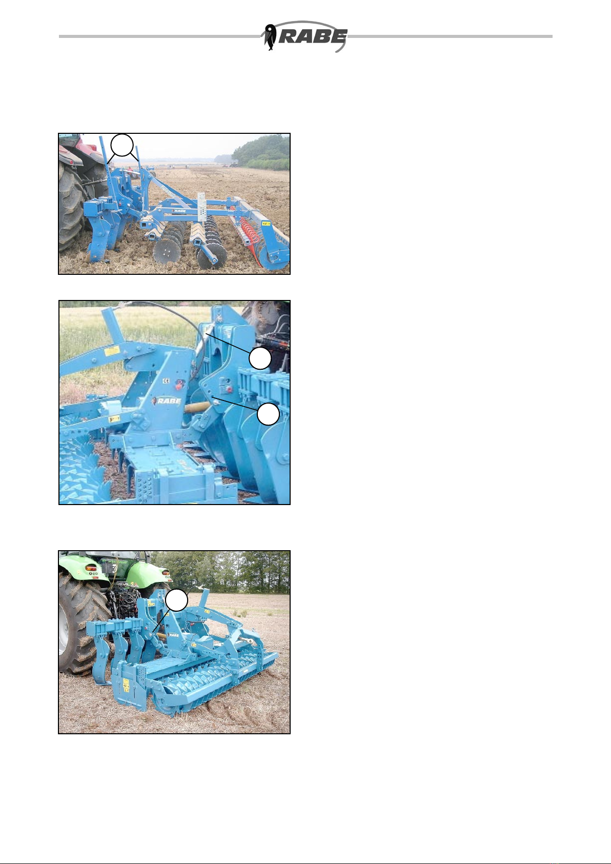
Precautions / Road transport
Prepare and check the implement for transport by
road. DO NOT stand or ride on the implement or
remain within its turning circle operating area. Ob-
serve the relevant speed limits and trafc regulati-
ons when transporting the outt by road. Take care
when negotiating curves, as towed implements
tend to swing out. Observe the road trafc regulati-
ons (StVZO or your local equivalent). These regu-
lations normally make the user responsible for the
secure hitching and safe operation on public roads
of the tractor and the implements being towed. The
attachment of towed implements must not lead to
any excess with respect to the permitted axle load,
laden weight or tyre load (depending on speed and
pressure) of the tractor. For safe steering, the front
axle of the tractor must bear at least 20 % of the
vehicle’s unladen weight.
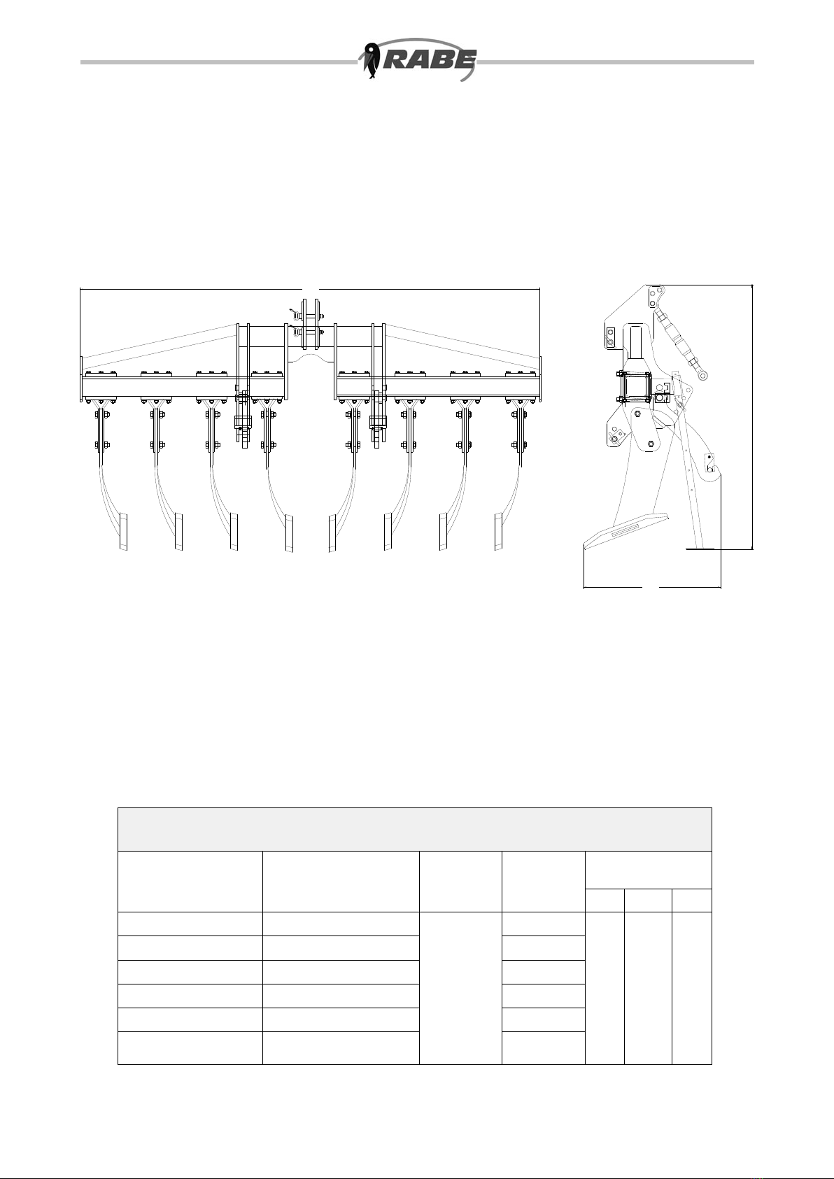
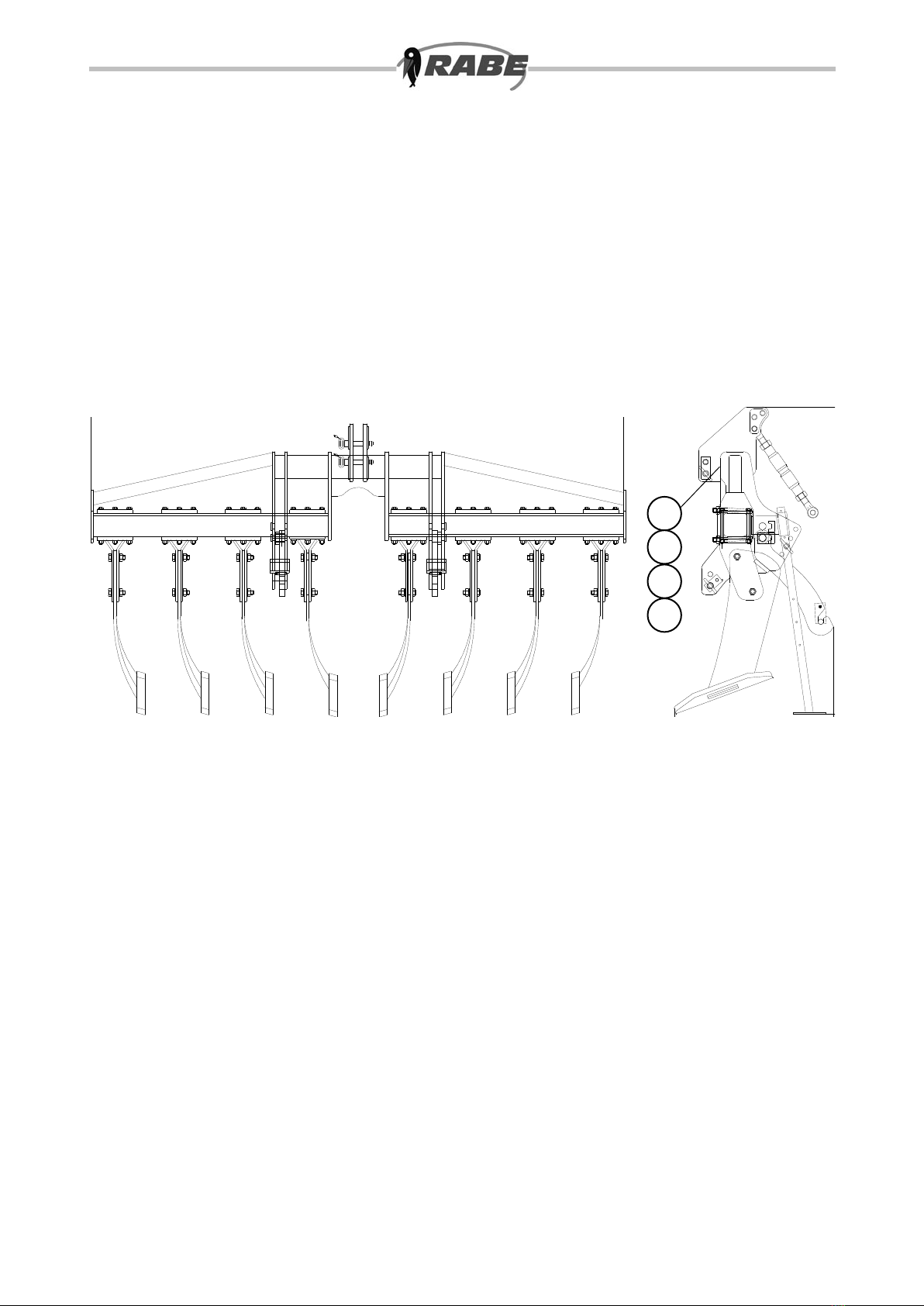
The maximum permitted width of the load is three
metres. A special permit is normally required for
moving oversized loads. In the case of front attach-
ment, the distance between the front end/ground
loosener and centre of steering wheel /tractor must
not exceed 3.5 m. If this ”front-end limit” is excee-
ded, the user must take appropriate measures to
ensure that there is adequate driver visibility at
the farmyard exit, road junctions and crossings.
This can be carried out, for example, by use of a
second person (on foot or in another vehicle) to
give the tractor driver appropriate instructions. No
avoidable overhanging item must endanger other
trafc or road users (sect. 32 StVZO or your local
equivalent). Overhanging items that cannot be
avoided must be covered and tted with warning
notices. Safety devices include appropriate lighting
and signs around all sides and the rear of the ve-
hicle and towed implement, e.g. red/white striped
warning signs measuring 423 x 423 mm. Additional
lighting is required if the towed implement blocks
those already tted to the tractor, or weather condi-
tions make it advisable: e.g. to front and rear, if the
towed implement is wider than the tractor’s lights
by more than 40 cm, or overhangs by more than 1
metre with respect to the existing rear lights.
If an additional pair of headlamps is required for
the front-mounted conguration (with only one
set of headlamps switched on at once), a special
permit is normally required.
A lighting system – with warning panels – can also
be obtained from RABE as an optional extra.
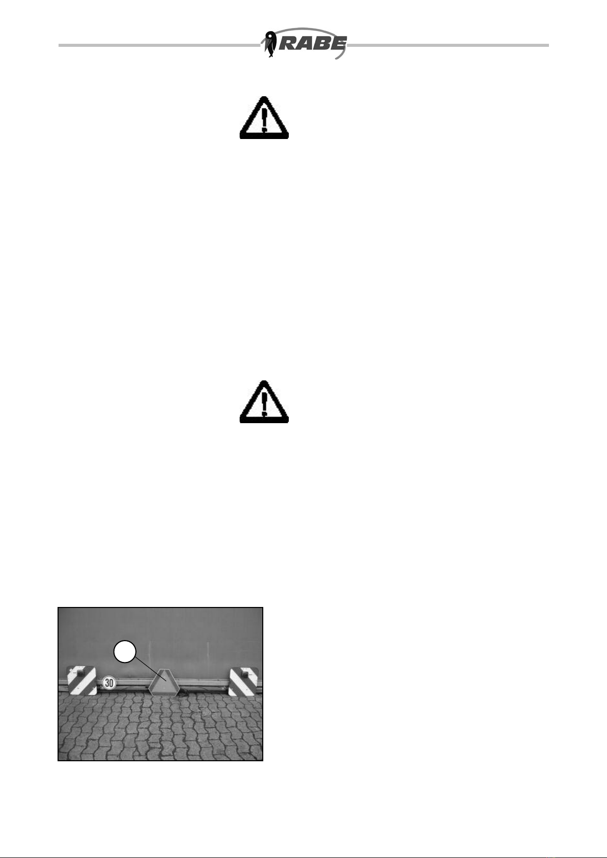
When transporting on public roads in Poland, the
warning triangle (7.1/1) must be xed to the centre
of the machine.
6
7.1
1

We reserve the right to make technical changes.
Arrangement of warning signs on the device
7
1
2
3
16
For key to symbols, see following warning signs.
This manual suits for next models
6
Table of contents
Other Rabe Farm Equipment manuals

Rabe
Rabe KORMORAN PL V 180 User manual

Rabe
Rabe COMBIBIRD CB User manual

Rabe
Rabe Aquila User manual

Rabe
Rabe Albatros Variant User manual

Rabe
Rabe KORMORAN PL V 180 User manual

Rabe
Rabe Digger HA User manual

Rabe
Rabe ADLER DS18 800 User manual

Rabe
Rabe Super Albatros 140 RMW+ User manual

Rabe
Rabe Fitis 120 M User manual

Rabe
Rabe Kormoran PF 180 User manual