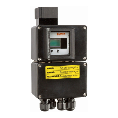
SILAS Control Unit
Type A7-3741-1110/....
Technical data subject to change without notice.
1. Safety 6
1.1 This Manual 6
1.1.1 Languages 7
1.2 Handling the Product 7
1.3 Use in Accordance with the Intended Purpose 7
1.3.1 Exclusive Purpose 7
1.3.2 Improper Use 7
1.4 Operator’s Obligations 7
1.5 Safety Instructions 8
1.5.1 General Safety Instructions 8
1.5.2 Safety Instructions for Operation 8
1.6 Standards Conformed To 9
1.7 Ex Protection Type and Certification 10
1.8 Warranty 11
2. Product Description 12
2.1 “Pressurised Enclosure” Type of Protection 12
2.2 SILAS Controller 12
2.3 Schematic Diagram of the SILAS Controller in Zone 2 13
2.4 Schematic Diagram of the SILAS Controller in Zone 22 14
2.5 SILAS Control Unit 15
2.6 Pressure Monitor 16
2.7 Digital Purge Gas Valve 16
2.8 Pressure Reducer with Pressure Gauge 17
2.9 Purge Gas Nozzle 17
2.10 Purge Gas Nozzle Zone 22 17
2.11 Mounting Kit for Internal Installation 18
3. Installation 19
3.1 Mounting Positions 19
3.2 SILAS Controller - External Mounting 20
3.2.1 Control Configuration 20
3.2.2 Installation of the Control Unit 21
3.3 SILAS Controller - Internal Mounting 22
3.3.1 Control Configuration 22
3.3.2 Mounting the Control Unit 23
3.3.3 Mounting Atmosphere Measuring Point 24
3.4 Mounting Pressure Monitor 25
3.5 Purge Gas Supply 26
3.5.1 Installation of the G1/4″ Purge Gas Supply 27
3.5.2 Mounting of the G1/2″ Purge Gas Supply 28
3.5.3 Installation of the Purge Gas Supply for Enclosures Used in Dust Explosion-Endangered Areas 29
4. Connections 30
4.1 Pneumatic Connections 30
4.2 Electrical Connections 31
4.2.1 Safety Instructions for the Electrical System 31
4.2.2 Directions for Wiring the SILAS Control Unit 31
4.2.3 Electrical Connections to the SILAS Control Unit 32
5. Operation 33
5.1 Setting of Parameters 33
5.2 “ON/OFF” Rotary Switch 33
5.3 “Parameters” Rotary Switch 33
5.4 “+”, “-“ and “SET” Buttons 34


