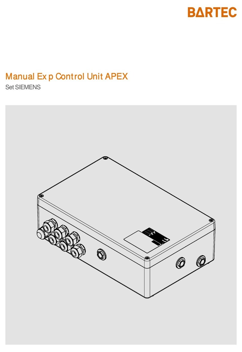
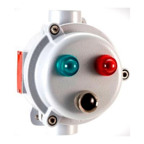
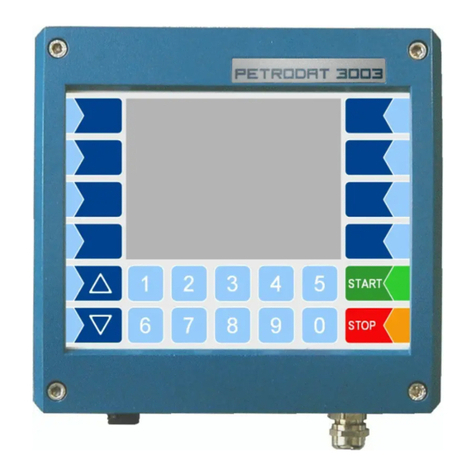
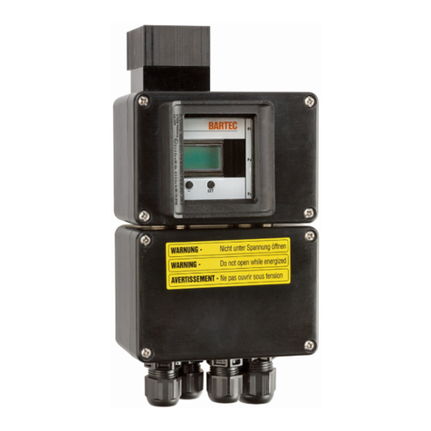
Bartec SILAS A7-3741-1110 Series User manual

Operating Instructions
SILAS Controller
A7-3741-1110/….
Version 2.00
GmbH Max-Eyth-Straße 16 Phone: 07931 597-0 E-Mail: [email protected]
Germany 97980 Bad Mergentheim Fax: 07931 597-160 Internet:http://www.bartec.de
1021284

Operating Instructions
SILAS Controller for Zones 2 and 22
Version 2.00 Page 2 of 28
SILAS_E_110806.doc Operating Instructions for the SILAS Controller •Technical data are subject to change
Table of Contents
1. System Components .................................................................................................................................. 3
2. Information on the Operating Instructions............................................................................................... 4
3. Warranty ...................................................................................................................................................... 5
4. Instructions on the Installation of the SILAS Controllers .......................................................................6
4.1 Safety Instructions ....................................................................................................................... 6
4.2 Maintenance ................................................................................................................................ 6
4.2.1 Servicing ...................................................................................................................................... 6
4.2.2 Inspection .................................................................................................................................... 6
4.3 General Data................................................................................................................................ 7
4.3.1 Installation Guidelines.................................................................................................................. 7
5. Description of the System.......................................................................................................................... 8
5.1 Use in Ex Zone 2 ......................................................................................................................... 8
5.2 Use in Ex zone 22........................................................................................................................ 9
6. Assembly................................................................................................................................................... 10
7. Technical Data for the SILAS System Components .............................................................................. 11
7.1 SILAS Controller ........................................................................................................................ 11
7.2 SILAS Pressure Control Device................................................................................................. 13
7.3 SILAS Purge Valve including Leakage Needle Valve ................................................................ 14
7.3.1 Performance Data:..................................................................................................................... 14
7.3.2 Assembly: .................................................................................................................................. 14
7.3.3 Commissioning .......................................................................................................................... 14
7.3.4 Adjustment of the Leakage Needle Valve .................................................................................. 15
7.4 Pressure Reducer ¼” and Leakage Needle Valve ..................................................................... 16
7.5 Assembly Set for the Internal Fitting of the SILAS Controller .................................................. 17
8. Circuit Diagram ......................................................................................................................................... 18
8.1 Circuit Diagram .......................................................................................................................... 18
8.2 Changing the SI 1 Fuse for the Purge Valve.............................................................................. 18
9. Parameter Settings ................................................................................................................................... 19
9.1 S 1 Rotary Switch ...................................................................................................................... 19
9.2 S 2 Rotary Switch ...................................................................................................................... 20
10. Relay Connection ..................................................................................................................................... 22
10.1 K1 Relay .................................................................................................................................... 22
10.2 K2 Relay .................................................................................................................................... 22
10.3 K3 Relay .................................................................................................................................... 22
11. Bypass Bridge........................................................................................................................................... 23
12. Purging Time Calculation ........................................................................................................................ 24
13. Malfunctioning .......................................................................................................................................... 25
14. Order Numbers ......................................................................................................................................... 28
Annex Declaration of EC Conformity

Operating Instructions
SILAS Controller for Zones 2 and 22
Version 2.00 Page 3 of 28
SILAS_E_110806.doc Operating Instructions for the SILAS Controller •Technical data are subject to change
1. System Components
The SILAS Controller of BARTEC is a controller for monitoring pressure in control panels in zone 2 and zone 22 Ex
areas. It controls the protective gas quantities for a closed control panels and accordingly generates an Ex-free area inside
the closed control panel. The dimensions of the control panel being monitored are optional thanks to the facility of using
separate control components.
SILAS Controller SILAS purge valve
SILAS pressure control device
Pressure reducer and
leakage needle valve

Operating Instructions
SILAS Controller for Zones 2 and 22
Version 2.00 Page 4 of 28
SILAS_E_110806.doc Operating Instructions for the SILAS Controller •Technical data are subject to change
2. Information on the Operating Instructions
The product described in this manual has been tested and left the factory in a perfect condition as regards meeting safety
requirements. To ensure that this product operates perfectly and safely, it may only be used in the way described by the
manufacturer. Appropriate transportation, suitable storage, and careful operation are also essential for the perfect and safe
operation of this product.
This manual contains the information necessary for using the SILAS Controller in accordance with the intended
purpose. It is addressed to technically qualified personnel.
Familiarity with and the technically perfect implementation of the safety instructions and warnings described in this manual
are preconditions for safe installation and commissioning. The safety notes and warnings given in this documentation are
given in a general way and only qualified personnel will have the necessary specialised know-how to interpret and
implement them correctly in specific cases.
This manual is an integral part of the scope of supply even if it can be ordered and/or delivered separately for reasons of
logistics. If you need any further Information, please ask the BARTEC branch that is near you or responsible for your area.
The safe and perfect assembly of the SILAS Controller on the pressurised control panel is essential for a perfect and
correct mode of operation.

Operating Instructions
SILAS Controller for Zones 2 and 22
Version 2.00 Page 5 of 28
SILAS_E_110806.doc Operating Instructions for the SILAS Controller •Technical data are subject to change
3. Warranty
As a basic rule, our “General Conditions of Sale and Delivery” apply. These are available to the owner-operator at the latest
when the contract is concluded. Warranty and liability claims for personal injury and damage to property are excluded if they
are due to one or more of the following reasons:
•Inappropriate assembly, commissioning, operation and maintenance of the SILAS Controller.
•Operating the SILAS Controller with defective safety devices or safety devices that have not been
affixed correctly or do not function properly (e.g.: bridged fuses).
•Non-compliance with the instructions in this manual with respect to transport, storage, assembly,
commissioning, operation, maintenance.
•Catastrophic instances due to effects of foreign matter and force majeure.
We guarantee the SILAS Controller and its accessories for a period of 1 year as of the date of delivery from the Bad
Mergentheim factory. This warranty covers all parts of the delivery and is restricted to the replacement free of charge or the
repair of the defective parts in our Bad Mergentheim factory. For this purpose the packaging of the delivery must be kept as
far as possible.
In the event of such a claim, the goods must be returned to us after written prior arrangement. The customer shall not have
a claim for repairs at the site of installation.

Operating Instructions
SILAS Controller for Zones 2 and 22
Version 2.00 Page 6 of 28
SILAS_E_110806.doc Operating Instructions for the SILAS Controller •Technical data are subject to change
4. Instructions on the Installation of the SILAS Controllers
4.1 Safety Instructions
For electrical installations the relevant installation and operation regulations must be followed! (e.g. Directive 1999/92/EC,
Directive 94/9EC, German Ordinance on Industrial Safety and Health (BetrSichV) and the national regulations that are in
force, IEC/EN 60 079-14 and VDE 0100).
The owner-operator of an electrical system in a potentially explosive area must maintain the resources in a proper condition,
operate them correctly, monitor them and carry out maintenance and repair work in accordance with the German Ordinance
on Industrial Safety and Health (BetrSichV) and national regulations and EN 60 079-14).
The unit may be opened only in the manufacturer’s works!
The unit is factory sealed! Do not open!
4.2 Maintenance
When doing maintenance work or servicing and when checking associated equipment, adhere to the valid regulations in
accordance with Directive 1999/92/EC, IEC 60079-19 and EN60079-17 a !
Installation/dismantling, operation and maintenance work may only be carried out by trained specialists. Statutory
regulations and other binding directives on workplace safety, accident prevention and environmental protection must be
adhered to.
Observe the national waste disposal regulations when disposing of the equipment.
4.2.1 Servicing
Regular servicing is not necessary if the equipment is operated correctly in accordance with the installation instructions and
environmental conditions.
4.2.2 Inspection
In accordance with IEC 60079-19 and EN 60079-17, the owner-operator of the electrical installations in potentially explosive
areas has an obligation to have these installations checked by a qualified electrician to ensure that they are in a proper
condition.

Operating Instructions
SILAS Controller for Zones 2 and 22
Version 2.00 Page 7 of 28
SILAS_E_110806.doc Operating Instructions for the SILAS Controller •Technical data are subject to change
4.3 General Data
•• The user is merely permitted to carry out the necessary wiring work on the terminals accessible to him.
Any further dismantling may only be done by the manufacturer or by persons authorised by the
manufacturer. The unit is factory sealed. Do not open!
•• The Ex e terminal chamber with terminals for supply voltage and a data line may only be opened if it has
been ensured that the atmosphere is not potentially explosive and no voltage is applied.
•If the atmosphere is potentially explosive, the unit may not be operated until it has been ensured that the
enclosure is completely sealed and all screws have been tightened.
.
4.3.1 Installation Guidelines
■The potential equalisation connection must be connected to the equipotential bounding
conductor in the potentially explosive area. As the intrinsically safe circuits are galvanically
connected to earth, there must be compensation for potential electrical charges over the
entire course of the installation of the intrinsically safe circuits.
■The safety and accident prevention regulations applicable to the respective use must be
observed.
■The equipment must be installed first before it may be operated.
■It must be possible to de-energise the products at any time (in fixed installations by means of
an all-pole mains disconnecting switch or fuse);.
■It must be ensured that the supply voltage agrees with the specifications in the manual and
that the tolerances are adhered to.
■Malfunctioning cannot be ruled out if values either exceed or fall short of the specified
tolerances.
■EMERGENCY STOP equipment must remain effective in all modes and states of operation.

Operating Instructions
SILAS Controller for Zones 2 and 22
Version 2.00 Page 8 of 28
SILAS_E_110806.doc Operating Instructions for the SILAS Controller •Technical data are subject to change
5. Description of the System
The SILAS Controller can be used in combination with the pressure control device and the digital purge valve for all
normal applications (control panels, control enclosures, printers, operator terminals etc.) in Ex zone 2 and Ex zone 22.
5.1 Use in Ex Zone 2
The user decides on his own responsibility about the use of a purging cycle. However he must be absolutely certain before
switching on the overpressure-monitored control panelthat there are no more potentially explosive gas mixtures inside the
control panel or that the gas concentration is less than 25% of the lower explosion limit of gases. This can be ensured either
by manually measuring the gas concentration using suitable measuring apparatus or by means of a SILAS Controller
monitored purging cycle for the automatically monitored dilution of the gas mixtures.
After assembling the SILAS Controller, the pressure control device and the purge valve on the enclosure and after
connecting the mains voltage and purge gas, the system starts automatically. The system then regulates and monitors the
purge gas flow rate and the enclosure’s internal pressure during the purging cycle and the enclosure’s internal pressure
during the operating phase.
If the minimum pressure “P 1” in the panel is exceeded during the purging cycle, the SILAS Controller connects the
purging-air nozzle in the input valve. If the pressure and accordingly the flow at the pressure control device module
(switching value of “P 3”) is sufficient, the preset remaining purging time counts down to zero. At the end of the pre-purging
time the purging-air nozzle closes and the leakage losses of the overpressure-monitored control panel are compensated by
means of the needle valve inside the purge valve.
The following functions are assigned to the various pressure switch values:
P1: “MIN” disconnection threshold: when the pressure falls below this value, an alarm is activated.
P2: Pre-alarm: when the pressure falls short of this pressure value, a pre-alarm is activated.
P3: Purging pressure: when the pressure exceeds this pressure value, a purging time is activated.
P4: “MAX” disconnection threshold: when this pressure value is exceeded, the alarm is activated.
When the purge pressure falls below the value of "P 3", the purge time circle stopped after the time setting of "Delay" and
the purge time counter will be set to the complete purge time.
To prevent the internal pressure reaching an excessively high value as a result of an impermissibly high flow resistance
at the pressure control device for the internal pressure, the purging pressure can be limited during the pre-purging time to
the “P 4” value (PRG Y3 programming, see chapter on Settings). When a digital valve is used, the purging-air nozzle will
switch off for a short time on reaching “P4” (overpressure control).

Operating Instructions
SILAS Controller for Zones 2 and 22
Version 2.00 Page 9 of 28
SILAS_E_110806.doc Operating Instructions for the SILAS Controller •Technical data are subject to change
After the end of the purging time, the operating phase is initiated by the following measures:
•The purge valve closes and the leakage losses are compensated by means of the integrated leakage air
valve.
•The “K 2” LED lights up.
•The K 2 relay energises. K 3 Relay switches depending on the configuration.
•The remaining purging display goes out and the pressure inside the enclosure is displayed.
If the internal pressure during the operating phase drops below the switching „P 2” value, e.g.: due to increased leakages
during the operation, K1 relay connects the purging-air nozzle for a short time.
If the internal pressure during the operating phase drops below the switching value of “P 1”, e.g.: due to the doors being
opened, the K 3 relay energises with about 5 sec. time delay and in this way signalises that there is a drop in pressure. At
the same time, the purging-air nozzle in the purge valves is switched off to prevent purge gas flowing in when the door is
opened. If the door is closed and the internal pressure rises above the value of “P1”, the purging-air nozzle closes again
until the internal pressure reaches the “P 2” value.
If the internal pressure during the operating phase exceeds the ”P 4” switching value, the K 2 relay switches off for the
duration of the increased overpressure.
5.2 Use in Ex zone 22
In applications in the Ex zone 22 it is essential to clean the control panel inside thoroughly in order to remove dust deposits
before the overpressure-monitored control panel is switched on for the first time. A pre-purging cycle functioning in the same
way as for the application in zone 2 is not suitable for this purpose.
During the operating phase the penetration of dust is prevented by the constant overpressure with relation to the ambient
atmosphere. The internal pressure is monitored by the SILAS Controller's pressure control.
To produce overpressure in the control panel greater than the switching value of “P 1”, the pressure reducer with connected
leakage needle valve is connected directly to the control panel. To prevent overpressure greater than the permissible “P 4”
switching value, the type 17-51P3-1604 pressure control device is used as an overpressure control device.
The system starts automatically once the SILAS Controller, the pressure control device and the purge valve have been
assembled at the control panel and the mains voltage and purge gas have been connected. The system then monitors the
enclosure’s internal pressure during the operating phase.
If the internal pressure inside the control panel rises above the switching value of “P 1”, the K 2 relay energises.
If the internal pressure during the operating phase drops below the switching value of “P 1”, e.g.: when the door is opened,
K 2 relay switches with approx. 5 sec. time delay. If the internal pressure during the operating phase exceeds the “P 4”
switching value, the K 2 relay switches off for the duration of the increased overpressure.

Operating Instructions
SILAS Controller for Zones 2 and 22
Version 2.00 Page 10 of 28
SILAS_E_110806.doc Operating Instructions for the SILAS Controller •Technical data are subject to change
Druckwächter-Modul17-51P3
BARTEC
oder
oder
BARTEC
Druckwächter-Modul17-51P3
6. Assembly
The system configuration makes assembly at the control panel easy. For this purpose the SILAS Controller is mounted
on the outside of the control panel. The internal pressure is monitored via a 13-mm through hole and sealed by means of
the bulkhead screw connection. Twisting is prevented by 2x M4 screws. The possible assembly position is shown in the
drawing below. It is also possible to fit into the pressurised control panel. This is reached by simply removing the upper flow
adapter and assembling the SILAS Controller on an inner mounting plate in the control panel. An M5 internal thread is
available for connecting the reference pressure. With the assembly set type 05-0091-0117 (optional) a connection is
produced between the reference pressure and the surrounding atmosphere.
A through hole of 37 mm is required to mount the pressure control module. The outlet screw connection or in the event of
outside assembly the lower inlet screw connection are used for mounting. Both screw connections are identical and
interchangeable. Note: when fitting the pressure control module, take account of the flow direction as otherwise the control
panel could be damaged by excessive internal pressure.
To mount the purge valve, a through hole of 17mm is required. The valve can be mounted inside or outside the control
panel. Various pressure reducers which can be connected upstream are available as options with all the necessary
connecting fittings.
Mounting the pressure control device and purge valve in the following position will ensure ideal and thorough purging.

Operating Instructions
SILAS Controller for Zones 2 and 22
Version 2.00 Page 11 of 28
SILAS_E_110806.doc Operating Instructions for the SILAS Controller •Technical data are subject to change
7. Technical Data for the SILAS System Components
7.1 SILAS Controller
Types : A7-3741-1..0/....
Marking : II 3G Ex nAC [pz] II T4 -20 °C ≤Ta≤+ 60 °C
II 3G Ex nAC [pz] II T6 -20 °C ≤Ta≤+ 40 °C
II 3D Ex tD A22 [pD] IP 54 T 85°C -20 °C ≤Ta≤
+ 60 °C
Supply voltage : AC 230 V ± 10 %, 48-62 Hz or
AC 115 V ± 10 %, 48-62 Hz or
DC 24 V ± 10 %
Max. power consumption Pmax : 8 W
K 2 relay and K3 : up to the maximum Tambient 40°C: maximum AC 253 V; 5 A, cos phi 0.7
: up to the maximum Tambient 60°C: maximum AC 253 V; 0.5 A, cos phi 0.7
K1 relay : up to the maximum Tambient 60°C: maximum AC 253 V; 0.5 A, cos phi 0.7
Permissible ambient temperatures : Storage -20 °C to +60 °C
Operation -20 °C to +40 °C (+60 °C)
Pressure range : 0-25 mbar for all pressure switch values
Purging time : settable 0...60 minutes
Connecting terminals : maximum 2.5 mm²
Weight : 1.2 kg
Protection class : IP 65

Operating Instructions
SILAS Controller for Zones 2 and 22
Version 2.00 Page 12 of 28
SILAS_E_110806.doc Operating Instructions for the SILAS Controller •Technical data are subject to change
Dimensions and Fastening Drill Holes
Included in the scope of supply:
1a: SILAS controller
1b: Bulkhead screw connection R1/4" x R1/8"
1c: Sealing brass dia. 13mm
1d: Sealing polyamide dia. 13mm

Operating Instructions
SILAS Controller for Zones 2 and 22
Version 2.00 Page 13 of 28
SILAS_E_110806.doc Operating Instructions for the SILAS Controller •Technical data are subject to change
56
Silas Druckwächter
Typ 17-51P3-1604
BARTEC
70 55
Spark resistor
O-Ring 40 x 2mm
Purge gas
Inside
wall of cabinet
1 hole ø 37 mm
Purge gas
7.2 SILAS Pressure Control Device
Type : 17-51P3-1604
Dimensions : 55 x 70 x 56 mm
Opening pressure : 5 mbar
Control panel borehole : 37 mm
Weight : approx. 0.2 kg
Dimensions for the SILAS pressure control device

Operating Instructions
SILAS Controller for Zones 2 and 22
Version 2.00 Page 14 of 28
SILAS_E_110806.doc Operating Instructions for the SILAS Controller •Technical data are subject to change
7.3 SILAS Purge Valve including Leakage Needle Valve
Type : 03-5110-0026 mains voltage AC 230 V
: 03-5100-0028 mains voltage AC 115 V
: 03-5110-0029 mains voltage DC 24 V
Dimensions : 90 x 60 x 96 mm
Min. input pressure : 1.5 bar
Control panel borehole : 17 mm
Weight : approx. 1.2 kg
7.3.1 Performance Data:
Before assembling the SILAS purge valve, it is essential to check if the selected valve model’s operating pressure, supply
voltage and supply frequency agree with the required values. For this purpose, check the technical data documented on the
solenoid valve.
7.3.2 Assembly:
Remove any covers. Assemble the SILAS purge valve so that the arrow points in the direction of flow of the purge gas,
whereby no assembly foreign matter may be allowed to penetrate the valve. On both sides the purge valve is provided with
an internal thread of R 3/8“. The purging-air nozzle has been screwed in already in the factory. The purge valve is fastened
with the enclosed bulkhead screw connection R 3/8“ x ¼“ directly at the enclosure. As a general rule, the purge valve can be
mounted in any position but a vertical position is preferable as it prevents the penetration of tiny particles into the inner
armature pipe.
Maximum ambient temperature
The SILAS purge valve was marked in the factory with a maximum surface temperature at a maximum
ambient temperature. The self-heating of the SILAS purge valves may therefore not be increased by
mounting onto other sources of heat.
7.3.3 Commissioning
The purge valve is connected to the SILAS Controller; terminals 6,11 and 13. After connecting the SILAS
Controller's mains voltage and selecting the PRG Y_ parameter assignment, the purging-air nozzle is connected during
the pre-purging time. After the pre-purging time the purge valve closes, the leakage losses in the enclosure are
compensated by the settable leakage needle valve.
Note: if the enclosure pressure drops below the P2 value, the purging-air nozzle opens for a short time to compensate for
the increase in leakage losses.

Operating Instructions
SILAS Controller for Zones 2 and 22
Version 2.00 Page 15 of 28
SILAS_E_110806.doc Operating Instructions for the SILAS Controller •Technical data are subject to change
7.3.4 Adjustment of the Leakage Needle Valve
The leakage needle valve integrated in the purge valve can be adjusted at any time to the quantity required to compensate
for the leakage losses. The factory setting is: 15 l/min., at 2 bar input pressure.
To alter the leakage air quantity, the adjusting screw which is accessible through the purging-air nozzle must first be closed
in a clockwise direction with the aid of a suitable screwdriver.
Then the necessary leakage air quantity is adjusted by turning to the required value.
The curve given in the table shows the passage of the air leakage quantity depending on the turns.
After completing the adjustment, the enclosure’s overpressure during operation should be between 2 and 3 mbar.
Dimensions SILAS Purge Valve
0
0,5
1,0
1,5
2,0
2,5
3,0
3,5
4,0
4,5
5,0
0 1020304050 60 70 80 90 100
Rotation
Pre pressure at the purge
valve during operate
Leackage flow rate [ l/min]
Purge nozzle
maximal wide: 2 mm
Leackage nozzle with
sound absorber
95
903m 60

Operating Instructions
SILAS Controller for Zones 2 and 22
Version 2.00 Page 16 of 28
SILAS_E_110806.doc Operating Instructions for the SILAS Controller •Technical data are subject to change
7.4 Pressure Reducer ¼” with Leakage Needle Valve
Pressure reducer ¼” with Leakage
needle valve
: 05-0056-0015
Control panel borehole : 17 mm
Maximum input pressure : 25 bar
Adjustable initial pressure : 0-6 bar
Material : Enclosure: zinc die-casting; sealing: NBR
Weight pressure reducer 1/8” : 0.3 kg
Weight leakage needle valve : 0.05 kg
44
3,0
0
2,5
2,0
1,5
1,0
0,5
0
5,0
4,5
4,0
3,5
402010 30 50 7060 80 10090
Rotary
Pre pressure
rate of leacka
g
e
[
l/min
]
45
115
3b
3a
2b
2a
Cabinet
2a: pressure reducer
2b: detachable connection
3a: leakage needle valve
3b: reducer adapter

Operating Instructions
SILAS Controller for Zones 2 and 22
Version 2.00 Page 17 of 28
SILAS_E_110806.doc Operating Instructions for the SILAS Controller •Technical data are subject to change
7.5 Assembly Set for the Internal Fitting of the SILAS Controller
The assemblöy set will be used when the SILAS-Controller has to be mounted inside the Ex pz panel. In this
case the conection for the referenz of the atmosphaerepressure has to be directed with a tube to the outside.
Type : 05-0091-0117
Component parts : 1 connection for the SILAS output M 5 x hose 4 mm
1 atmosphere connection R 1/8” x hose 4 mm
2 m hose 4 mm
1 set of assembly instructions
4a:
Flow connector section A
4b:
Hose connection
4c-4f:
Atmosphere connection
4g:
Hose 4 mm
4h:
Ex pz enclosure

Operating Instructions
SILAS Controller for Zones 2 and 22
Version 2.00 Page 18 of 28
SILAS_E_110806.doc Operating Instructions for the SILAS Controller •Technical data are subject to change
8. Circuit Diagram
8.1 Circuit Diagram
8.2 Changing the SI 1 Fuse for the Purge Valve
The SILAS Controller's junction box has a fuse holder for a 5 x 20 mm fuse. This fuse serves to protect a digital purge
valve connected to the terminals 6,10 and 13. The fuse rating may not exceed the value of 3 x INominal of the valve’s nominal
current.
Observe the following when changing:
- Disconnect from voltage supply before changing the integrated SI 1 valve fuse.
Factory-fitted fuse values: mains voltage AC 230 V / 80 mA; AC 115 V / 160 mA; DC 24 V / 500 mA
13
NL +
78910 11
PE
12
µ-Controller
645
SI 1
K 1
LED 1
K 2
LED 2
Alarm
231
K 3
LED 3
Parameter
SET ON/OFF
Yellow Green Yellow
Power
supply
Purge valve Operate

Operating Instructions
SILAS Controller for Zones 2 and 22
Version 2.00 Page 19 of 28
SILAS_E_110806.doc Operating Instructions for the SILAS Controller •Technical data are subject to change
9. Parameter Settings
The S 1 rotary switch switches the SILAS Controller on. The parameter display is selected by turning the S 2 rotary
switch.
The setting parameters are changed with the “+” and “-“ keys. They are saved by pressing the “SET” key. The saved value
is marked by a “*”.
The switching states of the K1, K 2 and K 3 relays are displayed by means of LEDs K 1, K 2 and K 3, whereby the LEDs
light up when the respective relay has picked up.
9.1 S 1 Rotary Switch
When the S1 rotary switch is at pos. 1, the SILAS Controller is switched on. If the SILAS Controller is switched
off, the last displayed value remains in the display. The K1 to K3 relays switch off.
S 1 rotary switch
S 2 rotary switch
Status LED for K1, K2 und K3 relays
Bypass connection
(S 2 switch at pos. 9)

Operating Instructions
SILAS Controller for Zones 2 and 22
Version 2.00 Page 20 of 28
SILAS_E_110806.doc Operating Instructions for the SILAS Controller •Technical data are subject to change
9.2 S 2 Rotary Switch
The following functions are assigned to the respective position of the S 2 rotary switch:
Aktion
Position Function Display
Purge time is
needed
Purge time
started, if P1
is reached
Purge time
stopped, if
P4 is
reached
K2 switch
off, if the
pressure
falls below
the value of
P1
PRG YES YES NO NO NO
PRG YP1 YES YES NO NO
PRG YP2 YES YES NO YES
PRG YP3 YES YES YES NO
1 Pre-purge function
PRG NO NO NO NO NO
2 Pre-purging time
(min: sec) P T Pre-purging time if a pre-purging cycle PRG Y _ is activated
3 Pressure value P 1
(mbar) P 1 “MIN” disconnection threshold
4 Pressure value P 2
(mbar) P 2
a) Pre-alarm
b) If a purge valve is connected, the purge valve switches
the purging-air nozzle on briefly if the value falls short of
P 2 during operation.
5 Pressure value P 3
(mbar) P 3 Pressure value at which the purging time counts down if the
zone 2 function is selected.
6 Pressure value P 4
(mbar) P 4
“MAX” disconnection threshold. When the “P 4” is reached, K
2 relay switches off for the duration of the increased
overpressure.
Other manuals for SILAS A7-3741-1110 Series
1
This manual suits for next models
3
Table of contents
Other Bartec Controllers manuals