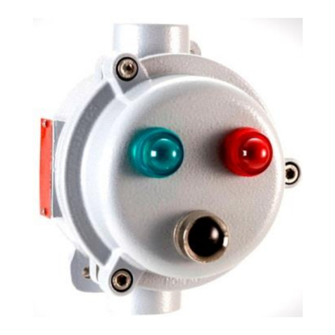
Bartec 07-3400 Series Quick start guide

Technical data subject to change without notice 01-3400-7D0001/REV-A-12-2022/ESS-4619261/8
BARTEC Operational Instructions – Control and signal device actuators and accessories
Control and signal device actuators
and accessories
Type 07-3400-****/****

Technical data subject to change without notice 01-3400-7D0001/REV-A-12-2022/ESS-4619262/8
BARTEC Operational Instructions – Control and signal device actuators and accessories
Note on instructions
When working in hazardous areas, the safety of personnel,
environment and equipment depends on compliance with the
relevant safety regulations. The people in charge of installation
and maintenance bear a special responsibility. It is essential
that they have an exact knowledge of the applicable rules and
regulations.
The instructions provide a summary of the most important
safety measures and must be read by every one working with the
product so that they will be familiar with the correct handling of
the product.
The instructions have to be kept for future reference and must
be available throughout the expected life of the product.
Description
For the ComEx modules type 07-33**-****/**** there are a
large number of control and signal device actuator are available
in different versions. All control and signal device actuator are
made of high-quality thermoplastic and can be used in almost
all potentially explosive areas.
The Control and signal design devices enables easy and safe
mounting and can be complemented by useful accessories.The
components are developed and certified for global hazardous
areas.
Control and signal device actuators and accessories
Type 07-3400-****/****
Explosion protection
Technical data
Notified Body Number 0044
Approved Body Number 2503
ATEX/UKEX
Ex protection type
II 2G Ex eb IIC Gb
II 2D Ex tb IIIC Db
ATEX/UKEX
Certification
CML21 ATEX31132U
CML22 UKEX3332U
IECEx
Ex type of protection
Ex eb IIC Gb
Ex tb IIIC Db
IECEx certificate
number
IECEx CML 21.0128U
CEC (UL Mark) Ex eb IIC Gb
Ex tb IIIC Db
Class I, Division 2, Groups A, B, C, D
Class II, Division 2, Groups F, G
Class III, Division 2
CEC (UL Mark) Class I, Zone 1, AEx eb IIC Gb
Zone 21, AEx tb IIIC Db
Class I, Division 2, Groups A, B, C, D
Class II, Division 2, Groups F, G
Class III, Division 2
UL certifacte number UL E184198
Operating temperature -40 °C to +70 °C (-40 °F to +158 °F)
Service temperature -55 °C to +70 °C (-67 °F to +158 °F)
(related to explosion protection
acc. to EN IEC 60079-0)
For further approvals and certificates, see www.bartec.com
Degree of protection Up to IP67 acc. to EN 60529 and NEMA 4X
acc. to UL 50E. Requires correct installation
in in a mounting hole on an enclosure with
appropriate degree of protection.
Mounting –Installation in enclosures with a wall
thickness of 1mm to 6 mm (0.04 in to 0.24 in)
–Suitable for through-holes 30.3 mm (1.19 in)
–Torque fixing nut 2.8 to 3.4 Nm
Mechanical risk level High
Dimensions See selection chart on page 3
Weight See selection chart on page 3

Technical data subject to change without notice 01-3400-7D0001/REV-A-12-2022/ESS-4619263 / 8
BARTEC Operational Instructions – Control and signal device actuators and accessories
Safety Instructions
The control and signal device actuators may be used only within
the specified service and operating temperature.
Utilisation in areas other than those specified and the
modification of the product by any one other than the
manufacturer is not permitted and will exempt BARTEC from
liability for defects and any further liability .
Incorrect installation can cause malfunctioning and the loss of
explosion protection
Only service technicians who are authorized to work in
potentially explosive atmospheres may do any of the assembly,
disassembly, installation, commissioning, maintenance, and
fault clearance work.
The generally applicable statutory rules and other binding
directives relating to workplace safety, accident prevention and
environmental protection must be observed.
When setting up or operating explosion-resistant electrical
systems, IEC/EN 60079-14 and all relevant installation and
operating regulations must be observed.
The control and signal device actuators may be used only if it
is in a clean and undamaged condition. It is not permissible to
modify the actuators in any way.
Marking
Particularly important points in these instructions are marked
with a symbol:
DANGER
indicates a hazardous situation which, if not avoided, will
result in death or serious injury.
WARNING
indicates a hazardous situation which, if not avoided, could
result in death or serious injury.
CAUTION
indicates a hazardous situation which, if not avoided, could
result in minor or moderate injury.
NOTICE
is used to address practices not related to personal injury.
NOTE
Important instructions and information on effective,
economical and environmentally compatible handling.
Standards conformed to
Please see the Attestation of Conformity.
Transport, Storage
NOTICE
Control and signal device actuators damage through
incorrect transport or incorrect storage.
• Transport and storage is permissible in original packaging
only.
• Store the control and signal device actuators in a dry place.
Assembly and Commissioning
WARNING
Risk of injury due to incorrect proceedings.
• Only authorized and qualified personnel may do any of the
assembly, disassembly, installation and commissioning
work.
• Use suitable tools.
Assembly/Disassembly
NOTICE
Damage to control and signal device actuators due to
incorrect installation dimensions.
• The minimum spacing between the mounting holes must be
observed.
NOTE
Installation dimensions and assembly drawings, see page 5.
Commissioning
Before commissioning, check that:
– The device has been installed correctly.
– The device is not damaged.
Installation
The control and signal device actuators must be installed as
a stationary unit. The following schedule of limitation must be
observed:
– When the components are installed to electrical equipment,
the service temperature of the components of -55 °C to
+70 °C (-67 °F to +158 °F) must not be exceeded.
– The control and signal device actuators, type 07-3400-
A***/**** (push button), and type 07-3400-P***/****
(mushroom push button), must only be used in combination
with the ComEx switch module type 07-332*-****/**** or
type 07-3382-****/****.

Technical data subject to change without notice 01-3400-7D0001/REV-A-12-2022/ESS-4619264 / 8
BARTEC Operational Instructions – Control and signal device actuators and accessories
– To confirm with IEC 60947-5-5 & UL 60947-5-5 the E-stop
twist and pull to release actuators 07-3400-R***/**** &
07-3400-N***/****, have to be used in combination with the
ComEx Modules. (combinations of E-stop twist with 4-pole
ComEx switch module type 07-3382-* 1xNC/3xNO & 4xNO
is not allowed. In addition, a yellow background is required,
which can be created using the BARTEC background sticker
05-2144-1097 or protective collar 05-0032-0019.
– In the case of the pushbutton type 07-3400-A* and double
pushbutton 07-3400-C*, it is absoluty necessary to attach an
enclosed colored label.
Maintenance and Fault Clearance
WARNING
Risk of injury due to incorrect proceedings.
• Only authorized qualified personnel may do any of the work
relating to maintenance and fault clearance.
• IEC/EN 60079-17 and all relevant installation and operating
regulations must be observed.
It is recommended to formulate a maintenance plan according
to standards.
Maintenance
WARNING
Risk of serious accidents due to damaged parts.
• Check actuators regularly for cracks and damage. Make
sure that they are properly established.
NOTICE
Damage to actuators due to incorrect cleaning.
• It is not allowed to clean control and signal device actuators
with compressed air.
The operator of the control and signal device actuators must
keep it in good condition, operate it properly, monitor it and clean
it regularly.
The owner/managing operator must schedule maintenance
intervals which will suit the respective conditions of use.
Fault Clearance
WARNING
Risk of serious injury due to use of non-original spare parts.
• Use original parts only as replacements.
The control and signal device actuators are defective if it no
longer actuates the attached command equipment or if the
illuminated disc becomes damaged. Defective actuators cannot
be repaired.
Defective control and signal device actuators can be taken
off and replaced by functioning actuators of the same type
considering this operational instruction.
Disposal
NOTE
Environmental damage can be caused by incorrect waste
disposal. When in doubt, local authorities or specialist disposal
companies can provide information on environmentally
friendly disposal.
The components in the switch module contain metal and plastic
parts. Therefore the statutory requirements for disposing of
electronic scrap must be observed.
Service-Address
BARTEC GmbH
Max-Eyth-Str. 16
97980 Bad Mergentheim
Germany
Phone: +49 7931 597-0
info@bartec.com

Technical data subject to change without notice 01-3400-7D0001/REV-A-12-2022/ESS-4619265 / 8
BARTEC Operational Instructions – Control and signal device actuators and accessories
Mounting of the actuators
Assembly of Functional Modules with Bayonet Fixing
Installation Dimensions
1shield holder
2Control and signal device actuator
3Enclosure with wall thickness of 1 to 6 mm (0.04 to
0.24 in) with a mounting hole 30.3+0.3 mm (1.2+0.01 in)
4Fixing nut, must be tight a torque of 2.8 - 3.4 Nm
(2 - 2.5 lb.ft)
5Torquing tool
The control and signal device actuators may optionally be
provided with one of the following accessories:
- protective collar
- locking device
- shield holder
- marking clip
- printed labels
1Control and signal device actuator
2ComEx module type 07-33**-****/****
mm in
A75 2.95
B16.5+0.2 0.65+0.008
CØ30.3+0.3 Ø1.2+0.01
D3+0.1 0.12+0.004
E40 1.6
Mounting hole with cut-out for anti-twist protection, typical
position: top (12 o’clock position).
Minimum spacing for the mounting boreholes:
– horizontal 40 mm (1.6 in)
– vertical 70 mm (2.8 in)
Chamfer or rounding from 0.1 mm up to 0.3 mm
(0.004 up to 0.01 in) on outer surface of hole is required.
A
D
B
C
E
12
1 2 43 5

Technical data subject to change without notice 01-3400-7D0001/REV-A-12-2022/ESS-4619266 / 8
BARTEC Operational Instructions – Control and signal device actuators and accessories
When mounting, first hook the marking clip/
shield holder into the attachment from above
on the marked side and then latch it into place
by pressing it into the opposite side. Note the
position relative to the anti-rotation device.
Marking clip/Shield holder
Attach the holding frame of the locking device
to the application housing from above. Note the
position relative to the anti rotation protection.
Locking device
Push the protective collar onto the application
housing from below. Note the position relative to
the anti rotation protection.
Protective collar
Start of
installation
Position of
the anti-twist
protection
Optional:
Attachment of the latch
with ball chain. Thread
the ball chain through and
close the clamp closure
Mounting information

Technical data subject to change without notice 01-3400-7D0001/REV-A-12-2022/ESS-4619267 / 8
BARTEC Operational Instructions – Control and signal device actuators and accessories
Konformitätsbescheinigung
Attestation of Conformity
Attestation de conformité
No01-3400-7C0001
FB-0171g
Seite / page / page 1von / of / de 1
Wir
We
Nous
BARTEC GmbH
Max-Eyth-Straße 16
97980 Bad Mergentheim
Germany
erklären in alleiniger
Verantwortung, dass das Produkt
declare under our sole
responsibility that the product
attestons sous notre seule
responsabilité que le produit
Betätigungsvorsätze
Control and signal
device actuators
Tètes de commande
Typ 07-3400-****/****
auf das sich diese Erklärung
bezieht den Anforderungen der folgen-
den Richtlinien (RL) entspricht
to which this declaration relates is in
accordance with the provision of the
following directives (D)
se référant à cette attestation
correspond aux dispositions des direc-
tives (D) suivantes
ATEX-Richtlinie 2014/34/EU
ATEX-Directive 2014/34/EU
Directive ATEX 2014/34/UE
RoHS-Richtlinie 2011/65/EU
RoHS-Directive 2011/65/EU
Directive RoHS 2011/65/UE
und mit folgenden Normen oder nor-
mativen Dokumenten
übereinstimmt
and is in conformity with the
following standards or other
normative documents
et est conforme aux normes ou docu-
ments normatifs ci-dessous
EN IEC 60079-0:2018
EN IEC 60079-7:2015/A1:2018
EN 60079-31:2014
Verfahren der EU-Baumuster-
prüfung / Benannte Stelle
Procedure of EU-Type Examination /
Notified Body
Procédure d’examen UE de type /
Organisme Notifié
CML 21ATEX31132 U
(*)
Issue 0
2776, CML B.V., Hoogoorddreef 15, 1101BA Amsterdam, NL
(*) Die Ex-Komponente ist Teil eines elektrischen
Betriebsmittels oder eines Moduls, gekennzeich-
net mit dem Symbol „U“, das nicht für sich allein
verwendet werden darf und über dessen Einbau
in elektrische Betriebsmittel oder Systeme zur
Verwendung in explosionsgefährdeten Bereichen
gesondert entschieden werden muss.
(*) The Ex-component is a part of an electrical ap-
paratus or a module, marked with the symbol “U”,
which is not intended to be used alone and re-
quires additional consideration when incorporated
into electrical apparatus or systems for use in ex-
plosive atmospheres.
(*) Le composant Ex est partie de matériel élec-
trique ou de module, marquée du symbol « U »,
ne devant pas être utilisée seule et nécessitant
une certification complémentaire lorsqu'elle est in-
corporée a un matériel électrique ou à un système
pour atmosphères explosives.
Merkmale dieser Komponente sowie die Bedin-
gungen für ihren Einbau in Geräte und Schutzsys-
teme siehe Betriebsanleitung der Komponente.
Characteristics and how the component must be
incorporated into equipment or protective systems
see operation manual of the component.
Les caractéristiques du composant ainsi que les
conditions d’incorporation dans des appareils ou
des systèmes de protection regarde voir l’instruc-
tion d'emploi du composant.
0044
Bad Mergentheim, 26.07.2023
i.A. Simon Dyhringer
i.A. Steffen Mika
Product Manager Ex e
Team Leader Certification
Management R&D ESS

Technical data subject to change without notice 01-3400-7D0001/REV-A-12-2022/ESS-4619268 / 8
BARTEC Operational Instructions – Control and signal device actuators and accessories
bartec.com
BARTEC
BARTEC GmbH
Max-Eyth-Str. 16
97980 Bad Mergentheim
Germany
Phone: +49 7931 597-0
info@bartec.com
Table of contents
Other Bartec Controllers manuals