Bartell Global B424 User manual

WALK-BEHIND TROWELS
B424 –B430 –BC436 –BC446 –B436 –B446 –MEGA-T B446
OWNER’S MANUAL
www.BARTELLGLOBAL
Doc. # OI-B19001
Orig. Rel. –08/2016
Curr Rev. - 03

WALK-BEHIND TROWELS OI –B19001
OWNER’S MANUAL
2
www.BARTELLGLOBAL.com
Bartell Morrison Inc.
170 Traders Blvd E
Mississauga, Ontario, Canada
L4Z 1W7
Tel: (647) 953-4100
Fax: (647) 953-4101
Bartell Morrison USA LLC
200 Commerce Drive, Unit A
Freehold, NJ, USA
07728
Tel: (848) 225-8100
Fax: (848) 225-8101
SPE International Ltd
Honeyholes Lane
Dunholme, Lincoln, England
LN2 3SU
Tel: 01673 860709
Fax: 01673 861119
Innovatech
4701 Allmond Ave
Louisville, Kentucky, USA
40209
Tel: (425) 405-9100
Fax: (425) 405-9101
ORIGINAL LANGUAGE OPERATING MANUAL FOR
BARTELL WALK-BEHIND POWER TROWELS
© 2019 Bartell Morrison Inc.
No part of this work may be reproduced or transmitted in any form or by any means, electronic
or mechanical, including photocopying and recording, or by any information storage or retrieval
system without the prior written permission of Bartell Morrison Inc. unless such copying is
permitted by federal copyright laws.
REV.
DATE
DESCRIPTION
APPROVED BY:
1
18/08/17
Updated Service Intervals, Removed Electric Trowel,
Address Change, Oil bath oil change procedure added
AN
2
02/18
Added Tie down recommendations in transporting
section, Folding handle procedure
AN
3
02/19
Updated Oil Recommendations
AN

WALK-BEHIND TROWELS OI –B19001
OWNER’S MANUAL
3
SAFETY PRECAUTIONS
DANGER
EXPLOSION HAZARD
Never operate the machine in an explosive
atmosphere, near combustible materials, or
where ventilation does not clear exhaust fumes.
WARNING
BURN HAZARD
Never come into contact with the engine or
muffler when engine is operating or shortly after it
is turned off. Serious burns may occur.
CAUTION
ROTATING HAZARD
Never place hands or feet inside safety guard
rings. Serious injury will result from contact with
rotating blades.
CAUTION
MOVING PARTS
Before starting the machine, ensure that all
guards and safety devices are in place and
functioning properly.
ATTENTION
READ OWNER’S MANUAL
Read and understand owner’s manual before
using this machine. Failure to follow operating
instructions could result in serious injury or death.

WALK-BEHIND TROWELS OI –B19001
OWNER’S MANUAL
4
Personal Protective Equipment (PPE)
Hearing Protection
Wear earplugs or ear muffs to protect hearing
from potentially damaging noise levels
Eye Protection
Wear eye protection to protect eyes from blowing
dust, splattering concrete, and other foreign
objects
Safety Footwear
Wear safety footwear to protect feet from falling
objects, compression and punctures or cuts from
surrounding and below
Hand Protection
Protect exposed skin surfaces when working with
fresh concrete to avoid skin irritation or chemical
burns

WALK-BEHIND TROWELS OI –B19001
OWNER’S MANUAL
5
This Page Intentionally Left Blank

WALK-BEHIND TROWELS OI –B19001
OWNER’S MANUAL
6
TABLE OF CONTENTS
QUALITY ASSURANCE/ MACHINE BREAK IN 7
WALK-BEHIND TROWEL WARRANTY 8
ROUTINE SERVICE INTERVALS 9
ROUTINE SERVICE INTERVALS 10
OPERATING SAFETY PRECAUTIONS 11
SAFETY PRECAUTIONS 11
ASSEMBLY INSTRUCTIONS (B424, B430 EDGER) 12
ASSEMBLY INSTRUCTIONS (BC436, BC446, B436, B446, MEGA-T) 12
OPERATION INSTRUCTIONS 15
OPERATION (FLOATING)15
OPERATION (FINISHING)15
STARTING PROCEDURE: WARM CLIMATE 16
STARTING PROCEDURE: COLD CLIMATE 16
STOPPING PROCEDURE 16
LUBRICATION 17
STORAGE 18
MAINTENANCE 18
FOLDING HANDLE 19
TRANSPORTING 20
TROWEL ARM ADJUSTMENT FIXTURE 21
ADJUSTMENT PROCEDURE 21
TROWEL ARM ADJUSTMENT SCREW 22
TROUBLESHOOTING 23
TECHNICAL INFORMATION 25
B424 EDGER &B430 EDGER 25
B436 &B446 WALK-BEHIND TROWEL 25
DECLARATION OF CONFORMITY 26

WALK-BEHIND TROWELS OI –B19001
OWNER’S MANUAL
7
QUALITY ASSURANCE/ MACHINE BREAK IN
The Bartell Walk-Behind Power Trowel is the product of extensive engineering
development designed to give long life and unmatched performance. The Walk-Behind Power
Trowels are Shipped Partially Assembled, and only require filling with fuel and a brief check of
lubricant levels in preparation for operation.
You can help ensure that your Power Trowel will perform at top levels by observing a
simple routing on first use. Consider that your new Power Trowel is like a new car. Just as you
would break in a new car to the road or any new machine to the job, you should start gradually
and build up to full use. Learn what your machine can do and how it will respond. Refer to the
engine manufacturer’s manual for run-in times. Full throttle and control may be used after this
time period, as allowed by material. This will serve to further break in the machine on your
specific application, as well as provide you with additional practice using the machine.
We thank you for the confidence you have placed in us by purchasing a Bartell Walk-
Behind Trowel and wish you many years of satisfied use.

WALK-BEHIND TROWELS OI –B19001
OWNER’S MANUAL
8
WALK-BEHIND TROWEL WARRANTY
All products sold by Bartell Morrison Inc. and Bartell Morrison (USA) LLC (the “Company”) are
warranted against defects in materials and/or workmanship; excluding normal wear on wearing
components and components covered by a separate original manufacturer’s warranty, for a
period of 12 months (BC436, BC446) or 36 months (B424, B430, B436, B446, B446 Mega-T)
from the date of sale to the original end user purchaser provided that certain conditions have
been met.
Conditions
1. The equipment serial number has been registered with the Company or its approved
dealers, distributors, representatives or agents.
2. The equipment has been operated in an appropriate manner by qualified individuals.
3. The equipment has been properly maintained as per the instructions included in the Owner’s
Manual.
4. All claims for warranty must be filed on proper forms and include the serial number of the
equipment along with proof of purchase.
Any evidence of failure to meet these conditions may result in a denial of the warranty claim.
Consideration of warranty claims will be at the sole discretion of the Company, or its authorized
dealers, distributors, representatives or agents.
The Company may, at its discretion, request that the equipment to be considered for warranty
be returned at the owner’s expense to an authorized repair facility for inspection.
Under this warranty we may, at our discretion, repair or replace a part or the whole of the
defective component or equipment.
Our Warranty coverage is limited to the cost to repair or replace the defective portion of the
equipment and a reasonable (as determined by the Company) amount of labour to conduct the
repair or replacement. Under no circumstances shall the Company be liable for any additional
or exceptional costs beyond the cost to repair or replace the defective portion of the equipment.
The Company shall not be held accountable for; costs associated with travel to inspect or repair
defective equipment, costs for transporting defective equipment to or from an authorized repair
facility, costs incurred to repair or replace the defective equipment at any facility other than one
authorized by the Company or ancillary damage caused by or as a result of the defective
equipment.
Under no circumstances shall equipment be returned to the Company or its authorized dealers,
distributors, representatives or agents without the approval of the Company as evidenced by a
Returned Goods Number. To obtain a Returned Goods Number contact the factory or your
authorized dealer, distributor, representative or agent.
This warranty is for the sole benefit of the original end user purchaser and is not transferable to
any other company or person.

WALK-BEHIND TROWELS OI –B19001
OWNER’S MANUAL
9
ROUTINE SERVICE INTERVALS
Routine Service Intervals
Each
Use
After
1.5
months
or 50
hrs
Each 3
months
or 100
hrs
Each 6
months
or 200
hrs
Each 9
months
or 300 hrs
Each 12
months
or 400 hrs
General Inspection:
Guards
Check
o
o
o
o
o
o
Warning stickers
Check
o
o
o
o
o
o
Test run:
Check operation
o
o
o
o
o
Controls:
Safety switch operation
Check
o
o
o
o
o
o
Pitch control
Check
o
o
o
o
o
o
Lubricate
o
o
o
o
o
Drive Train:
Clutch / Pulley
operation
Check
o
o
o
o
o
o
Spider plate assembly
Check
o
o
o
o
o
o
Grease
(B436/446)
o
o
o
o
o
o
Lubricate
(B424/430)
o
o
o
o
o
V-Belt
Check
o
o
o
o
o
o
Blades
Check
o
o
o
o
o
o
Gearbox:
Gearbox oil
Check Level
o
Change
o
o
Gearbox breathers
Check operation
o
Engine:
Engine oil (2)
Check Level
o
Change
o
o
o
Air Cleaner (2)
Check –Clean
(1)
o (1)
o
Replace
o
o
o
o
(1) Service more frequently in dusty areas
(2) Refer to engine owner’s manual for servicing instructions and a detailed maintenance
schedule. Some items should be serviced by your servicing dealer, unless you have the
proper tools and are mechanically proficient. Refer to the Honda shop manual for service
procedures

WALK-BEHIND TROWELS OI –B19001
OWNER’S MANUAL
10
ROUTINE SERVICE INTERVALS
Due to the nature and environment of use, Power Trowels could be exposed to severe
operating conditions. Some general maintenance guidelines will extend the useful life of your
trowel.
•The initial service for your power trowel should be performed after 25 hours of use, at
which time your mechanic (or authorized repair shop) should complete all of the
recommended checks in the schedule above.
•Regular service according to the schedule above will prolong the life of the Power Trowel
and prevent expensive repairs.
•Keeping your Power Trowel clean and free from debris is the single most important
regular maintenance operation, over and above the checks in the service schedule
above, that can be performed. After each use your Power Trowel should be cleaned to
remove any dust and debris from the undercarriage and surrounding components. Use
of a power washer will make clean up quick and easy, especially if a non-stick coating
was applied prior to use.
•In the Service Schedule above, items that should be checked, replaced or adjusted are
indicated by “o” in the appropriate column. Not all Power Trowel models include the
same features and options and as such not all service operations may have to be
performed. For ease of recording place a checkmark (√) through the “o” when the item
is complete. If an item is not required or not completed place an “x” through the “o” in the
box.
•All Power Trowels have governed engine speed of 3600 rpm. See engine manufacturer’s
manual for exact specifications. Care should be used when making any adjustments to
the Power Trowel not to change the governed speed.
•Failure to have your Power Trowel regularly serviced and properly maintained in
accordance with the manufacturer’s instructions will lead to premature failure and void
the warranty.

WALK-BEHIND TROWELS OI –B19001
OWNER’S MANUAL
11
OPERATING SAFETY PRECAUTIONS
SAFETY PRECAUTIONS
•Always keep unauthorized, inexperienced, untrained people away from this machine.
•Rotating and moving parts will cause injury if contacted. Make sure guards are in place.
Keep hands and feet away from moving parts.
•Fuel the machine only when the engine is stopped, using all necessary safety
precautions.
•The engine must always be stopped before attempting any repair or adjustments.
Ignition switch should be off.
•Be careful when working around pipes or ducts protruding from the floor or slab edges.
If the trowel blades hit such obstacles, damage to the machine or possible operator
injury may result.
•When starting the machine, do not exceed 1/3 throttle position. A higher setting may
cause the centrifugal clutch to engage and the handle to rotate.
•Be careful not to come in contact with the muffler when the engine is hot, serious burns
may result!
•Over time, the blades will form a sharp edge. Be careful when handling the old blades.
DANGER: Never operate the machine in an explosive atmosphere, near combustible
materials or where ventilation does not clear exhaust fumes. Repair fuel leaks
immediately. Refer to your engine owner’s manual for more safety instructions.

WALK-BEHIND TROWELS OI –B19001
OWNER’S MANUAL
12
ASSEMBLY INSTRUCTIONS (B424, B430 EDGER)
Folding handle version: Your new Bartell Edger Power Trowel has been shipped to you fully
assembled. All you need to do is remove the locking pin, unfold the handle and re-insert the
locking pin.
Rigid handle version:
Remove any shipping or packing materials. On Euro models, be sure to remove and discard
the band securing the safety/stop switch on the handles. This serves only to facilitate shipping
and is not intended to be a permanent feature.
When removing the machine from the carton, be careful to use the handles to lift the unit from
the carton. NEVER LIFT THE MACHINE BY THE RING OR DISC. Filling the fuel tank and a
brief check of lubricant levels in preparation for operation is required.
ASSEMBLY INSTRUCTIONS (BC436, BC446, B436, B446, MEGA-T)
Your new Bartell Walk-Behind Power Trowel has been shipped to you partially assembled.
Filling the fuel tank and a brief check of lubricant levels in preparation for operation is required.
To complete the assembly for all Bartell Walk-Behind trowels, the following instructions will be
helpful.
IMPORTANT: Before running machine, ensure that engine idles properly and that the
safety-switch shuts off the engine.
Step 1: Trowel shown with handle
separate. (Fig. 1)
Step 2: Lay handle on ring to prepare for assembly. (Fig. 2 and 3)
Fig. 1
Fig. 3
Fig. 2

WALK-BEHIND TROWELS OI –B19001
OWNER’S MANUAL
13
Step 3: Install pitch control
cable to yoke and install
locknut loosely (Fig. 4). If
needed, turn pitch control knob
counter-clockwise until the
stop screw is at the lowest
position (Fig. 5).
Step 4: Lift and install handle to position using the supplied four sets of
lockwashers and nuts. Do not torque greater than 18ft-lb. At the yoke;
tighten the locknut for pitch control cable (Fig. 6). If the cable is too loose or
tight, the pitch control range position can be moved by changing the
position of the stop screw (Fig. 5). The factory default is the middle position.
Turn the pitch control knob completely clockwise and check for maximum
pitch possible. This is possible when the clearance between the yoke and
underside of the gearbox is enough to pass a business card through.
Step 5: Unwrap throttle control and engine safety
shut-off wires to prepare for their assembly. (Fig. 7
and 8)
Step 6: Remove air filter cover and
air filter. (Fig. 9)
Step 7: Check for free moving
engine throttle control lever
and loosen pivot nut if
necessary (Fig. 10)
Step 8: Push handle throttle lever
all the way forward for idle position
(Fig. 11). If necessary, the tension
screw can be adjusted for smooth
operation while holding throttle
position.
Step 9: Install the throttle
control wire into the throttle
control lever. (Fig. 12)
Fig. 4
Fig. 5
Fig. 6
Fig. 7
Fig. 8
Fig. 9
Fig. 10
Fig. 11
Fig. 12

WALK-BEHIND TROWELS OI –B19001
OWNER’S MANUAL
14
Step 10: Secure the wire to the
cable clamp while pushing with
slight pressure forward. (Fig. 13)
Step 11: Check operation of
throttle control lever. (Fig. 11
and 14)
Step 12: Reinstall air filter and
cover (Fig. 15)
Step 13: Route engine safety shut-off wire around
engine and install. There are two types that may be
available with the machines. (Fig. 16 and 17)
Step 14: Wrap and secure engine safety
shut-off wire. (Fig. 18)
Step 15: Refer to Owner’s Manual before
operating the trowel.
Fig. 13
Fig. 14
Fig. 15
Fig. 16
Fig. 17
Fig. 18

WALK-BEHIND TROWELS OI –B19001
OWNER’S MANUAL
15
OPERATION INSTRUCTIONS
OPERATION (Floating)
When the slab has set sufficiently firm that the operator’s footprint leaves a very slight
depression on the surface of the slab, it is ready for the floating operation.
Guiding the machine on the slab is very simple, a slight upward lift of the handle causes the
machine to travel to the left. Holding the handle in the neutral position, will slowly cause the
machine to spin in one spot. Slight downward pressure on the handle causes the machine to
travel to the right. Best results are obtained by covering approximately 4” on each turn. In other
words, let the machine move right or left, backwards or forwards, approximately 4” with each
revolution of the trowels. To fill a hole or cut down a hump, move the unit back and forth over
the problem area.
Under normal operating conditions the machine should cover as much as 1000 sq. ft. in about
15 minutes. It is recommended that a slight tension on the trowel control cable, (but not a
definite tilt), during the floating operation will cause the machine to operate much smoother.
After the floated slab has set sufficiently, it is ready for the finishing operation.
OPERATION (Finishing)
When starting the finishing operation, never set the trowels up over 1/4” pitch. This is important.
Guiding the machine on the slab is very simple, a slight upward lift of the handle causes the
machine to travel to the left. Holding the handle in the neutral position, will slowly cause the
machine to spin in one spot. Slight downward pressure on the handle causes the machine to
travel to the right. Best results are obtained by covering approximately 4” on each turn. In other
words, let the machine move right or left, backwards or forwards, approximately 4” with each
revolution of the trowels. To fill a hole or cut down a hump, move the unit back and forth over
the problem area.
After the first pass over the slab, the waiting time between operations is determined in the same
manner as if you were hand troweling. To repeat; the entire application and action of the
troweling machine in regard to getting on the slab, and the correct pitch of the trowels, is
determined in the same manner as would be used by a cement finisher when troweling by
hand.
CAUTION: Do not let the machine stand in one spot on the soft cement. Lift from the
slab when the floating operation is complete.

WALK-BEHIND TROWELS OI –B19001
OWNER’S MANUAL
16
STARTING PROCEDURE: WARM CLIMATE
1. Open fuel valve on gas tank, the fuel valve lever should be in the ON position.
2. Set choke lever to closed position.
3. Throttle should be in fast idle position (Approx 1/3rd throttle)
4. Ensure the on/off switch on the engine is in the ON position. The centrifugal switch on
the handle should be in the run/on position. *Euro version: make sure safety switch is
engaged.
5. Start engine using the recoil start. Lightly pull on starter grip until resistance is felt, then
pull quickly and return grip to starting position.
6. Open choke slightly to prevent flooding.
7. Move choke to “Open” or “Run” position when engine is warm.
8. Using remote throttle lever on the handle increase throttle to maximum operation
position (3600 rpm).
STARTING PROCEDURE: COLD CLIMATE
Follow same procedure as above but allow longer warm-up period –3 to 5 minutes. In cold
weather, oil is much heavier to move and requires more time to work its way into the moving
parts. If maximum power is not attained, allow further warm-up time.
STOPPING PROCEDURE
1. Throttle engine down to idle.
2. Turn on/off switch to off position.
3. Turn fuel valve lever to off position.
Fill fuel tank with clean gasoline, use safety approved gas containers. DO NOT
MIX OIL WITH GASOLINE –USE UNLEADED GAS ONLY.

WALK-BEHIND TROWELS OI –B19001
OWNER’S MANUAL
17
LUBRICATION
1. ENGINE OIL
The long life and successful operation of any piece
of machinery is dependent on frequent and
thorough lubrication. Before using the trowel,
always check your engine for oil. Use proper engine oil as recommended in the engine
manufacturer’s manual. Fill crankcase to levels as recommended.
2. SPIDER PLATE - GREASE
There are 4 (four) grease fittings on the spider plate, each must be greased daily. THE
SPIDER PLATE MUST BE GREASED EVERY TIME MACHINE IS USED.
3. SPIDER PLATE –OIL BATH (B424/B430 Edger only)
The trowel arm on the spider plate does not require lubrication to be added every use.
However, the oil in the oil bath spider plate should be checked periodically and topped
up or changed if necessary.
4. HOW TO CHANGE OIL IN THE OIL BATH SPIDER PLATE (B424/B430 Edger only)
Step 1. First remove the set screw that holds the trowel arm into the spider plate
Step 2. Add oil through the set screw hole. Very little oil is needed.
Step 3. While rotating the trowel arm throughout its pitch direction, pull the trowel arm
about half to three quarters of the way out of the spider plate. This should be done about
half dozen times. Doing this releases any pressure that may have built up in the
chamber that holds the arm and the oil. The pressure will release through the oil grooves
and through the vacant bolt hole. Add oil if necessary.
Step 4. Push the trowel arm back into its proper location and re-install the set screw. The
trowel arm should move freely.
Step 5. Steps 1 to 4 should be repeated for remaining trowel arms.
5. GEARBOX (Except B424/B430 Edger)
Check the oil level sight plug on the gearbox daily to ensure the oil is half way on the site
glass. Top up with Agma 8 compounded gear oil only. Gearbox capacity 16 oz. to 19 oz.
(473ml. To 562ml.) Example: Esso/Exxon Cylesstic TK680, AGMA 8 or ISO 680
6. TO CHANGE GEARBOX OIL (Except B424/B430 Edger)
Place a pan beneath the drain plug to catch the oil. Remove the drain plug and the filler
plug from the gearbox. After the oil has drained completely, replace the drain plug and
tighten. Fill gearbox through the filler plug with 16 oz. to 19 oz. (473ml to 526ml) of
Agma 8 or ISO 680 compound gear oil. Replace the filler and tighten.
7. GEARBOX (B424/B430 Edger)
Check for oil leaks around gearbox. If necessary, remove drain plug from back of
gearbox to drain and refill with 10.1 oz. (0.3 L) of Shell Tivela Compound A or similar.
NOTE: THE LUBRICATION SYSTEM SHOULD BE CHECKED AT LEAST ONCE
PER MONTH TO ENSURE THAT THE UNIT IS FUNCTIONING PROPERLY.
ENGINE OIL SPECIFICATIONS
All seasons: SAE 10W-30

WALK-BEHIND TROWELS OI –B19001
OWNER’S MANUAL
18
STORAGE
The following steps should be taken to prepare your walk-behind trowel for extended storage.
1. Clean the exterior surfaces of the trowel.
2. Close fuel shut off valve.
3. Siphon excess gasoline from tank.
4. Start engine until it stops from lack of fuel. This will use up all the fuel in the carburetor
and prevent formation of deposits due to evaporation of fuel.
5. Store the unit in an upright position in a cool, dry, well ventilated area.
6. Refer to the engine manual for more information.
MAINTENANCE
Maintaining your Walk-Behind Power Trowel will ensure long life to the machine and its
components.
AIR CLEANER - Keep air filter clean at all times. Refer to engine manual.
LUBRICATION –Check engine oil regularly. Use proper engine oil as recommended. See
previous chart. Fill crankcase to levels as recommended in manufacture’s engine manual.
SPARK PLUG –Check and clean spark plugs regularly. A fouled or dirty spark plug causes
hard starting and poor engine performance. Set spark plug gap to recommended clearance.
Refer to engine manual.
BELT TENSION –IMPORTANT! When the engine is switched off, and the machine has
stopped, the normal belt play should be loose. This is due to the clutch type. When the
machine is running at full throttle, the clutch will close in, which tightens the belt causing the
gearbox to engage. When adjusting the belt make sure that the clutch is in alignment with
the follower pulley. Secure belt guard. Tighten all engine mount bolts, and tighten lock nuts.

WALK-BEHIND TROWELS OI –B19001
OWNER’S MANUAL
19
FOLDING HANDLE
FOLDING PROCEDURE
To avoid damage to the folding handle or the pitch cable please follow the instructions below.
1. Turn the fine pitch knob counter clockwise to remove pitch from the blades.
2. Once the blades are flat, keep turning the knob counter clockwise until the stop screw
bottoms out in the slot. (see Fig 19)
3. Now that the cable has enough slack, remove the locking screw by turning it counter
clockwise and fold the handle slowly. Damage may occur if handle is dropped into
folding position.
4. Reinsert the locking screw when the handle is in the folded position, turn the locking
screw clockwise to secure in place. (See Fig 20)
5. Your handle is now folded and ready for transportation or storage.
UNFOLDING PROCEDURE
6. Follow the folding procedure but in reverse to return the handle into operating position.
Fig 19
Fig 20
IMPORTANT: IF THERE IS NOT ENOUGH SLACK IN THE PITCH CABLE, THE CABLE
WILL GET DAMAGED WHEN FOLDING. MAKE SURE THERE IS AS MUCH SLACK AS
POSSIBLE BY TURNING THE PITCH KNOB COUNTER CLOCKWISE COMPLETELY.
WALK-BEHIND TROWELS OI –B19001
OWNER’S MANUAL
20
TRANSPORTING
When transporting the trowel by human effort (carrying, sliding, etc.), always keep the handle
folded (if equipped) and the blades fully un-pitched to prevent damage to the pitch control
system.
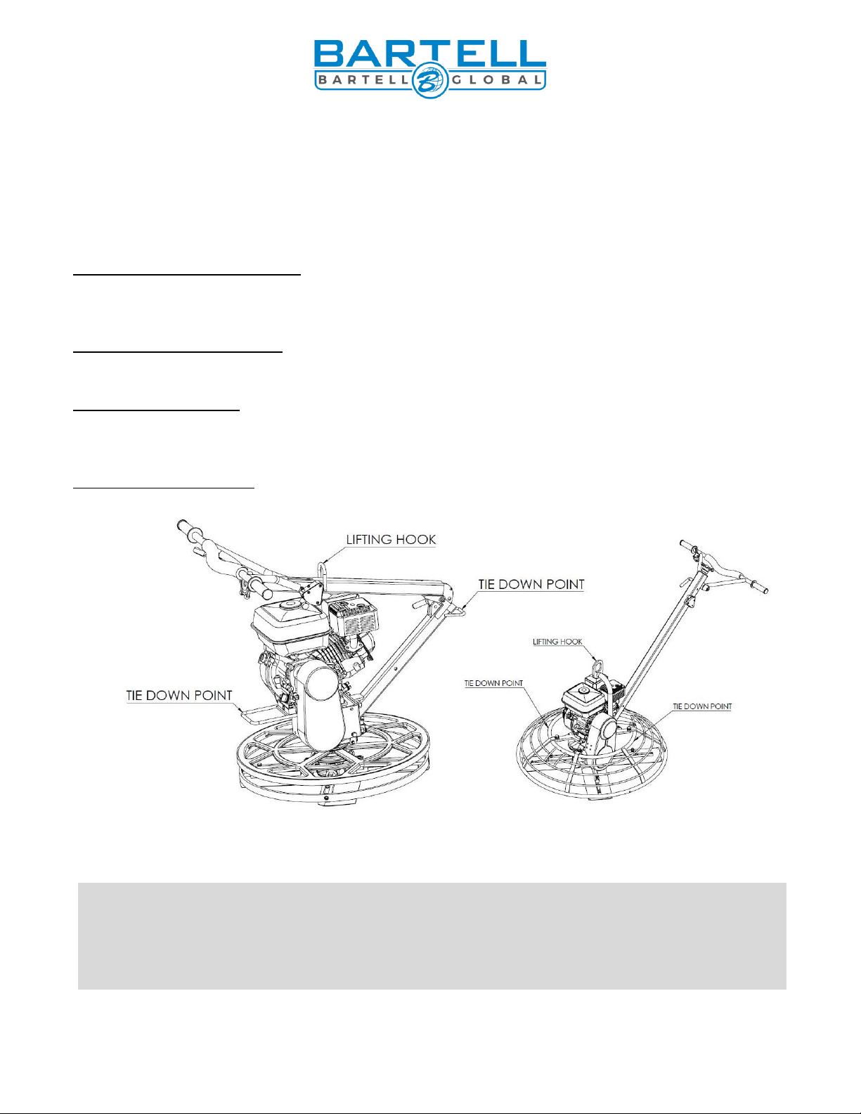
When lifting from above via a crane, forklift, etc. always use the hoist hook. The hoist hook is an
optional feature that can be mounted to the engine or a feature built in to the folding handles.
Recommended Tie Down Points
Edger Trowel w/folding handle –Always make sure handle is folded and lock pin is installed
while transporting. The front carry handle and the rear carry handle can be used as tie down
points.
Edger Trowel w/rigid handle –The front carry handle and base of the handle can be used as tie
down points. Wrap the tie down strap around the base of the handle for best results.
B436 w/folding handle –Always make sure handle is folded and lock pin is installed while
transporting. The top ring of the guard ring and the rear carry handle can be used as tie down
points.
B436/446 w/rigid handle –Use the top ring of the guard ring as a tie down point. Use 2-4 tie
downs space evenly apart for best results
EDGER TROWEL CAUTION: Never lift the trowel by the rotating ring; use the hoist
hook or handle provided on the trowel.
ALL TROWEL CAUTION: Remove the float disc when lifting machine more than
100cm (40”). The floating disc is loosely secure, so it may fall off.
Trowel recommended tie down locations and over head lifting points
This manual suits for next models
6
Table of contents
Other Bartell Global Trowel manuals


Popular Trowel manuals by other brands

Norton
Norton MTA 36 Operating instructions and spare parts list

Beton Trowel
Beton Trowel BT120H270 instruction manual

MULTIQUIP
MULTIQUIP Whiteman STXD6i Operation manual

MULTIQUIP
MULTIQUIP hhn34tvdtcsl4 Operation manual

Isoplam
Isoplam L030001 User manual and spare parts list

Flextool
Flextool PORTATROWEL FPT30 operating instructions


