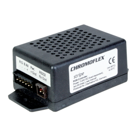
Barthelme CHROMOFLEX PRO KNX User manual

GEBRAUCHS-
ANWEISUNG
FÜR
CHROMOFLEX PRO
KNX „V2“ UND „V3“
BITTE AUFMERKSAM LESEN UND
AUFBEWAHREN!
Art.-Nr. 66000374 - 4-Kanal
1. EINFÜHRUNG
Der CHROMOFLEX Pro KNX ist entwickelt
worden, um spannungsgesteuerte LEDs
auf bis zu 4-Ausgangs-Kanälen über ei-
nen KNX-Bus zu steuern. Die Anzahl der
verwendeten Ausgangskanäle, Art Dimm-
kurve sowie viele weitere Einstellungen
können über die ETS-Software eingestellt
werden (siehe Kapitel 7.1).
2. BESTIMMUNGSGEMÄSSE
VERWENDUNG
Das Steuergerät ist für trockene Innenräu-
me konzipiert! Sollten sich dafür geeignete
LEDs im Außen- oder Feuchtbereich befin-
den, ist für ausreichenden Schutz (IP67) zu
sorgen.
Das Steuergerät darf nur mit einer an die
LEDs angepassten Stromversorgung be-
trieben werden. Andere Verbraucher als
LEDs (insbesondere induktive Verbraucher,
wie etwa Motoren, Trafos oder Drosseln)
können das Gerät zerstören.
Sollten diese zuvor genannten Punkte nicht
eingehalten werden, kann es zum Kurz-
schluss oder elektrischen Schlag kommen.
Der CHROMOFLEX Pro KNX wurde nach
den Richtlinien der „KNX Association“ ent-
wickelt. KNX (zuvor EIB) ist eine standardi-
sierte digitale Kommunikationsschnittstel-
le im Bereich der Gebäudeautomation.
WARNUNG 1:
LEDs können eine sehr hohe Lichtintensität
entwickeln, selbst im gedimmten Zustand!
Speziell in Verbindung mit Optiken können
selbst schwache LEDs sehr gefährlich wer-
den. Der direkte Blick in LEDs kann irrepa-
rable Schäden an der Netzhaut des Auges
hervorrufen. Verwenden Sie Diusoren zur
Lichtstreuung.
WARNUNG 2:
Bitte beachten Sie, dass LED-Licht seine
Intensität sehr schnell wechseln kann.
Schnell wechselnde Lichteekte können
die Wahrnehmung beeinflussen, Beschwer-
den hervorrufen, oder Anfälle bei Personen
mit Neigung zu Epilepsie auslösen.
3. TECHNISCHE DATEN
Betriebsspannung:
10V bis 48V DC
Schutzklasse:
III
Ausgangsstrom:
max. 2,2A / Kanal
Maße (L|B|H):
180|52|22 mm
Eigen-Stromverbrauch (ohne LED):
ca. 5 - 20mA
Umgebungstemperatur:
0°C - max. +50°C
(Betrieb nur in trockenen Innenräumen
mit ausreichender Luftzirkulation zur Wär-
meabfuhr, nicht betauend)
Schutzart:
IP 20
Hersteller: Josef Barthelme GmbH & Co. KG
4. SICHERHEITSHINWEISE
Das Gerät erzeugt bei Betrieb Wärme.
Auf ausreichende Luftzirkulation muss
geachtet werden. Das Gerät darf sich im
Regelbetrieb bei max. Last nicht mehr
als auf 80°C erwärmen.
Es ist unbedingt auf die richtige Polung
der Anschlüsse zu achten. Das Modul
verfügt intern über einen Verpolungs-
schutz, trotzdem kann Verpolen (auch
kurzzeitig) das Gerät zerstören.
Beim nicht bestimmungsgemäßem Be-
trieb, Verpolen, bei Umbau des Gerätes,
bei Sach- oder Personenschäden, die
durch unsachgemäße Handhabung oder
Nichtbeachten der Sicherheitshinweise
verursacht werden, übernimmt Barthel-
me keinerlei Haftung und der Garantie-
anspruch erlischt vollständig.
Sofern sich die LEDs im Feuchtbereich
(z.B. Schwimmbäder, Sauna,...) befinden,
ist besonders auf die geltenden Vor-
schriften
bezüglich der Stromversorgung
zu achten.
Die Installation des Produktes darf nur
durch eine qualifizierte Fachkraft erfolgen,
die mit den geltenden Vorschriften (z.B. DIN,
VDE, EN) vertraut ist.
Dieses Produkt ist kein Spielzeug und ge-
hört nicht in Kinderhände. Auch LEDs kön-
nen sehr heiß werden! Es ist in jedem Fall
ratsam, die vorgegebene Maximaltempera-
tur der Leuchtmittel nicht zu überschreiten,
da sich dies nachhaltig auf Lebensdauer
und Lichtintensität der LEDs auswirken
kann.
5. MONTAGE
Der elektrische Anschluss darf nur durch
eine Elektrofachkraft durchgeführt wer-
den, die mit den geltenden Richtlinien
vertraut ist!
Vorsicht: Schalten Sie die Stromversor-
gung bzw. die Anschlussleitung span-
nungsfrei, bevor Sie jegliche Arbeiten
vornehmen!
MONTAGEORT
Achten Sie darauf, dass das Produkt auf
einen stabilen, ebenen, kippfesten Unter-
grund montiert wird. Das Gerät erzeugt
beim Betrieb Wärme. Auf ausreichende
Luftzirkulation muss geachtet werden.
ABB.: 1
Abmessungen/Montagelöcher
2252
152,60
180

6. ANSCHLUSS
Bitte beachten Sie, dass die LEDs unbe-
dingt im stromlosen Zustand des Dimmers
angeschlossen werden müssen.
HINWEISE ZUR WAHL DES NETZTEILES:
Wichtig: Das Netzteil muss über entspre-
chende Puls-Belastbarkeit verfügen. Un-
stabilisierte oder zu schwache Netzteile
können Flackern bei Farbübergängen
hervorrufen.
Wichtig: Die Spannungsversorgung muss
auf die verwendeten LEDs abgestimmt
sein! Eine ungeeignete Spannungsver-
sorgung kann zu Funktionsstörungen,
unerwünschtem Flackern, Zerstörung der
LEDs, Zerstörung der Elektronik, oder im
schlimmsten Fall zu Überhitzung führen.
Wir raten dringend von der Verwendung
unstabilisierter Billig-Netzteile ab! Auch
Spezielle „LED“-Netzteile sind meist un-
geeignet, da diese bereits Steueuerungs-
Elektronik für Konstant Strom enthalten
können, welche nachgeschaltete Steuer-
geräte (wie etwa der CHROMOFLEX Pro)
nicht vertragen!
Wir empfehlen in jedem Fall Spannungs-
versorgungen in Schaltnetzteil-Techno-
logie! Geeignete Netzteile sind bei uns
erhältlich.
Ein Netzteil kann natürlich auch mehrere
Module gleichzeitig speisen. In diesem Fall
ist auf ausreichende Leistung des Netz-
teils zu achten. Zur Verdrahtung können
Leitungen mit einem Querschnitt von ma-
ximal 2,5 mm² verwendet werden.
Die Module sollten mit mindestens 10 Volt
versorgt werden, die maximal zulässige
Spannung beim CHROMOFLEX Pro KNX CV
beträgt 48 Volt
ABB.: 2
230V AC
10V bis 48 V DC
KNX
BUS
ANMERKUNGEN/ERGÄNZUNGEN
Bei den Ausgangskanälen bitte
• Verpolung vermeiden
• auf korrekte Spannung achten
• sicherstellen, dass die Leistung je Aus-
gangskanal nicht überschritten wird
• keinesfalls stromgesteuerte LEDs (CC)
anschließen.
Hinweis zu unseren LED-Streifen:
Von uns gelieferte LED-Streifen sind üb-
licherweise auf Rollen mit maximal ca. 6
Metern Länge, der Stromverbrauch ist
etwa 1 Ampere bei 24 Volt pro Farbe. Beim
Modell „CHROMOFLEX Pro KNX CV“ be-
trägt der max. Strom beim 4 Kanal System
2,2 Ampere pro Kanal (Abb. 3). Bei Verwen-
dung nur eines Kanals (Abb. 4) können 8,8
Ampere genutzt werden. Hierbei ist unbe-
dingt darauf zu achten, dass alle Ausgänge
miteinander gebrückt werden!
Bei der Verwendung von „1 Channel Tun-
able White“ werden die Kanäle 1 und 2 für
eine Farbtemperatur gebündelt, sowie die
Kanäle 3 und 4 für die zweite Farbtempe-
ratur.
6.1 CHROMOFLEX PRO KNX CV
„CV“ steht für „Constant Voltage“, also
Konstantspannung. Dieses Modell ver-
fügt über keine Strombegrenzung. Es
gibt die Versorgungsspannung direkt an
die LED-Streifen weiter. Wenn also der
LED-Streifen 12 Volt benötigt, muss dies
auch die Spannung des vorgeschalteten
Netzteils sein.
Hinweis:
In der Praxis sind LED-Streifen mit 12 Volt,
24 Volt und 48V üblich. LED-Streifen kön-
nen teilweise, je nach Länge, sehr hohe
Ströme benötigen.
ABB.: 3
ABB.: 4
W/A
B
G
R
4
3
2
1
CH Imax. 4x2,2A
ta:0-50°C
tc:80^C
10..48VDC PWR
IN
COM
max. 32A
W/A
B
G
R
4
3
2
1
CH Imax. 4x2,2A
ta:0-50°C
tc:80^C
10..48VDC PWR
IN
COM
max. 32A
7. BETRIEB
Betreiben Sie das Produkt nur, wenn es
einwandfrei funktioniert. Im Fehlerfall
schalten Sie das Produkt sofort aus und
betreiben es erst wieder nach Überprü-
fung durch eine Elektrofachkraft. Dies ist
der Fall, wenn:
• sichtbare Beschädigungen auftreten
• das Produkt nicht einwandfrei arbeitet
• es qualmt, raucht, oder bei hörbaren
Knistergeräuschen
• eine Überhitzung zu erkennen ist
Reparaturen des Produktes oder Arbeiten
an netzspannungsführenden Teilen dürfen
nur Fachkräfte des Elektrohandwerks vor-
nehmen.
WARNUNG: Hier besteht sonst Lebensge-
fahr durch elektrischen Schlag!
So vermeiden Sie Störungen und Brand-
gefahren:
•
Decken Sie das Produkt nicht ab. Beein-
trächtigen Sie nicht die Luftzirkulation.
•
Hängen und befestigen Sie nichts an dem
Produkt, insbesondere keine Dekoration.
Lassen Sie Kinder nicht unbeaufsich-
tigt mit elektrischen Produkten spielen!
Kinder können Gefahren im Umgang mit
elektrischer Energie nicht immer richtig
einschätzen.

7.1 ERST-INBETRIEBNAHME
Schließen Sie die CHROMOFLEX Pro KNX
Geräte gemäß Ihrer gewünschten An-
wendung an. Stellen Sie sicher, dass ent-
sprechende LED Streifen und das richtige
Netzteil an den CHROMOFLEX Pro KNX CV
angeschlossen sind.
Zur Programmierung wird die aktuelle
ETS Software benötigt. Die für die ETS
benötigten Dateien können von unserer
Internetseite „www.barthelme.de“ be-
zogen werden.
Zusätzlich finden Sie auf unserer In-
ternetseite eine deutsche Erläuterung
aller Parameter und Kommunikations-
Objekte.
8. LIEFERUMFANG UND ZUBEHÖR
Jedes CHROMOFLEX Pro KNX Modul wird
mit dieser Anleitung geliefert. Sie ist
Bestandteil des Lieferumfangs für das
Gerät und muss dem Endverbraucher
ausgehändigt werden.
WICHTIG:
Sämtliche CHROMOFLEX Anleitungen sind
im Internet unter www.barthelme.de
herunterladbar.
Bitte informieren Sie sich vor Verwen-
dung über Aktualisierungen!
KONTAKT
Josef Barthelme GmbH & Co. KG
Oedenberger Str. 149
90491 Nürnberg | Germany
T: +49 911 42 476 0
www.barthelme.de
TECHNISCHE ÄNDERUNGEN
VORBEHALTEN.
STAND 02|2016
NOTIZEN

INSTRUCTION
MANUAL
FOR
CHROMOFLEX PRO
KNX „V2“ AND „V3“
PLEASE READ THIS MANUAL CAREFULLY
AND KEEP IT IN A SAVE PLACE!
Item-No. 66000374 - 4-Channel
2. USAGE
The modules were designed for indoor use
in dry places. The LEDs might also be used
in wet environments or outdoors, if suited
for that purpose. For outdoor use, be sure
to use the right protection methods (IP67).
The modules must be operated with a pow-
er supply that is matched to the used LEDs!
Non-LED loads (especially inductive loads
like motors, transformers, coils, etc.) might
damage or destroy the module.
If any of the before mentioned points is
not observed short circuit or electric shock
might occur.
The CHROMOFLEX Pro KNX was developed
according to KNX Guidelines. KNX is a stan-
dardized digital communications interface
in the field of building automation.
1. INTRODUCTION
The CHROMOFLEX Pro KNX has been de-
veloped to control voltage controlled LEDs
for up to 4 output channels via KNX. The
number of output channels, the type of dim-
ming curve and many other settings can be
easily set using ETS-software.
WARNING 1:
LED light may have very high intensi-
ty even when dimmed. Particularly in
connection with optics also weak LEDs
may be very dangerous. Staring into
LEDs may cause irreparable damage to
the eye‘s retina. Use diusers to spread
the intensity!
WARNING 2:
Please be aware that LED light may cau-
se side eects. This light changes intensi-
ty very fast! Changing light may aect the
perception and is also known to trigger
epileptic seizures in persons who are
photosensitive.
If the LEDs are provided in wet areas (e.g.
swimming pools, sauna, ...) pay particular
attention to the rules regarding the power
supply.
The installation of the product must be
performed by a qualified electrician who
is familiar with the applicable regula-
tions (e.g. DIN, VDE, EN).
This product is not a toy, keep away from
children! LEDs can get quite hot. We
strongly recommend ensuring maximum
operating temperature is not exceeded,
because this might reduce the expected
life time of the LEDs significantly.
4. SAFETY INSTRUCTIONS
The modules might produce some heat.
Care must be taken to provide unrestric-
ted air ventilation. The device should not
be warmer than 80°C in standard opera-
tion at max. load.
The unit is equipped with a limited pro-
tection against reverse polarity. Connec-
ting the power in reverse polarity can
destroy the module, even if connected for
a short time only.
Barthelme assumes no liability for per-
sonal or property injury if the device is
not used as directed, if the polarity is re-
versed or the safety instructions are not
observed. In these cases any warranty
claims are void.
3. TECHNICAL DATA VERSION CV
(EXCERPT)
Operating voltage: 10V to 48V DC
Protection class: III
Output current 4 channels:
max. 2.2A / channel
Dimensions (L|W|H): 180|52|22 mm
Current consumption of one unit
(without LED): about 5 - 20mA
Ambient temperature: 0°C - max. +50°C
(in dry conditions only with sucient
air circulation for heat dissipation, non-
condensing)
IP Protection: IP20
Manufacturer:
Josef Barthelme GmbH & Co. KG
5. INSTALLATION
The electrical connection must only be
carried out by a qualified electrician who
is familiar with the applicable regulations!
Caution: Turn o the power supply or the
connection lead before doing any works
ASSEMBLY SITE
Make sure that the unit is mounted on a
stable, plain, non-tilting base. In operation
the unit might produce heat. Care must
be taken to provide unrestricted air ven-
tilation.
FIG.: 1
Dimensions/Mounting holes
2252
152,60
180

FIG.: 2
230V AC
10V to 48 V DC
KNX
BUS
unsuitable as they may already contain
control electronics for constant current,
which may not be compatible with control
devices as the CHROMOFLEX Pro .
We always recommend switching power
supplies in power supply technology! Sui-
table power supplies are available from us.
One power supply can be used for several
units in parallel, if the maximum output
power of the supply is observed. For wi-
ring cables with a cross section of max.
2.5mm² can be used.
The modules should be provided with
min. 10 Volts; the maximum voltage of the
CHROMOFLEX Pro KNX is 48 Volts.
6. CONNECTION
Please note that the LEDs have to be
connected in a de-energised state of the
dimmer!
NOTES ON THE SELECTION OF THE POW-
ER SUPPLY:
Important: The power supply must have
appropriate pulse load. Unstabilized or too
weak power supplies may lead to unwan-
ted flickering eects in the color changes.
Important: The module must be operated
with a power supply, that is suitable for the
used LEDs! Improper power supplies may
lead to malfunctions, unwanted flickering
eects, destruction of LEDs, destruction of
electronics or in worst case to overheating.
We strongly recommend using high-qua-
lity (stabilized) switching power supplies!
We strongly advise against the use of
unstabilized cheap power supplies! Also
special „LED“ power supplies are usually
NOTES / ADDITIONS
At the output channels please
• avoid reverse polarity
• note correct voltage
• ensure that the power per output channel
is not exceeded
• never connect current-controlled LEDs
(CC)
Note:
We deliver flexible stripes on reels in
length of max. 6 metres, with a power
consumption of about 1 Amperes at 24
Volts per color. The „CHROMOFLEX Pro
KNX CV“ 4-channel version is able to con-
trol up to 2.2 amperes per channel (Fig. 3).
It is possible to use 1-channel with 8.8 am-
peres, but it is very important to bridge all
channel outputs (Fig. 4).
For the use of „Channel 1 Tunable Whi-
te“ the channels 1 and 2 are bundled to-
gether for a color temperature, as well as
the channels 3 and 4 for the second color
temperature.
6.1 CHROMOFLEX PRO KNX CV
„CV“ is an abbreviation for constant voltage.
This model does not have any internal
current regulator. Supply voltage is pas-
sed through and the voltage of the power
supply must match the voltage of the LED
stripe. So if the LED strip requires 12 volts,
this must also be the output voltage of the
power supply.
Note:
LED stripes of 12 Volts, 24 Volts and 48
Volts are oered on the market. Depending
on the cable length the used LEDs might
need very high currents.
FIG.: 3
FIG.: 4
W/A
B
G
R
4
3
2
1
CH Imax. 4x2,2A
ta:0-50°C
tc:80^C
10..48VDC PWR
IN
COM
max. 32A
W/A
B
G
R
4
3
2
1
CH Imax. 4x2,2A
ta:0-50°C
tc:80^C
10..48VDC PWR
IN
COM
max. 32A
How to avoid malfunctions or fire risk:
• Do not aect air circulation by covering
the unit.
• Do not attach anything to the unit e.g. de-
coration items etc.
Do not let your children play unattended
with electrical equipment. Children cannot
always perceive possible dangers correctly.
7. OPERATION
Please operate this unit only, when it
is working properly. In case of an error,
switch o the unit immediately. Do not
operate the unit, until the unit was verified
electronically by a qualified electrician.
A case of error is:
• visible signs of damage on the unit
• the unit is not working properly
• fume rising or crackling sounds from the
unit
• visible signs of overheating
Maintenance and service which require
access to live components inside the unit
must be carried out by an authorized elec-
trician.
WARNING: Danger of life! Risk of electric
shock!

NOTES
CONTACT
Josef Barthelme GmbH & Co. KG
Oedenberger Str. 149
90491 Nuremberg | Germany
T: +49 911 42 476 0
www.barthelme.de
SUBJECT TO TECHNICAL
CHANGES.
VERSION 02|2016
8. CONTENTS AND ACCESSORIES
Connect LEDs and power supply as shown
in fig. 2 and 3. Make sure that LED-stripes
and correct power supply are connected
to CHROMOFLEX Pro KNX CV.
IMPORTANT NOTE:
For programming you need the newest
version of ETS software. Needed files for
the ETS software can be found at our web-
page www.barthelme.de.
Additionally you can find the explanation of
all parameters and group objects on this
webpage.
7.1 START-UP
Connect LEDs and power supply as per
your application. Make sure that LED-stri-
pes and correct power supply are connec-
ted to CHROMOFLEX Pro KNX CV.
For programming you need the newest
version of ETS software. Needed files for
the ETS software can be found at our web-
page www.barthelme.de.
Additionally you can find the explanation
of all parameters and group objects on
this webpage.
Table of contents
Languages:
Other Barthelme Remote Control manuals
