Bartington SCU1 User manual

Operation Manual for
SCU1 Signal Conditioning Unit

BARTINGTON INSTRUMENTS
Page 2 of 19 OM2441/1
Table of Contents
1. About this Manual 4
1.1. Symbols Glossary 4
2. Safe Use 4
3. Compatible Magnetometers 5
4. Introduction to the SCU1 5
4.1. Summary 5
4.2. Functional Description 5
4.2.1. Power 5
4.2.2. Signal Conditioning 5
5. SCU1 Inputs, Outputs and Controls 7
5.1. Back Panel Connections and Controls 7
5.2. Front Panel Displays and Controls 8
6. Installing the SCU1 10
6.1. Location of the Equipment 10
6.1.1. Environmental Precautions 10
6.1.2. Mounting 10
6.1.3. Orientation 10
6.1.4. Temperature 10
6.1.5. Proximity to Other Equipment 10
6.2. Connecting the Equipment 11
6.3. Initial Settings 11
6.3.1. Magnetometer Supply Voltage 11
6.3.2. Magnetometer Output Type Selection 11
7. Using the SCU1 12
7.1. Output Scaling 12
7.1.1. Converting Output Voltage to Magnetic Units 12

BARTINGTON INSTRUMENTS
Page 3 of 19 OM2441/1
7.2. Over-range Condition 12
7.3. Switching ON and OFF 13
7.4. Using the SCU1 Controls 13
7.4.1. Offset Controls 13
7.4.2. Gain Controls 13
7.4.3. Low Pass Filter (LPF) 14
7.4.4. High Pass Filter (HPF) 14
7.5. Using the SCU1 Outputs and Displays 15
7.5.1. Unconditioned and Conditioned Outputs 15
7.5.2. Display Panel Meters 15
8. Troubleshooting 16
9. Care and Maintenance 17
9.1. Fuses 17
9.2. Calibration 17
9.3. Cleaning 17
10. End of Life Disposal 18
Notes 18

BARTINGTON INSTRUMENTS
Page 4 of 19 OM2441/1
1. About this Manual
This manual provides the information necessary to help customers operate the SCU1 Signal
Conditioning Unit from Bartington Instruments. It should be read in conjunction with product
brochure DS2519, which can be found on the SCU1 product page on the Bartington Instruments
website at: www.bartington.com.
1.1. Symbols Glossary
The following symbols used within this manual call your attention to specific types of
information:
WARNING: Indicates a situation in which serious bodily injury or death could result if the
warning is ignored.
Caution: Indicates a situation in which bodily injury or damage to your instrument, or both,
could result if the caution is ignored.
Identifies items that must be disposed of safely to prevent unnecessary damage to the
environment.
Note: Provides useful supporting information on how to make better use of your purchase.
2. Safe Use
WARNING: These products are not qualified for use in explosive atmospheres or life
support systems. Consult Bartington Instruments for advice.
WARNING: The SCU1 is powered by mains electricity. The unit MUST be earthed. The
centre pin of the IEC inlet on the rear panel is internally connected to all the metal panels
of the unit. Use the 3-core connecting cable supplied with the unit to ensure the unit is
correctly earthed. Use of an alternative cable may render the unit unsafe.
WARNING: The IEC mains inlet socket must be fitted with two fuses of the type specified in
the product brochure.
WARNING: This unit is not sealed against the ingress of water and must only be operated
under dry conditions.

BARTINGTON INSTRUMENTS
Page 5 of 19 OM2441/1
3. Compatible Magnetometers
The SCU1 is designed to be compatible with the sensors shown on the Product Compatibility
page of the Bartington Instruments website at: www.bartington.com/product-compatibility.html.
Caution: Use of incompatible sensors may cause damage to the SCU1 and/or the sensor.
4. Introduction to the SCU1
4.1. Summary
The SCU1 Signal Conditioning Unit combines the functions of a power supply unit, an
analogue signal conditioner and a display unit for use with compatible Bartington Instruments
magnetometers.
The unit connects to a single three-axis magnetometer and enables the user to monitor the X, Y
and Z magnetic field components via the following outputs:
• unconditioned analogue outputs (signals), direct from the magnetometer
• conditioned analogue signals (the magnetometer signals modified by the SCU1 analogue
conditioning)
• digital display meters.
The SCU1 is suitable for use in many situations including:
• where analogue signals from the magnetometer require adjustment to match the input
requirements of control electronics or of an analogue to digital (A-to-D) converter system
• as a three-axis magnetic field meter, giving a digital display of the X, Y and Z values from
the magnetometer
• where both a digital display and analogue voltage signals are required.
4.2. Functional Description
4.2.1. Power
The SCU1 includes an integral power supply for the attached magnetometer.
4.2.2. Signal Conditioning
The SCU1 applies three stages of analogue processing, converting the unconditioned
magnetometer outputs into the conditioned outputs.

BARTINGTON INSTRUMENTS
Page 6 of 19 OM2441/1
1. Filtering: Signals can be filtered (using low and high pass filters) to remove unwanted
frequencies.
2. Offset: In the second stage, a DC offset voltage can be added to or subtracted from the
magnetometer output signal, producing a DC adjusted output.
3. Gain: Finally, the DC adjusted output signal can be amplified by a variable gain stage, to
produce the conditioned output signal.
Offset and gain are controlled independently for the X, Y and Z channels, but the filter settings
are common to all three.
The conditioned output signals and the original magnetometer (unconditioned) output signals
are available as analogue voltages from the SCU1. In addition, the DC components of each
conditioned signal are displayed digitally on display meters.

BARTINGTON INSTRUMENTS
Page 7 of 19 OM2441/1
5. SCU1 Inputs, Outputs and Controls
5.1. Back Panel Connections and Controls
Figure 1. Back panel connections and controls.
Key to Figure 1
1. Unconditioned Outputs. These three BNC connectors provide buffered versions of the X,
Y and Z output signals from the magnetometer. Signals are only valid when the SCU1 is
switched ON. They are not affected by any of the other SCU1 controls.
2. Magnetometer Socket. This multi-pin socket is for the connection of the magnetometer
cable.
3. Magnetometer Output Type Selector Switch. The SCU1 can be used with magnetometers
that have unbalanced (single-ended) outputs or balanced (differential) output signals. This
switch sets the SCU1 to operate in unbalanced or balanced mode.
Caution: This switch must be set to match your magnetometer output type (see
Magnetometer Output Type Selection).
4. IEC Mains Socket (Electrical Supply Input). The unit requires an AC mains supply as
specified in the product brochure via this IEC inlet socket.
WARNING: The socket includes a removable fuse carrier. The correct fuse types must be
fitted. Refer to the product brochure for fuse details.
5. ON/OFF Switch. The IEC inlet socket includes this ON(1)/OFF(0) switch, to control power to
the unit.
1 2 3 4
5
6
BARTINGTON INSTRUMENTS
Page 8 of 19 OM2441/1
6. Conditioned Outputs. These three BNC connectors carry the conditioned analogue output
voltages. The conditioned outputs are the magnetometer X, Y and Z signals after they have
been modified by the filter, gain and offset controls.
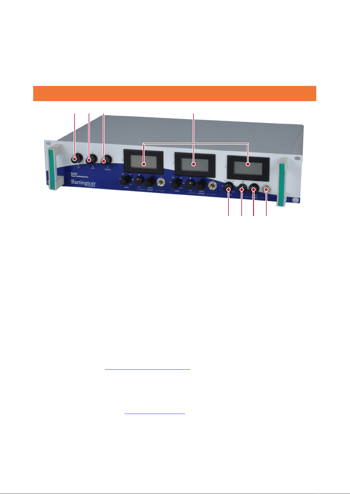
5.2. Front Panel Displays and Controls
Figure 2. Front panel displays and controls.
Key to Figure 2
7. Low Pass Filter (LPF) Control. The SCU1 applies low pass filtering to the magnetometer
output signals. This control sets the -3dB point frequency for the LPF.
Note: The LPF cannot be completely disabled.
8. High Pass Filter (HPF) Control. The SCU1 can apply high pass filtering to the magnetometer
output signals. This control sets the -3dB point frequency for the HPF.
9. Magnetometer Supply Voltage Control. This control sets the voltage that the SCU1 supplies
to the magnetometer connector power pins. This enables the user to vary the voltage
to compensate for cable voltage loss, ensuring the required voltage is present at the
magnetometer. See Magnetometer Supply Voltage for guidance on matching voltage to cable
length.
10. Display Panel Meters. The conditioned output voltages for the three channels are displayed
numerically on these 3½ digit meters. The meters display in volts and should only be used for
low frequency signals. See Display Panel Meters for full details on how to use the meters.
7 8 9 10
11121314

BARTINGTON INSTRUMENTS
Page 9 of 19 OM2441/1
11. Offset Switches (one for each channel). These 3-position switches control the polarity of the
offset DC voltages applied to the magnetometer output signals (see Table 1 below). There is
an individual switch for each of the X, Y and Z channels.
Switch Position Polarity Function
Centre OFF No offset
Up + Offset voltage is added
Down - Offset voltage is subtracted
Table 1. Oset switch functions.
12. Offset Coarse Controls (one for each channel).
13. Offset Fine Controls (one for each channel). These rotary controls set the offset DC voltages
applied to each of the X, Y and Z channels. For guidance on use of the offset controls see
Offset Controls.
14. Gain Controls (one for each channel). These controls set the gain (amplification) that is
applied to each of the X, Y and Z channels.
Note: The effect of the gain control is dependent on the offset voltage. See Gain Controls
for guidance on use of the gain and offset facilities.

BARTINGTON INSTRUMENTS
Page 10 of 19 OM2441/1
6. Installing the SCU1
6.1. Location of the Equipment
6.1.1. Environmental Precautions
WARNING: This equipment is powered by mains electricity. It should not be used in wet or
damp locations, where water may enter the unit and create a safety hazard.
Refer to the product brochure for maximum environmental ratings for the SCU1.
Caution: Exceeding the maximum environmental ratings may cause irreparable damage to
the equipment.
6.1.2. Mounting
The SCU1 can be used:
• free-standing, on a bench-top, or
• mounted in a 19” rack, using the integral side brackets.
6.1.3. Orientation
The SCU1 can be orientated horizontally or vertically.
6.1.4. Temperature
To minimise temperature induced drift effects, position the SCU1:
• in a constant ambient temperature
• out of direct sunlight.
6.1.5. Proximity to Other Equipment
The SCU1 contains no high frequency electronics likely to cause emissions which could cause
interference with other equipment. The unit is unlikely to be affected by interference from other
equipment in the normal operating environment.
Note: The sensors used with this unit, being designed to measure magnetic fields, are
susceptible to electromagnetic interference. Avoid operation close to high frequency
sources of radiation. Interference is indicated by instability in the reading when the sensor
is maintained in a fixed position.

BARTINGTON INSTRUMENTS
Page 11 of 19 OM2441/1
6.2. Connecting the Equipment
Connect the equipment using the following sequence:
1. Connect the magnetometer to the SCU1 magnetometer socket. Ensure the connector pins
are correctly aligned with those in the socket. The locking ring should be hand-tightened
only.
2. If your system will use the SCU1 analogue outputs, connect the conditioned and/or
unconditioned BNC outputs to your external equipment, as required.
3. Ensure the IEC socket mains switch (Figure 1, item 5) is OFF (position 0). Connect your
mains supply cable to the IEC socket. The unit will operate with a mains supply in the range
specified in the product brochure. Range selection is automatic within the unit.
6.3. Initial Settings
6.3.1. Magnetometer Supply Voltage
Before switching the equipment ON, set the appropriate voltage for your magnetometer, using
the front panel control (Figure 2, item 9).
For all Mag648 and Mag-03RC magnetometers, use the 12V setting.
For Mag-03MC, MS and IE magnetometers, the voltage setting should be used to compensate for
any voltage loss in the magnetometer cable. Refer to individual sensor brochures to select the
correct setting for your cable length (see the Mag-03 product brochure DS0013, available from
the Bartington Instruments website, for recommended cable types).
6.3.2. Magnetometer Output Type Selection
Before switching on the equipment, set the magnetometer output type selector switch (Figure
1, item 3) to the correct position for your magnetometer: see Table 2. See individual sensor data
sheets for those not mentioned in this table.
Magnetometer Output Type
Mag-03MS Unbalanced
Mag-03MC Unbalanced
Mag-03IE Unbalanced
Mag-03RC Balanced
Mag648 Balanced

BARTINGTON INSTRUMENTS
Page 12 of 19 OM2441/1
Table 2. Magnetometer output types.
7. Using the SCU1
7.1. Output Scaling
7.1.1. Converting Output Voltage to Magnetic Units
The conditioned output voltage at the output connectors is displayed on the panel meters
and can be converted into magnetic field strength units (e.g. Tesla). The conversion will
depend on the range of your magnetometer, analogue output voltage, and scale factor of your
magnetometer.
Scale factor = range / analogue output of magnetometer. For example:
• a magnetometer with a range of 250μT and an analogue output of ±10V has a scale factor of
25
• a magnetometer with a range of 60μT and an analogue output of ±3V has a scale factor of 20.
To convert voltage to field strength:
1. Divide the output voltage by the gain control setting, then
2. Multiply by the scale factor for your magnetometer.
For example, if the display for the X axis shows 6.5V when connected to a magnetometer with a
range of 250μT and an analogue output of ±10V, with SCU1 gain = 50, this indicates an X axis field
of:
(6.5/50) x (250/10) = 3.25µT
7.2. Over-range Condition
The SCU1 conditioned output and display meter readings are only accurate when in the range
-10V to +10V. Readings beyond -10 to +10V are considered over-range as they will not be to the
specification accuracy.
Note: Use the offset and gain controls, as described in Using the SCU1 Controls, to ensure
the conditioned outputs do not go over-range.

BARTINGTON INSTRUMENTS
Page 13 of 19 OM2441/1
7.3. Switching ON and OFF
Caution: Connect the magnetometer before switching on the SCU1, as connecting a live
cable to the magnetometer may cause damage. Similarly, switch off the SCU1 before
disconnecting the magnetometer.
Caution: The SCU1 should be switched on and off using the IEC socket switch (Figure 1,
item 4) (“0” = OFF, “1” = ON).
Note: For best results, after switching ON, leave the SCU1 for 10 minutes for the internal
temperature to stabilise, before performing any measurements.
7.4. Using the SCU1 Controls
7.4.1. Offset Controls
The offset controls apply a DC offset value to the magnetometer output voltage, to generate a DC
adjusted signal voltage. This resulting voltage will be amplified by the gain controls, to form the
final SCU1 conditioned output signal.
The offset voltage range limits are -10 to +10V.
The offset control includes a coarse adjust, to set an approximate level, and a fine adjust to
achieve the exact offset level desired. A polarity switch selects whether the offset is added to or
subtracted from the magnetometer output, or set to OFF (zero offset).
Offset is generally used where an AC magnetic field being investigated is superimposed on a
background static (DC) field. The DC signal can be eliminated from the SCU1 conditioned output
by applying offset. The conditioned output will then contain only the AC signal, which can be
investigated at high resolution by using gain (amplification).
Example: to remove the background DC field from the X channel:
1. Set the X channel gain to 1, and the HPF to DC.
2. Set the X channel offset polarity switch to the centre position (no offset).
3. If the X channel meter shows a + reading, set the offset polarity to -; if meter shows -, set
offset polarity to +.
4. Adjust the offset controls until the meter reading decreases to zero.
7.4.2. Gain Controls
The gain controls apply amplification to the DC adjusted signals from the offset stage, to
generate the SCU1 conditioned analogue outputs.

BARTINGTON INSTRUMENTS
Page 14 of 19 OM2441/1
Gain is a simple multiplication of the signal, so a gain of 300 will, for example, convert a
1mV signal into a 300mV signal at the output. Gain can be set to 1, 50, 100, 300, 500 or 1000,
independently for the three channels.
Note: Excessive gain will result in the SCU1 output becoming over-range. When applying
gain, start with gain = 1 and increment the control until you find the maximum setting that
does not cause the over-range condition.
Note: Both AC and DC components of the adjusted magnetometer signals are amplified by
the gain. If a signal contains a large DC component, gain may cause the output to go over-
range. To prevent this, the DC component can be removed using the offset controls.
In general, gain is used to improve measurement resolution of small signals, usually when
studying AC fields or very slow changes to a background DC field. In these situations, any DC
signal present would normally be removed by using offset. This allows the level of gain to be set
as high as possible, without the output becoming over-range.
7.4.3. Low Pass Filter (LPF)
The LPF attenuates high frequencies above the -3dB setting, reducing their amplitude in the
SCU1 conditioned outputs. The LPF is intended to be used for removal of unwanted frequencies
present in the magnetic field being measured.
The LPF -3dB frequencies settings are 1, 10, 100, 1000 and 10000Hz.
The LPF cannot be completed disabled. If LPF is not required, use the 10000Hz setting to ensure
the maximum signal bandwidth is available.
7.4.4. High Pass Filter (HPF)
The HPF implements AC coupling of the magnetometer input signals, attenuating low frequency
signals below the HPF -3dB setting. The HPF is intended for the removal of DC and very slowly
changing signals.
The HPF -3dB frequencies settings are 0.01Hz, 1Hz, and OFF.
Use OFF when HPF (AC coupling) is not required.

BARTINGTON INSTRUMENTS
Page 15 of 19 OM2441/1
Note: When using the 0.01Hz setting, allow sufficient time (up to 1 minute) for the filter to
settle. Momentary selection of the 1Hz setting will shorten the settling time.
Note: The offset control can be used at the same time as using high pass filtering, but it
is not normally required. It is recommended that the offset control be switched to the OFF
position when using the HPF.
7.5. Using the SCU1 Outputs and Displays
7.5.1. Unconditioned and Conditioned Outputs
The SCU1 analogue outputs should be used when both the AC and DC content of the signals need
to be measured (e.g. with an oscilloscope, meter or an A-to-D system) or when a voltage output
is required for connection, for example, to a feedback or control system.
Note: The unconditioned outputs should be used if access to the direct analogue output
signals from the magnetometer is required.
Note: The conditioned outputs should be used to access the magnetometer output signals
after the application of filtering, offset and gain by the SCU1.
Consult the product brochure for maximum load.
To convert the analogue voltage level into units of magnetic field at the magnetometer, refer to
Converting Output Voltage to Magnetic Units.
7.5.2. Display Panel Meters
The panel meters give a continuous digital display of the conditioned output voltage.

BARTINGTON INSTRUMENTS
Page 16 of 19 OM2441/1
The meter readings are in volts. To convert the analogue voltage level into units of magnetic field
at the magnetometer, refer to Converting Output Voltage to Magnetic Units.
Note: The meters are updated at 3 readings per second and hence will only indicate the DC
component (strictly, frequencies below 1Hz) present in the conditioned output voltage.
8. Troubleshooting
The SCU1 is unlikely to suffer any defects in normal use: no internal components are
serviceable. The most likely causes of failure, and their solutions, are detailed in the following
table.
In the event of any apparent malfunction beyond those described in the table below, please email
[email protected]om, or telephone the Bartington Instruments service team on +44 (0)1993
706565.
Fault Possible cause Solution
Panel meters are
off
Power fault Check SCU1 is connected to a mains supply.
Check the ON/OFF switch position.
Check the fuse in the IEC socket (see Fuses).
Conditioned
output shows an
unexpected DC
level, or is “stuck”
at a large + or -
value
High pass filter,
offset or gain
control settings
could be affecting
the signal
Ensure that the HPF is set to 0 (OFF).
Check that the relevant offset control is OFF.
If offset must be used, check the polarity is
correct.
Ensure the signal is not over-range due to
excessive gain.
Ensure you account for any gain applied in
your conversion of voltage to magnetic units.
AC signals are
distorted or clipped
Gain is too high Switch to a lower gain setting.
Magnetometer is
unusually hot
Power supply
voltage is too high
Lower the voltage supply to the
magnetometer.

BARTINGTON INSTRUMENTS
Page 17 of 19 OM2441/1
9. Care and Maintenance
The SCU1 requires no routine maintenance. The only user serviceable parts are the fuses in the
IEC mains inlet socket.
9.1. Fuses
To change a blown fuse, ensure the mains supply is disconnected, then extract the fuse block
from the IEC socket with a blunt tool (e.g. flat-bladed screwdriver). Extract and replace the blown
fuse. Replace the fuse block.
WARNING: Fuses fitted must be of the type specified in the product brochure.
9.2. Calibration
Return the SCU1 to Bartington Instruments for calibration at the recommended intervals. Refer
to the Calibration Certificate for further details.
9.3. Cleaning
WARNING: Disconnect the electrical supply before performing any cleaning operation.
Periodic cleaning is not normally required.
If the system becomes soiled and cleaning is necessary:
1. Use a damp cloth to clean the outer surfaces.
2. Use an air duster to blow debris from the connectors.
WARNING: Ensure water does not enter the system. The system must be completely dry
before the electrical supply is reconnected.
Caution: Never use chemicals, such as solvents, when cleaning the SCU1.
Caution: Take particular care when cleaning around electrical connections. Bent or
damaged pins may cause the magnetometer to malfunction.

BARTINGTON INSTRUMENTS
Page 18 of 19 OM2441/1
10. End of Life Disposal
This product (electrical and electronic equipment) should not be placed in municipal waste.
Check local regulations for disposal of electronic products.
Notes

OM2441/1
The copyright of this document is the property of Bartington Instruments Ltd.
Bartington® is a registered trade mark of Bartington Instruments Limited in the following countries:
United Kingdom, Australia, Brazil, Canada, China, European Union, India, Japan, Norway and the
United States of America.
Bartington Instruments Limited
5 Thorney Leys Business Park,
Witney, Oxford, OX28 4GE, England.
www.bartington.com
T: +44 (0)1993 706565
F: +44 (0)1993 774813
E: sales@bartington.com
Table of contents
Popular Test Equipment manuals by other brands


Wavecom
Wavecom TnP 3PLM 20A user manual

LeCroy
LeCroy 4300B Operator's manual

Atlas
Atlas BCX Series operating manual

Keithley
Keithley 213 Quick reference guide

Agilent Technologies
Agilent Technologies 11644A Series User's and service guide

Agilent Technologies
Agilent Technologies 8922 Supplementary User's Guide


