Basko Healthcare Swing Phase Lock 2 User manual
Gebruiksaanwijzing
Gebrauchsanleitung
Manual
Mode d’emploi
Swing Phase Lock 2
IQ88003 / Stand: 01/2018
Basko Healthcare
1505 HX Zaandam
Fax: +31 (0) 75 - 612 63 73
Internet: www.basko.com
Pieter Lieftinckweg 16
Tel.: +31 (0) 75 - 613 15 13
E-mail: verkoop@basko.com
BASKO HEALTHCARE
P. Lieftinckweg 16
NL 1505 HX Zaandam
Tel.: +31 75 613 15 13
Instructions
for use

This product is distributed in Sweden, Norway, Finland
and Denmark by
Camp Scandinavia AB
Karbingatan 38
SE-254 67 Helsingborg
Phone; +46 42 25 27 00
info@camp.se
www.camp.se

26
27
Swing Phase Lock 2Basko Healthcare
Basko Healthcare Swing Phase Lock 2
English
User directives................................................................ 29
Intended use / Indications ..................................................... 29
Indications ..............................................................29
Contraindications.........................................................30
Functional features / Other terms / Usages......................................29
Function ..................................................................... 30
Technical Features SPL 2 ...................................................30
Technical Features SPC .....................................................30
Technical Features Satellite .................................................30
Cleaning / disinfection Instructions............................................. 31
Maintenance Instructions...................................................... 31
Used Materials................................................................ 31
Constructional guidelines ..................................................... 31
Orthosis construction .......................................................31
Measuring ..............................................................31
Orthosis Construction .....................................................32
Joint Alignment ..........................................................32
Dynamic Initial Fitting ......................................................32
Function Check ..........................................................32
Adjusting locking and unlocking .............................................32
Satellite Control ..........................................................33
Shorten satellite cable .....................................................33
Checking all functions......................................................... 35
Package contents ............................................................. 35
Overview Parts ............................................................... 36
Parts SPL 2 Joint..........................................................36
Parts SPC Joint ...........................................................37
Parts Satellite............................................................38
Übersicht der Einzelteile
Satellit
Satellit - Einzelteile
Abb. Artikelnummer Einheit Artikelbezeichnung
AIQ141 1x SPL 2-Satellit (komplett)
BIQ141/01 1x Schraube für Serviceklappe (1 Stück)
CIQ141/02 1x Serviceklappe
DIQ141/03 1x Montageplatte
EIQ141/04 1x Schrauben für Montageplatte (2 Stück)
FIQ140/04 1x Kabelendstück
GIQ140/12 1x Maden-schraube für Kabelendstück
HIQ141/05 1x Kabel-Set (Teonkabel, Stahlkabel inkl. Endkugel)
IIQ140/06 1x Justierschraube
A
C
B
D
I
H
E
FG
ENG

28
29
Swing Phase Lock 2Basko Healthcare
Basko Healthcare Swing Phase Lock 2
User directives
Your doctor is the one whom prescribed the orthosis and stipulates the duration
of treatment. The daily use duration prescribed by the doctor must be observed
closely. The use of the orthosis is done under the supervision of the doctor.
The professional staff, which builds and adapts the articulation system into
the orthosis, is responsible for correct functioning of the Joints. In case of skin
problems, circulation problems, unusual pain or other complications, which to
your opinion are directly related to the product, please contact your doctor or
CO at once.
Intended use / Indications
Usage of the Swing Phase Lock 2 knee Joint system provides an optimum care for patients with Paresis/
Paralyses (e.g. Polio) and as a consequence contributes to a successful therapeutic treatment.Other
usage as prescribed above is not permitted.For a correct application the usage in combination with the
satellite in the orthosis is mandatory.The Joint system has been designed only as a non-weight bearing
Joint (KAFO/KO) and should not be used in any weight bearing orthoses.Non-observance of these
regulations excludes any liability claims.The Joint is available in two different version, for usage as a
monolateral Joint or as a bilateral Joint. When used in a monolateral construction, the maximum
patient weight cannot exceed more than 100 kg (220 lbs).
Indications
SPL 2 Orthotic Knee Joint bilateral and monolateral:
■Apoplexy (CVA) (ICD10: I64) ■Paralysis (ICD10: G83.9)
■Multiple sclerosis (ICD10: G35) ■Paresis (peripheral) (ICD10: G83.9)
■Myopathy (ICD10: G72.9) ■Poliomyelitis (ICD10: A80)
Contra Indications
SPL 2 Orthotic Knee Joint Bilateral SPL 2 Orthotic Knee Joint Monolateral
■Flexion Contracture > 10º (ICD10: M24.59) ■Patient weight > 100 kg
■Spasm ■Varus > 10° (ICD10: M21.10/Q74.9)
■Hip Contracture ■Valgus >10° (ICD10: M21.00/Q74.9)
■Weight bearing Orthosis ■Flexion Contracture > 5º
■Spasm
■Hip Contracture
■Weight bearing Orthosis
ENG

30
31
Swing Phase Lock 2Basko Healthcare
Basko Healthcare Swing Phase Lock 2
The 3 modes to manually control the SPL 2 Joint are:
1. Automatic locking
2. Permanent unlocking
3. Permanent locking
By deactivating the permanent unlocking mode the Satellite switches into the permanent locking
mode and needs to pushed into the Automatic function.
Cleaning / disinfection Instructions
The SPL 2 Joint may not be greased, oiled or in any other way lubricated.When cleaned, please use
Naphtha (no acetone, dilutions or turpentine, etc.) or some similar cleaning uids or compressed air.
Maintenance Instructions
Maintenance cycles depend strongly on the patients activity level.At a moderate activity level,
the Joints must be checked / serviced every 6 months.When doing this, attention must be paid to
wear and tear, Joint play and damages.If the Joint is no longer running freely, a thorough service is
recommended.
If the Joint has been, due to circumstances, extremely heavily loaded in a exed position e.g. with
stumbling, tripping or walking (falling) down the staircase, the Joint has to be inspected by the
Orthotist. In case the patient constantly walks with a slightly exed knee or regularly usage the safety
stops, adjustment of the extension position towards exion is absolutely necessary.
Used Materials
SPL 2 Joint: Housing: Stainless Steel; Function Unit: brass; Cover plates: ABS plastic
SPC Joint: Housing: Stainless Steel; Cover plates and Bumper Pin: ABS plastic
Satellite: Housing: ABS, POM plastic; Cable: Teon
Constructional guidelines
Orthosis construction
Measuring
Casting must be done with a fully, in neutral, extended leg.Stretching however should be possible
without to much effort to allow full extension (needed to unlock the Joint) once the Orthosis is worn.
When the Alignment Unit is used (Art. nr. IQ150) to construct the Orthosis, make sure the square with
the T-bar is placed horizontal in the Frontal Plane to keep the axis straight.Alignment should be based
on the plumb line to create a neutral baseline for the Function Unit.
Mode 1 Mode 2 Mode 3
Functional features / Other terms / Usages
This articulating system is meant to compensate weakened or Total Failure of the Knee Extension
function.
The SPL 2 Joint offers knee stability during stance and offers free movement of the knee during swing.
This feature is fully automatically activated with each step.It is prohibited to be used in water or
exposed to temperatures exceeding 50°C.
Important
The patient must be well informed concerning the functions and possibilities of the Knee Joint system.
Function
Technical Features SPL 2
The technique of the SPL 2 Joint (Swing Phase Lock) is based on a simple internal pendulum
mechanism, which locks and unlocks the knee depending on the angle of the Joint in the sagittal
plane.During gait, the device locks at the end of swing phase, just prior to heel strike, and unlocks the
knee at heel off in preparation for swing. The Joint cannot be unlocked if it is loaded in exion.
The SPL 2 Joint is always to be mounted on the lateral side and is suitable for 19 mm Uprights.
The Joint weight is 340 grams.
Technical Features SPC
De technique of the SPC Joint (Swing Phase Control) usage friction to regulate or inuence excessive
Knee Flexion. The moment to full exion is somewhat shortened and slightly variable.
The SPC- Joint is always to be mounted on the medial side and is suitable for 19 mm Uprights. The
Joint weight is 190 grams.
Technical Features Satellite
The SPL 2 Joint is controlled by a proximal remote push-button switch (Satellite).The Satellite is
mounted to the thigh part of the orthosis with the mounting bracket that is supplied in the packaging.
ENG
32
33
Swing Phase Lock 2Basko Healthcare
Basko Healthcare Swing Phase Lock 2
Shortening the Satellite Cable
First determine the position where the satellite will be mounted on the
thigh cuff of the orthosis in order to establish the correct cable length.
Bear in mind that the cable should have a slight S-shape.
1. Position the joint in full extension and set the satellite in Mode 3 by
pressing the button on the satellite (see Fig. 3).Make sure the joint
is indeed locked.
2. Use the supplied Allen screwdriver to loosen the two screws on the
medial (stainless steel) Cover Plate and remove it (see Fig. 4).
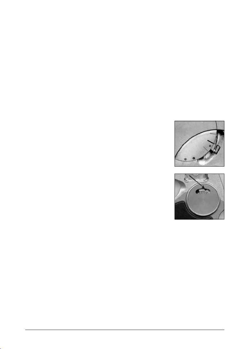
3. After removal of the cover plate check if the upper side of the Lever
Arm (holding the satellite cable) is parallel to the lower of the three
markers on the Function Unit (see Fig. 5).
4. Using a Phillips screwdriver, loosen the screw of the Service Hatch at
the back of the satellite and remove the cover and screw.
5. Use the Allen screwdriver to loosen the cone point safety screw two to
three turns and slide the Cable End Block of the inner cable (see Fig. 6).
6. Twist the Teon outer cable from the Swivel Connector at the bottom
of the satellite.Place the Swivel in one hand between your thumb
and forenger and the Teon outer cable in the other hand between
the thumb and forenger and unscrew (counterclockwise) the outer
cable from the Swivel Connector (see Fig. 7).Subtract the inner cable
outwards through the Swivel.
7. Loosen the Cone Point Safety Screw on the side of the joint, two turns
will do (see Fig. 8).Do not remove the screw from the joint.
8. Turn the Satellite Set Screw (which connects the Teon cable to the
joint) completely in the joint and then two complete turns up again.
9. NOTE: carve the Teon outer cable with a sharp knife to the desired
length and remove the excess outer cable (the inner steel cable will
be shortened in step 14).
Fig.1
Fig.2
Fig.3
Satellite Control
The patient needs to be instructed on functionality and how to operate the satellite.
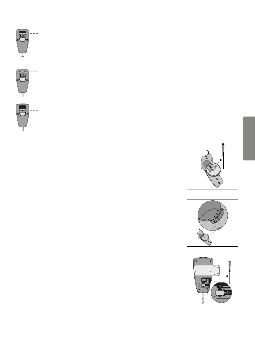
Mode 1 – Automatic Locking and Unlocking
The slider on the satellite is positioned in the middle.This is the normal position by which the SPL 2
joint automatically locks and unlocks during walking.In this mode, the joint can also be unlocked once,
by slightly pushing the switch upwards.The automatic mode is activated again when the joint is fully
extended.
Mode 2 – Permanently Unlocked
The slider on the satellite is slid upward from the center.In this mode the SPL 2 joint is permanently
unlocked.NOTE: When deactivating the permanent unlocking (by pushing the central button), the
satellite automatically shifts into the permanent locking mode and thus needs to be slid up into the
automatic locking/unlocking mode.
Mode 3 – permanently Locked
For this purpose the central button on the satellite is to be pressed for the slider to slid fully down.This
is a safety mode in which the SPL 2 joint is constantly locked (e.g. at home, making many turns, etc.).
Fig.4
Fig.5
Fig.6
Orthosis Construction
Basically any type of construction is suitable as long as sufcient torsion rigidity and a possibility of
changing the exion position during the initial tting is taken into account.
When the Joint is used in a Carbon ber reinforced Construction, the SPL 2 should be disassembled by
removing the Satellite – disconnect the cable within the Function Unit (H) and loosen the IQ set screws
(D), Loosen the adjustment screw and gently pull the cable from the housing.Now the Function Unit
(H) can be pushed inside and removed.
The SPC exion Control Unit has to be removed (E) and sealed with Stick Wax (Art. nr. 990035) to
prevent improper resin ow. In this case the Upright spacer can be used (Art. nr. 029860) and aligned,
allowing the Joints to be mounted in a later stage.
Joint Alignment
The Alignment Unit has to be parallel to the plumb line.The SPC Joint should not be aligned in full
extension.If the Joint is aligned without using the Unit the Cover Plates (B) may be removed allowing
the Joint axis to be used for parallel alignment.
Dynamic Initial Fitting
Function Check
Prior to the initial tting the proper setting of the Joint need to be checked
■The slotted arm of the Function Unit (H) must be set in neutral 0 position
(see picture) when the Satellite is in the 1st mode.Adjust with the
Proximal adjustment screw (F) on the SPL 2 is necessary.
■Can the SPL 2 Joint lock after swing with the Satellite in the 1st mode?
Adjusting locking and unlocking
Timing settings to lock or unlock can be read or adjusted by moving the
pendulum weight of the Function Unit.
■Moving the pendulum ANTERIOR (forward), DECREASES the tendency to
lock, because its weight is shifted forward.
■Moving the pendulum POSTERIOR (backward), INCREASES the tendency
to lock because its weight is shifted backward.
ENG
32
33
Swing Phase Lock 2Basko Healthcare
Basko Healthcare Swing Phase Lock 2
Shortening the Satellite Cable
First determine the position where the satellite will be mounted on the
thigh cuff of the orthosis in order to establish the correct cable length.
Bear in mind that the cable should have a slight S-shape.
1. Position the joint in full extension and set the satellite in Mode 3 by
pressing the button on the satellite (see Fig. 3).Make sure the joint
is indeed locked.
2. Use the supplied Allen screwdriver to loosen the two screws on the
medial (stainless steel) Cover Plate and remove it (see Fig. 4).
3. After removal of the cover plate check if the upper side of the Lever
Arm (holding the satellite cable) is parallel to the lower of the three
markers on the Function Unit (see Fig. 5).
4. Using a Phillips screwdriver, loosen the screw of the Service Hatch at
the back of the satellite and remove the cover and screw.
5. Use the Allen screwdriver to loosen the cone point safety screw two to
three turns and slide the Cable End Block of the inner cable (see Fig. 6).
6. Twist the Teon outer cable from the Swivel Connector at the bottom
of the satellite.Place the Swivel in one hand between your thumb
and forenger and the Teon outer cable in the other hand between
the thumb and forenger and unscrew (counterclockwise) the outer
cable from the Swivel Connector (see Fig. 7).Subtract the inner cable
outwards through the Swivel.
7. Loosen the Cone Point Safety Screw on the side of the joint, two turns
will do (see Fig. 8).Do not remove the screw from the joint.
8. Turn the Satellite Set Screw (which connects the Teon cable to the
joint) completely in the joint and then two complete turns up again.
9. NOTE: carve the Teon outer cable with a sharp knife to the desired
length and remove the excess outer cable (the inner steel cable will
be shortened in step 14).
Fig.1
Fig.2
Fig.3
Satellite Control
The patient needs to be instructed on functionality and how to operate the satellite.
Mode 1 – Automatic Locking and Unlocking
The slider on the satellite is positioned in the middle.This is the normal position by which the SPL 2
joint automatically locks and unlocks during walking.In this mode, the joint can also be unlocked once,
by slightly pushing the switch upwards.The automatic mode is activated again when the joint is fully
extended.
Mode 2 – Permanently Unlocked
The slider on the satellite is slid upward from the center.In this mode the SPL 2 joint is permanently
unlocked.NOTE: When deactivating the permanent unlocking (by pushing the central button), the
satellite automatically shifts into the permanent locking mode and thus needs to be slid up into the
automatic locking/unlocking mode.
Mode 3 – permanently Locked
For this purpose the central button on the satellite is to be pressed for the slider to slid fully down.This
is a safety mode in which the SPL 2 joint is constantly locked (e.g. at home, making many turns, etc.).
Fig.4
Fig.5
Fig.6
Orthosis Construction
Basically any type of construction is suitable as long as sufcient torsion rigidity and a possibility of
changing the exion position during the initial tting is taken into account.
When the Joint is used in a Carbon ber reinforced Construction, the SPL 2 should be disassembled by
removing the Satellite – disconnect the cable within the Function Unit (H) and loosen the IQ set screws
(D), Loosen the adjustment screw and gently pull the cable from the housing.Now the Function Unit
(H) can be pushed inside and removed.
The SPC exion Control Unit has to be removed (E) and sealed with Stick Wax (Art. nr. 990035) to
prevent improper resin ow. In this case the Upright spacer can be used (Art. nr. 029860) and aligned,
allowing the Joints to be mounted in a later stage.
Joint Alignment
The Alignment Unit has to be parallel to the plumb line.The SPC Joint should not be aligned in full
extension.If the Joint is aligned without using the Unit the Cover Plates (B) may be removed allowing
the Joint axis to be used for parallel alignment.
Dynamic Initial Fitting
Function Check
Prior to the initial tting the proper setting of the Joint need to be checked
■The slotted arm of the Function Unit (H) must be set in neutral 0 position
(see picture) when the Satellite is in the 1st mode.Adjust with the
Proximal adjustment screw (F) on the SPL 2 is necessary.
■Can the SPL 2 Joint lock after swing with the Satellite in the 1st mode?
Adjusting locking and unlocking
Timing settings to lock or unlock can be read or adjusted by moving the
pendulum weight of the Function Unit.
■Moving the pendulum ANTERIOR (forward), DECREASES the tendency to
lock, because its weight is shifted forward.
■Moving the pendulum POSTERIOR (backward), INCREASES the tendency
to lock because its weight is shifted backward.
ENG

34
35
Swing Phase Lock 2Basko Healthcare
Basko Healthcare Swing Phase Lock 2
IQ SPL 2 Joint
(Art.nr.: IQ210R or L)
■1 SPL 2 Joint
■1 Inner hexagonal wrench
■2 Stickers
■2 Cable Clamps
■2 Nyloplex stud with header
■1 Manual
IQ SPC Joint
(Art.nr.: IQ120R or L)
■1 SPC Joint
■1 Inner hexagonal wrench
■1 Manual
IQ Satellite
(Art.nr.: IQ141)
■1 Satellite and Cable
■1 Manual
Package contents
IQ Swing Phase Lock 2 Set
(Art.nr.: IQ200R or L)
■1 SPL 2 Joint
■1 SPC Joint
■1 Satellite and cable
■1 Inner hexagonal wrench
■2 Stickers
■2 Cable Clamps
■2 Nyloplex stud with header
■1 Manual
IQ Swing Phase Lock 2 monolateral
(Art.nr.: IQ250R or L)
■1 SPL 2 Joint
■1 Satellite and cable
■1 Inner hexagonal wrench
■2 Stickers
■2 Cable Clamps
■2 Nyloplex stud with header
■1 Manual
Once all the adjustments are done, the opening on the Function Unit must be re-sealed using
the IQ sticker. This reduces the likelihood of dirt and clothing bers getting in.
Checking all functions
All functions must be checked once again.
■Do all three modes on the satellite switch reliably?
■Can a reliable locking be achieved with free swing?
■Is the locking sufcient (is the cable to the satellite on the right length, is the inner cable in a neutral
position, in the 0 position)?
■Does the Joint unlock reliably after the back swing?
■Are the stops all again in position and does the Joint run without play and smoothly?
10. Now slide the inner cable through the bottom of the Swivel
Connector into the Satellite Housing and screw the Teon outer cable
onto the Swivel.Place the Swivel in one hand between your thumb
and forenger and the Teon cable in the other hand between the
thumb and forenger. Press and turn (clockwise) the two parts rmly
together (the Swivel is self-tapping).
11. Slide the Cable End Block back over the steel inner cable and position the
End Block back into the corresponding slot in the satellite (see Fig. 9).
12. Recheck the correct position (Mode 3) of the Lever Arm in the
Function Unit of the joint (see Fig. 5).
13. Tighten the Cone Point Safety screw of the Cable End Block rmly on
the inner cable.
14. Use a sharp cutter to cut off the excess inner cable at ± 5 mm above
the Cable End Block.
15. Install the Service Hatch back on the back of the satellite and reattach
the screw.
16. Slide the satellite switch into the Automatic Position (Mode 1) (see Fig. 1)
and check within the Function Unit of the joint if the top of the Lever Arm
has moved and now is parallel with the center marker (see Fig. 10).
17. Use the Satellite Set Screw (which connects the Teon cable to the
joint) to ne tune and adjust the position described in step 16.
18. Tighten the Cone Point Safety screw back in the joint (see Fig. 8).
19. Mount the medial Cover Plate back onto the joint and tighten the screws.
20. Loosen both screws on the front side of the Satellite Housing and
remove the Auxiliary Bracket.
21. Determine the exact position where the satellite is to be mounted
on the thigh cuff and contour the bracket if necessary.Mount the
Auxiliary Bracket on the brace and reattach the satellite using the
screws at the front again.
22. Use the provided Cable Clamps to attach the satellite cable in order
to ensure an optimal,
at resting the cable run against the thigh cuff of the orthosis.
Fig.10
Fig.9
Fig.7
Fig.8
ENG
36
37
Swing Phase Lock 2Basko Healthcare
Basko Healthcare Swing Phase Lock 2
Fig. Article number Unit Article Description
AIQ120L/R 1x Swing Phase Control Joint
BIQ120/03 1x Joint Cover Plate Set
B1IQ110/03/01 2x Cover Plate Screws
B2IQ120/03/02 1x Lateral Cover Plate
CIQ120/04 1x Axis Set
C1IQ120/04/01 1x Axis Set
C2IQ120/04/02 1x Female Ax
DIQ120/08 1x Collar Bearing Set
EIQ120/09 1x Flexion Control Set
E1IQ120/09/01 1x Flexion Control Bumper Pin
E2IQ120/09/02 1x Flexion Control Spring Nut
E3IQ120/09/03 1x Flexion Control Spring
B1
B
B2C2
C1
C
E1E2E3
E
D
A
Parts SPC Joint
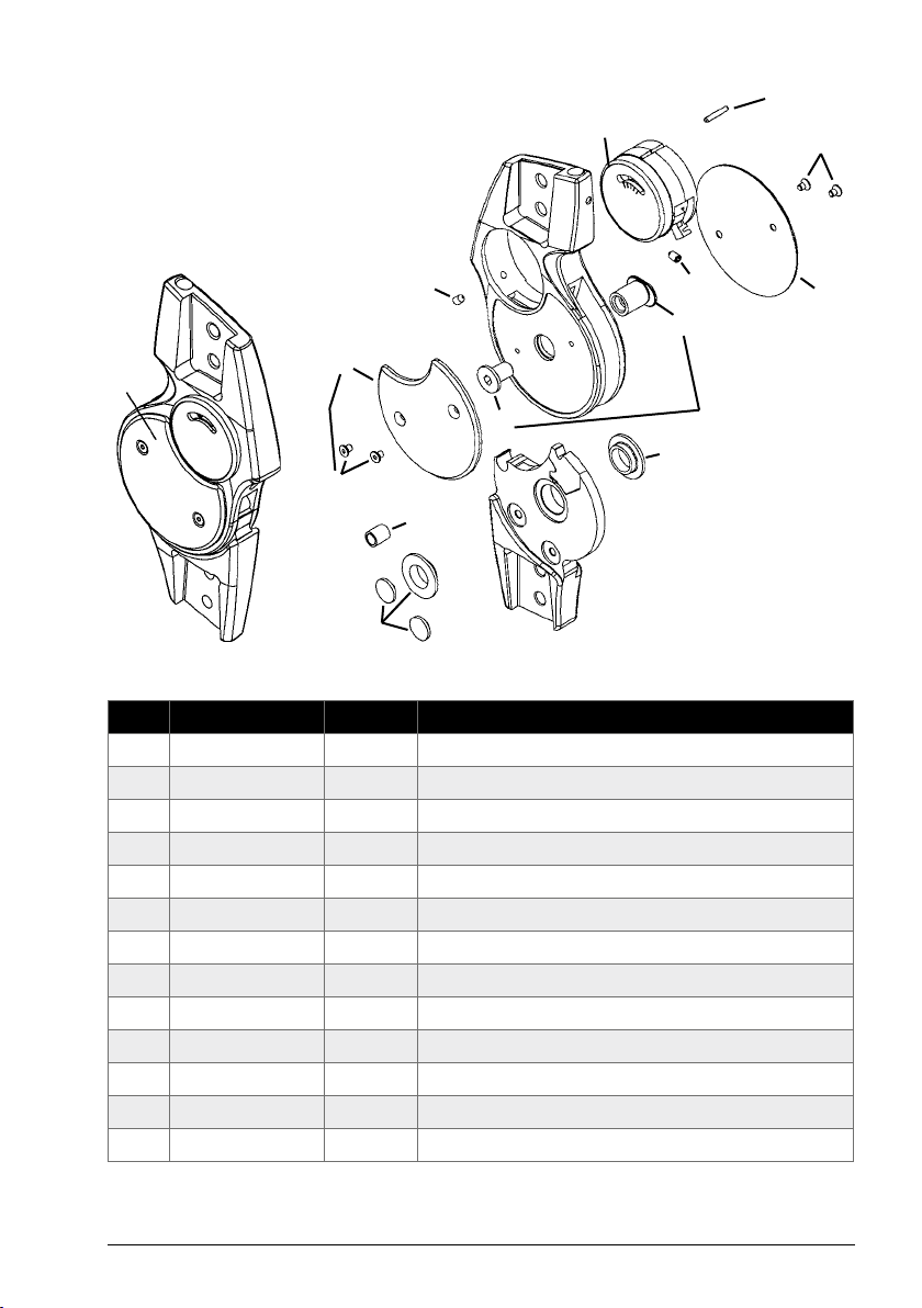
Fig. Article number Unit Article Description
AIQ210L or R 1x Swing Phase Lock 2 Joint
B IQ110/03 1x Joint Cover Plate Set
B1IQ110/03/01 4x Cover Plate Screws
B2IQ110/03/02 1x Medial Cover Plate
B3IQ110/03/03 1x Lateral Cover Plate
CIQ110/04 1x Axis Set
C1IQ110/04/01 1x Female Ax
C2IQ110/04/02 1x Male Ax
DIQ110/05 1x Cone Point Set Screw
E IQ210/07 1x Bumper
GIQ110/08 1x Collar Bearing Set
HIQ130L or R 1x Function Unit
IIQ130/01 1x Function Unit Spring Pin
A
G
E
B3
B
B1
C1
B1
B2
D
H
I
D
G
C
C2
Overview Parts
Parts SPL 2 Joint
ENG

36
37
Swing Phase Lock 2Basko Healthcare
Basko Healthcare Swing Phase Lock 2
Fig. Article number Unit Article Description
AIQ120L/R 1x Swing Phase Control Joint
BIQ120/03 1x Joint Cover Plate Set
B1IQ110/03/01 2x Cover Plate Screws
B2IQ120/03/02 1x Lateral Cover Plate
CIQ120/04 1x Axis Set
C1IQ120/04/01 1x Axis Set
C2IQ120/04/02 1x Female Ax
DIQ120/08 1x Collar Bearing Set
EIQ120/09 1x Flexion Control Set
E1IQ120/09/01 1x Flexion Control Bumper Pin
E2IQ120/09/02 1x Flexion Control Spring Nut
E3IQ120/09/03 1x Flexion Control Spring
B1
B
B2C2
C1
C
E1E2E3
E
D
A
Parts SPC Joint
Fig. Article number Unit Article Description
AIQ210L or R 1x Swing Phase Lock 2 Joint
B IQ110/03 1x Joint Cover Plate Set
B1IQ110/03/01 4x Cover Plate Screws
B2IQ110/03/02 1x Medial Cover Plate
B3IQ110/03/03 1x Lateral Cover Plate
CIQ110/04 1x Axis Set
C1IQ110/04/01 1x Female Ax
C2IQ110/04/02 1x Male Ax
DIQ110/05 1x Cone Point Set Screw
E IQ210/07 1x Bumper
GIQ110/08 1x Collar Bearing Set
HIQ130L or R 1x Function Unit
IIQ130/01 1x Function Unit Spring Pin
A
G
E
B3
B
B1
C1
B1
B2
D
H
I
D
G
C
C2
Overview Parts
Parts SPL 2 Joint
ENG
38
39
Swing Phase Lock 2Basko Healthcare
Basko Healthcare Swing Phase Lock 2
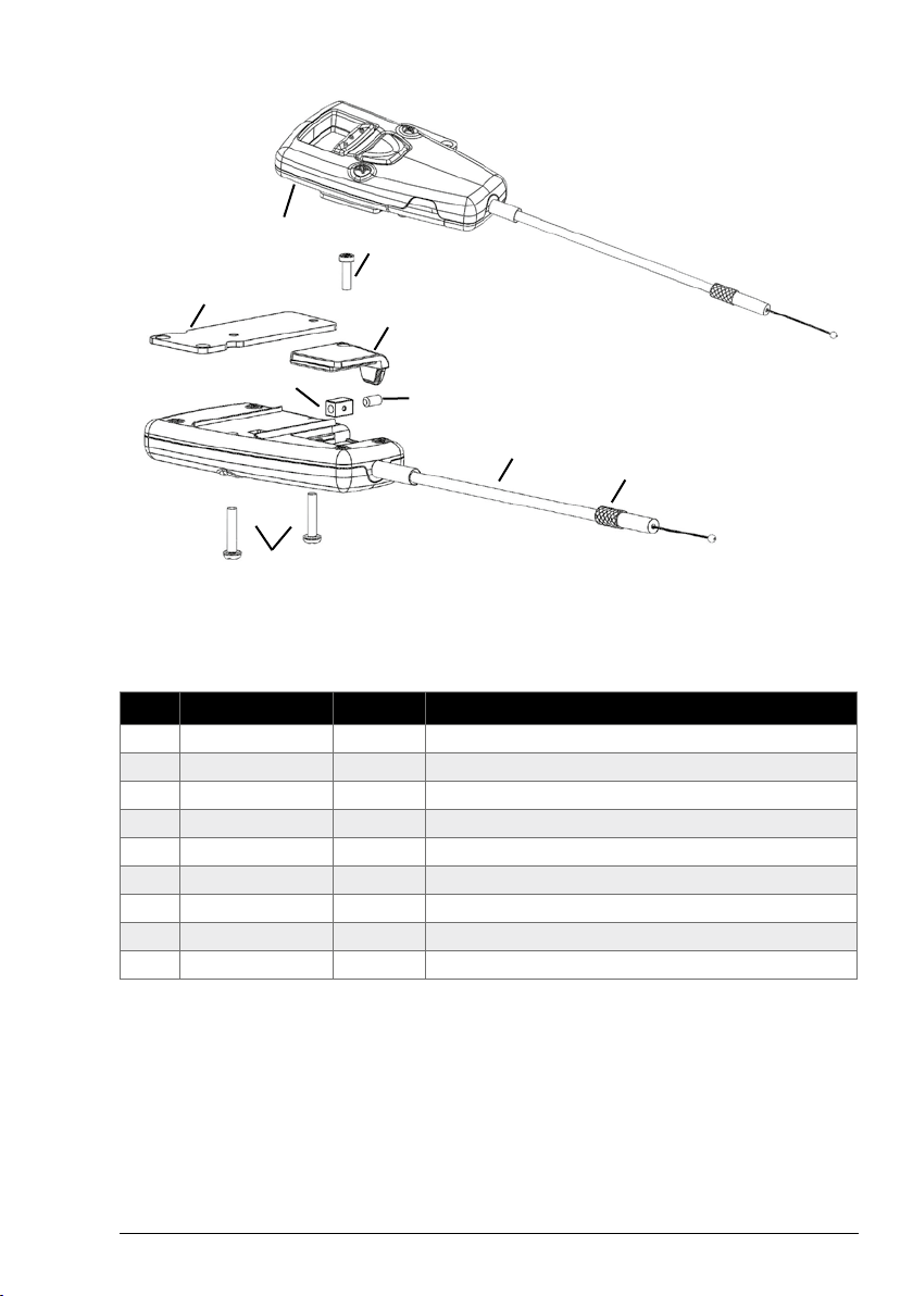
Parts Satellite
Fig. Article number Unit Article Description
AIQ141 1x IQ SPL Satellite complete
BIQ141/01 1x IQ SPL Satellite Service Hatch Screw 2,2 x 8 mm
CIQ141/02 1x IQ SPL Satellite Service Hatch
DIQ141/03 1x IQ SPL Satellite Mounting Bracket
EIQ141/04 1x IQ SPL Satellite Mounting Plate Screws 2,5 x 12 mm
FIQ140/04 1x IQ SPL Satellite Cable End Block
GIQ140/12 1x IQ Satellite Crater Set Screw for Cable end Block
HIQ141/05 1x IQ SPL Satellite Cable Set
IIQ140/06 1x IQ SPL Satellite Set Screw
A
C
B
D
I
H
E
FG
Consignes d’utilisation ........................................................ 40
Utilisation du produit/Indications .............................................. 40
Indications .............................................................. 40
Contre-indications ........................................................ 40
Propriétés fonctionnelles/autres conditions/zone de déploiement ................... 41
Fonctions .................................................................... 41
Propriétés techniques SPL 2 ................................................ 41
Propriétés techniques SPC .................................................. 41
Propriétés techniques Satellite .............................................. 41
Instructions de nettoyage/de désinfection ...................................... 42
Consignes d'entretien ........................................................ 42
Matériaux utilisés ............................................................ 42
Instructions d’installation et de montage ....................................... 42
Structure de l'orthèse ....................................................... 42
Prise des mesures ........................................................ 42
Construction des orthèses .................................................. 43
Alignement de la articulation ............................................... 43
Contrôle fonctionnel ...................................................... 43
Réglage activation du verrouillage et du déverrouillage .......................... 43
Fonctions satellites ....................................................... 44
Réduction du câble satellite ................................................ 44
Contrôle de toutes les fonctions ............................................... 46
Contenu de l'emballage ....................................................... 47
Aperçu des pièces ............................................................ 48
Éléments articulation SPL 2 ................................................. 48
Éléments articulation SPC .................................................. 49
Éléments Satellite ........................................................ 50
Français
FR

Gebruiksaanwijzing
Gebrauchsanleitung
Manual
Mode d’emploi
Swing Phase Lock 2
IQ88003 / Stand: 01/2018
Basko Healthcare
1505 HX Zaandam
Fax: +31 (0) 75 - 612 63 73
Internet: www.basko.com
Pieter Lieftinckweg 16
Tel.: +31 (0) 75 - 613 15 13
E-mail: verkoop@basko.com
BASKO HEALTHCARE
P. Lieftinckweg 16
NL 1505 HX Zaandam
Tel.: +31 75 613 15 13
Other manuals for Swing Phase Lock 2
1
This manual suits for next models
1
Table of contents
Other Basko Healthcare Personal Care Product manuals


