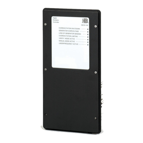
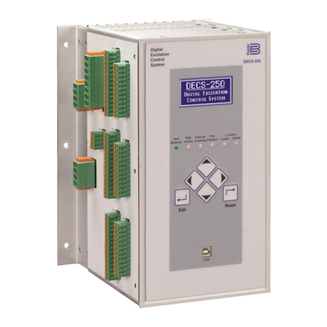
Basler DECS-250 User manual

12570 Route 143 •Highland, Illinois 62249-1074 USA
Tel +1 618.654.2341 •Fax +1 618.654.2351
Publication
9440300990 Rev S
January 2020
DECS-250
Digital Excitation Control System
Instruction Manual

WARNING: California's Proposition 65 requires special warnings for
products that may contain chemicals known to the state of California to
cause cancer, birth defects or other reproductive harm. Please note that
by posting this Proposition 65 warning, we are notifying you that one or
more of the Proposition 65 listed chemicals may be present in products
we sell to you. For more information about the specific chemicals found
in this product, please visit https://www.basler.com/Prop65.

9440300990 i
DECS-250 Preface
Preface
This instruction manual provides information about the installation and operation of the DECS-250 Digital
Excitation Control System. To accomplish this, the following information is provided:
•General Information
•Human-machine interface
•Functional description
•Installation
•BESTCOMSPlus®software
•Setup
•Communication protocols
•Maintenance
•Specifications
•Expansion modules
Conventions Used in this Manual
Important safety and procedural information is emphasized and presented in this manual through
warning, caution, and note boxes. Each type is illustrated and defined as follows.
Warning!
Warning boxes call attention to conditions or actions that may cause
personal injury or death.
Caution
Caution boxes call attention to operating conditions that may lead to
equipment or property damage.
Note
Note boxes emphasize important information pertaining to installation
or operation.
Note
Be sure that the device is hard-wired to earth ground with no smaller
than 12 AWG (3.3 mm2) copper wire attached to the case ground
terminal. When the device is configured in a system with other
devices, a separate lead should be connected from the ground bus to
each device.
Current transformer (CT) grounding should be applied in accordance
with local codes and conventions.

ii 9440300990
Preface DECS-250
12570 State Route 143
Highland IL 62249-1074 USA
www.basler.com
info@basler.com
Tel: +1 618.654.2341
Fax: +1 618.654.2351
© 2020 by Basler Electric
All rights reserved
First printing: October 2012
Warning!
READ THIS MANUAL. Read this manual before installing, operating, or maintaining the DECS-250.
Note all warnings, cautions, and notes in this manual as well as on the product. Keep this manual with
the product for reference. Only qualified personnel should install, operate, or service this system.
Failure to follow warning and cautionary labels may result in personal injury or property damage.
Exercise caution at all times.
Basler Electric does not assume any responsibility to compliance or noncompliance with national code, local code,
or any other applicable code. This manual serves as reference material that must be well understood prior to
installation, operation, or maintenance.
For terms of service relating to this product and software, see the Commercial Terms of Products and Services
document available at www.basler.com/terms.
This publication contains confidential information of Basler Electric Company, an Illinois corporation. It is loaned for
confidential use, subject to return on request, and with the mutual understanding that it will not be used in any
manner detrimental to the interests of Basler Electric Company and used strictly for the purpose intended.
It is not the intention of this manual to cover all details and variations in equipment, nor does this manual provide
data for every possible contingency regarding installation or operation. The availability and design of all features
and options are subject to modification without notice. Over time, improvements and revisions may be made to this
publication. Before performing any of the following procedures, contact Basler Electric for the latest revision of this
manual.
The English-language version of this manual serves as the only approved manual version.

9440300990 iii
DECS-250 Preface
This product contains, in part, open source software (software licensed in a way that ensures freedom to run,
copy, distribute, study, change, and improve the software) and you are granted a license to that software under the
terms of either the GNU General Public License or GNU Lesser General Public License. The licenses, at the time
of sale of the product, allow you to freely copy, modify, and redistribute that software and no other statement or
documentation from us, including our End User License Agreement, places any additional restrictions on what you
may do with that software.
For at least three (3) years from the date of distribution of this product, a machine-readable copy of the complete
corresponding source code for the version of the programs distributed to you will be sent upon request (contact
information is provided above). A fee of no more than our cost of physically performing the source code distribution
is charged.
The source code is distributed in the hope that it will be useful, but WITHOUT ANY REPRESENTATION or
WARRANTY or even the implied warranty of MERCHANTABILITY or FITNESS FOR A PARTICULAR PURPOSE.
Refer to the source code distribution for additional restrictions regarding warranty and copyrights.
For a complete copy of GNU GENERAL PUBLIC LICENSE Version 2, June 1991 or GNU LESSER GENERAL
PUBLIC LICENSE Version 2.1, February 1999 refer to www.gnu.org or contact Basler Electric. You, as a Basler
Electric Company customer, agree to abide by the terms and conditions of GNU GENERAL PUBLIC LICENSE
Version 2, June 1991 or GNU LESSER GENERAL PUBLIC LICENSE Version 2.1, February 1999, and as such
hold Basler Electric Company harmless related to any open source software incorporated in this product. Basler
Electric Company disclaims any and all liability associated with the open source software and the user agrees to
defend and indemnify Basler Electric Company, its directors, officers, and employees from and against any and all
losses, claims, attorneys' fees, and expenses arising from the use, sharing, or redistribution of the software.
Review the software website for the latest version of the software documentation.
Portions of this software are copyright © 2014 The Free Type Project (www.freetype.org). All rights reserved.

iv 9440300990
Preface DECS-250

9440300990 v
DECS-250 Revision History
Revision History
A historical summary of the changes made to this instruction manual is provided below. Revisions are
listed in reverse chronological order.
Visit www.basler.com to download the latest hardware, firmware, and BESTCOMSPlus®revision
histories.
Instruction Manual Revision History
Manual
Revision and Date
Change
S, Jan-20
•Added support for BESTCOMSPlus version 4.01.00.
•Removed Rev Letter from all pages
•Changed sequential numbering to sectional numbering
•Moved Instruction Manual Revision History into Preface
•Removed standalone Revision History chapter
•Added pre-position traverse rate settings.
•Corrected field overcurrent reset equation.
•Added description for Phase Rotation Mismatch alarm.
•Clarified that three-phase current sensing is required for PSS.
•Added Gen to Bus PT Match Level equation.
•Changed “Generator” to “Machine” in Figures 19-1, 19-2, and 19-3.
•Minor text edits throughout manual
R, Apr-19
•Added support for firmware version 1.06.00 and BESTCOMSPlus
version 3.21.00
•Added drawings for Analog Inputs – Current Input Connections in the
Analog Expansion Module chapter
•
Minor text edits throughout manual
Q
•This revision letter not used
P, Nov-18
•Added California Proposition 65 warning statement
•Clarified power system stabilizer type
O
•
This revision letter not used
N, Jun-18
•Added Configuration Mismatch Delay setting in Regulation chapter.
•Corrected caution box in Power Inputs chapter.
•Added UL, Class I, Div. 2 for AEM-2020 and CEM-2020.
•Improved description of CEM-2020 output contact ratings.
•Added caution statement about using the 40Q function with a rated
PF of 1.0.
•Removed Table 4. Lead/Lag labels remain the same in generator
and motor modes.
•Corrected description of settings under Frequency Correction section
in Synchronizer chapter.
•Corrected V/Hz Limiter description and Figure 55 (Typical 1.1 pu
Volts per Hertz Limiter Curve) in Limiters chapter.
•Corrected UEL, Real Power Exponent setting range in Limiters
chapter.
•Added notes in Typical Connections chapter about the terminating
resistor requirement for CAN terminals.
M, May-18
•Maintenance release
L, Sept-17
•Added support for BESTCOMSPlus version 3.17.01.

vi 9440300990
Revision History DECS-250
Manual
Revision and Date
Change
K, May-17
•Changed the Auto Save interval to 10 minutes in the Regulation
chapter.
•Added Loss of Sensing Trip Criteria table to the Protection chapter.
•Clarified description of Summing Point OEL online operation in the
Limiters chapter.
•Added support for synchronizing at 25 Hz.
•Added caution statement for operation in caustic environments to the
Mounting chapter.
•Noted the location of the USB driver directory in the
BESTCOMSPlus Software chapter.
•Added nonvolatile memory caution statement to the BESTlogicPlus,
Communication, Modbus Communication, and Profibus
Communication chapters.
•Clarified Step 4 under Setup in Profibus Communication chapter.
•Added Active Setpoint registers (instance 254) to the Profibus
Communication chapter.
•Added USB driver installation troubleshooting material to the
Maintenance chapter.
•Simplified the presentation of the sensing voltage nominal input
ranges, added metering accuracy values, and added self-tuning
patent number to the Specifications chapter.
•Added description of the status LED on the AEM-2020 and
CEM-2020 to their respective chapters.
•Updated CE Compliance and UL Certification sections in
Specifications, Analog Expansion Module, and Contact Expansion
Module chapters.
•
Minor text edits throughout manual
J, May-15
•Improved description of optional escutcheon plate in the Mounting
chapter
•Added a figure for station-powered applications in the Typical
Connections chapter.
•Updated manual to reflect BESTCOMSPlus screen layout changes
•Added Offline Logic Simulator description in the BESTlogicPlus
chapter
•Added descriptions for Cursors Enabled and Sync Graph Scrolling
settings on the Analysis Options screen in the Testing chapter
•Added EAC certification in the Specifications chapter
•Minor text edits throughout manual
I
•This revision letter not used

9440300990 vii
DECS-250 Revision History
Manual
Revision and Date
Change
H, Feb-15
•Added support for DECS-250 firmware version 1.03.00 and
BESTCOMSPlus version 3.08.00
•Changed layout of Auxiliary Control Gains section and added
equations in the Auxiliary Control chapter
•Added Off-Page Objects description in the BESTlogicPlus chapter
•Cleaned up various Modbus register names and descriptions in the
Modbus chapter
•Added Modbus registers for AEM Configuration, AEM Protection,
RTD Protection, and Thermocouple Protection in the Modbus
chapter
•Expanded IRIG specifications in the Specifications chapter
•Added Maritime Recognition to the Specifications chapter
•
Minor text edits throughout manual
G, Aug-14
•Increased maximum operating temperature to +70°C
•Added GND terminal to power connector and vent holes to chassis
F, Apr-14
•Added Russian language support
•Added overexcitation (24) protection
•Added transient excitation boosting function
•Added loss of excitation (40Q) protection for motors
•Added integrating reset method to takeover OEL
•Added angle compensation to synchronizer and sync check (25)
•Increased available real-time monitoring plots from two to six
•
Minor text edits throughout manual
E, Dec-13
•Improved description of Profibus communication setup
•Expansion modules, AEM-2020 and CEM-2020, now have
connectors with gold-plated pins to better protect communication
signal integrity
•Added PF Active Power Level setting for var/PF regulation
•Added Network Load Share ID settings
•Added secure login via Modbus™ communication settings
•Added Binary Points and Metering Modbus registers
•
Minor text edits throughout manual

viii 9440300990
Revision History DECS-250
Manual
Revision and Date
Change
D, Jul-13
•Added maritime agency recognitions (BV, DNV, GL)
•Clarified online OEL and low-level SCL limiting conditions
•Improved the description of the BESTCOMSPlus®control panel
setpoint window
•Added field wiring requirement for EMC compliance
•Improved typical connection diagrams
•Improved firmware upgrading procedures
•Added BESTlogic™Plus logic element “27”
•Added clarification stating that the PARALLEL_EN logic input must
be true in order for UEL and droop compensation to operate
•Expanded description of the Loss of Excitation (40Q) protection
element
•Expanded description of the IRIG decoding setting in Clock Setup
•Minor edits to Modbus™ communication legacy register table
•Added caution statements in several places recommending proper
grounding of the DECS-250 when using the non-isolated USB port
C, Nov-12
•Updated operating temperature and frequency specifications
B, Oct-12
•Initial release

9440300990 ix
DECS-250 Contents
Contents
Introduction................................................................................................................................................. 1-1
Controls and Indicators .............................................................................................................................. 2-1
Power Inputs .............................................................................................................................................. 3-1
Power Stage............................................................................................................................................... 4-1
Voltage and Current Sensing ..................................................................................................................... 5-1
Synchronizer .............................................................................................................................................. 6-1
Regulation .................................................................................................................................................. 7-1
Auxiliary Control ......................................................................................................................................... 8-1
Contact Inputs and Outputs ....................................................................................................................... 9-1
Protection ................................................................................................................................................. 10-1
Limiters..................................................................................................................................................... 11-1
Grid Code ................................................................................................................................................. 12-1
Metering ................................................................................................................................................... 13-1
Event Recorder ........................................................................................................................................ 14-1
Power System Stabilizer .......................................................................................................................... 15-1
Stability Tuning......................................................................................................................................... 16-1
Mounting................................................................................................................................................... 17-1
Terminals and Connectors ....................................................................................................................... 18-1
Typical Connections................................................................................................................................. 19-1
BESTCOMSPlus®Software ..................................................................................................................... 20-1
BESTlogic™Plus...................................................................................................................................... 21-1
Communication ........................................................................................................................................ 22-1
Configuration ............................................................................................................................................ 23-1
Security .................................................................................................................................................... 24-1
Timekeeping............................................................................................................................................. 25-1
Testing...................................................................................................................................................... 26-1
CAN Communication................................................................................................................................ 27-1
Modbus® Communication........................................................................................................................ 28-1
PROFIBUS Communication..................................................................................................................... 29-1
Maintenance............................................................................................................................................. 30-1
Specifications ........................................................................................................................................... 31-1
Analog Expansion Module ....................................................................................................................... 32-1
Contact Expansion Module ...................................................................................................................... 33-1

x 9440300990
Contents DECS-250

9440300990 1-1
DECS-250 Introduction
1 • Introduction
DECS-250 Digital Excitation Control Systems offer precise excitation control and machine protection in a
compact package. DECS-250 adaptability to many applications is assured through configurable contact
inputs and outputs, flexible communication capabilities, and programmable logic implemented with the
provided BESTCOMSPlus®software.
Features and Functions
DECS-250 features and functions include:
•Precise excitation control for synchronous generator or synchronous motor applications
oPower factor and var metering values will be opposite in motor mode
•Five excitation control modes:
oAutomatic Voltage Regulation (AVR)
oField Current Regulation (FCR)
oField Voltage Regulation (FVR)
oPower Factor Regulation (PF)
oVar Regulation (var)
•Three pre-position setpoints for each excitation control mode
•Internal tracking between operating mode setpoints and external tracking of a second DECS
excitation setpoint
•Two PID stability groups with Auto Tune feature
•Remote setpoint control input accepts analog voltage or current control signal
•Grid code functions
oConnect and disconnect
oActive power control
oReactive power control
•Real-time metering
•Optional automatic synchronizer
•Optional integrated power system stabilizer (IEEE Std 421.5 type PSS2A/2B/2C)
oGenerator or motor control modes, accommodates phase rotation changes between
modes
oSpeed and power sensing or speed-only sensing
oTwo wattmeter or three-wattmeter methods of power measurement
•Soft start and voltage buildup control
•Five limiting functions:
oOverexcitation: summing point and takeover
oUnderexcitation
oStator current
oReactive power (var)
oUnderfrequency
•Twenty protection functions:
oGenerator undervoltage (27)
oGenerator overvoltage (59)
oLoss of sensing (LOS)
oOverfrequency (81O)
oUnderfrequency (81U)
oReverse power (32R)
oLoss of excitation (40Q)
oField overvoltage
oField overcurrent
oLoss of PMG
oExciter diode failure
oSync-check (25)
oEight configurable protection elements

1-2 9440300990
Introduction DECS-250
•IRIG or network time synchronization
•Sixteen contact sensing inputs
oTwo fixed-function inputs: Start and Stop
oFourteen programmable inputs
•Twelve contact outputs
oOne, fixed-function output: Watchdog (SPDT configuration)
oEleven programmable outputs
•Flexible communication
oSerial communication through front-panel USB port
oModbus communication through RS-485 port or Modbus TCP
oEthernet communication through an optional copper or fiber optic port
oCAN communication with an ECU (engine control unit), optional AEM-2020 Analog
Expansion Module, or optional CEM-2020 Contact Expansion Module
oOptional PROFIBUS communication protocol
•Data logging, sequence of events recording, and trending
•Optional CEM-2020 Contact Expansion Module provides:
oTen contact inputs
oEighteen contact outputs (CEM-2020H) or 24 contact outputs (CEM-2020)
oCustomizable input and output functions assigned through BESTlogic™Plus
programmable logic
oCommunication via CAN protocol
•Optional AEM-2020 Analog Expansion Module provides:
oEight analog inputs
oEight resistive thermocouple device (RTD) inputs
oTwo thermocouple inputs
oFour analog outputs
oCustomizable input and output functions assigned through BESTlogicPlus programmable
logic
oCommunication via CAN protocol
Applications
The DECS-250 is intended for synchronous generator or synchronous motor applications. The DECS-250
controls the machine output through the application of regulated DC excitation power to the exciter field.
The level of excitation power is based on the monitored voltage and current, and a regulation setpoint
established by the user. The operating mode, generator or motor, is changed on the Operating Mode
settings screen. Power factor and var metering values will be opposite in motor mode.
Excitation power is supplied from the DECS-250 by means of a filtered, switching power module that uses
pulse-width modulation. It is capable of supplying 15 Adc (or 20 Adc up to 55°C (131°F)) continuously at a
nominal voltage of 32, 63, or 125 Vdc. With nominal operating power applied, it has a forcing capability of
30 Adc for 10 seconds.
Package
A single, compact package contains all excitation control and power components.
A front panel HMI provides local annunciation and control through a backlit liquid crystal display (LCD),
light-emitting diodes (LEDs), and pushbuttons. Remote annunciation and control is provided through a
flexible communication interface which accommodates Ethernet, Modbus, optional PROFIBUS, and the
optional Interactive Display Panel (IDP-801).

9440300990 1-3
DECS-250 Introduction
Optional Features and Capabilities
DECS-250 optional features and capabilities are defined by a combination of letters and numbers that
make up the style number. The model number and style number describe options and characteristics in a
specific device and appear on a label affixed to the device.
Style Number
The style number identification chart in Figure 1 defines the electrical characteristics and operational
features available in the DECS-250.
Figure 1-1. DECS-250 Style Chart
Storage
If a DECS-250 will not be placed in service right away, store it in the original shipping carton in a
moisture- and dust-free environment. The temperature of the storage environment must be within the
range of –40 to 85°C (–40 to 185°F).
Electrolytic Capacitor Considerations
The DECS-250 contains long-life aluminum electrolytic capacitors. For a DECS-250 kept in storage as a
spare, the life of these capacitors can be maximized by energizing the device for 30 minutes once per
year. Refer to the energizing procedures provided in Maintenance.
When energizing the DECS-250 from a low impedance source (such as a wall outlet), use of an Inrush
Current Reduction Module (ICRM) is recommended to prevent damage to the DECS-250. For a detailed
description of the Inrush Current Reduction Module, refer to Basler publication 9387900990. ICRM
connections are illustrated in Typical Connections.

1-4 9440300990
Introduction DECS-250

9440300990 2-1
DECS-250 Controls and Indicators
2 • Controls and Indicators
All controls and indicators are located on the front panel and consist of pushbuttons, LED indicators, and
a liquid-crystal display (LCD).
Front Panel Illustration and Description
DECS-250 controls and indicators are illustrated in Figure 2-1 and described in Table 2-1. The locators
and descriptions of Table 2-1 correspond to the locators shown in Figure 2-1.
Figure 2-1. Front Panel Controls and Indicators

2-2 9440300990
Controls and Indicators DECS-250
Table 2-1. Front Panel Control and Indicators Descriptions
Locator
Description
A
Display. The liquid crystal display (LCD) serves as a local source of information
provided by the DECS-250. The LCD displays operating setpoints, loop gains,
metering, protection functions, system parameters, and general settings. The 128 by
64 dot pixel, backlit LCD displays white characters on a blue background.
B
Pre-Position Indicator. This red light emitting diode (LED) lights when the active mode
setpoint is at any of the three pre-position (predefined) settings.
C
Limit Indicators. Two red LEDs indicate when the active mode setpoint reaches the
minimum or maximum value.
D
Scrolling Pushbuttons. These four buttons are used to scroll up, down, left, and right
through the menus displayed on the LCD (locator A). During an editing session, the
left and right scrolling pushbuttons select the variable to be changed and the up and
down scrolling pushbuttons change the value of the variable.
E
Reset Pushbutton. This button cancels editing sessions, resets alarm annunciations
and latched alarm relays, and can be used for quick access to the metering screen.
F
Communication Port. This type B USB jack connects the DECS-250 with a PC
operating BESTCOMSPlus®for local communication. BESTCOMSPlus is supplied
with the DECS-250.
G
Edit Pushbutton. Pressing this button starts an editing session and enables changes to
DECS-250 settings. At the conclusion of the editing session, the Edit pushbutton is
pressed to save the settings changes.
H
Null Balance Indicator. This green LED lights when the setpoint of the inactive
operating modes (AVR, FCR, FVR, var, and PF) match the setpoint of the active
mode.
I
PSS Active Indicator. This red LED lights when the integrated power system stabilizer
is enabled and can generate a stabilizing signal in response to a power system
disturbance.
J
Internal Tracking Indicator. This red LED lights when any inactive mode (AVR, FCR,
FVR, Var, or Power Factor) is tracking the setpoint of the active mode to achieve a
“bumpless” transfer when changing active modes.
Menu Navigation
The DECS-250 provides local access to DECS-250 settings and metering values through a menu
structure displayed on the front panel LCD. An overview of the menu structure is illustrated in Figure 2-2.
Movement through the menu structure is achieved by pressing the four scrolling pushbuttons.

9440300990 2-3
DECS-250 Controls and Indicators
Figure 2-2. Menu Structure Overview
Adjusting Settings
A setting adjustment is made at the front panel by performing the following steps.
1. Navigate to the screen listing the setting to be changed.
2. Press the Edit button and enter the appropriate username and password to gain the needed level
of security access. (Information about implementing and using username and password
protection is provided in the Security chapter of this manual.)
3. Highlight the desired setting and press the Edit button to view the setting editing screen. This
screen lists the setting range or the permissible setting selection.
4. Use the scrolling pushbuttons to select the setting digits/selections and adjust/change the setting.
5. Press the Edit button to save the change.
Display Setup
BESTCOMSPlus Navigation Path: Settings Explorer, General Settings, Front Panel HMI
HMI Navigation Path: Settings, General Settings, Front Panel HMI
Front panel display appearance and behavior can be customized to meet user preferences and site
conditions. These BESTCOMSPlus settings are illustrated in Figure 2-3.
LCD
LCD setup includes a contrast adjustment to suit the viewing angle used or compensate for
environmental conditions. The ability to reverse the display colors is provided to accommodate lighting
conditions and user preferences.
Sleep Mode
Sleep mode reduces the demand on control power by turning off the LCD backlight when no pushbutton
activity is seen for the duration of the LCD Backlight Timeout setting.
Language
Language modules are available for the DECS-250. Once a language module is implemented it can be
enabled via the Language Selection setting.
Screen Scrolling
The display can be set to automatically scroll through a user-selected list of metered values. This feature
is enabled and disabled with the Enable Scroll setting. The rate at which scrolling occurs is configured
with the Scroll Time Delay setting.

2-4 9440300990
Controls and Indicators DECS-250
Figure 2-3. Front Panel HMI Settings
Other manuals for DECS-250
3
Table of contents
Other Basler Control System manuals