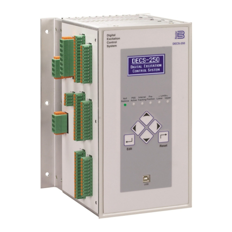
Basler DECS-150 User manual

12570 Route 143 •Highland, Illinois 62249-1074 USA
Tel +1 618.654.2341 •Fax +1 618.654.2351
Publication
9492600990 Rev H
Sep 2021
DECS-150
Digital Excitation Control System
Instruction Manual

WARNING: California's Proposition 65 requires special warnings for products that
may contain chemicals known to the state of California to cause cancer, birth defects or
other reproductive harm. Please note that by posting this Proposition 65 warning, we are
notifying you that one or more of the Proposition 65 listed chemicals may be present in
products we sell to you. For more information about the specific chemicals found in this
product, please visit https://www.basler.com/Prop65.

Digital Excitation Control System i
DECS-150 Preface
Preface
This instruction manual provides information about the installation and operation of the DECS-150. To
accomplish this, the following information is provided:
•General information
•Functional description
•Installation and connections
•BESTCOMSPlus®software
•Communication and configuration
•Testing and troubleshooting
•Specifications
Conventions Used in this Manual
Important safety and procedural information is emphasized and presented in this manual through
warning, caution, and note boxes. Each type is illustrated and defined as follows.
Warning!
Warning boxes call attention to conditions or actions that may cause
personal injury or death.
Caution
Caution boxes call attention to operating conditions that may lead to
equipment or property damage.
Note
Note boxes emphasize important information pertaining to installation
or operation.

ii Digital Excitation Control System
Preface DECS-150
12570 State Route 143
Highland IL 62249-1074 USA
www.basler.com
info@basler.com
Tel: +1 618.654.2341
Fax: +1 618.654.2351
© 2021 by Basler Electric
All rights reserved
First printing: September 2015
Warning!
READ THIS MANUAL. Read this manual before installing, operating, or maintaining
this equipment. Note all warnings, cautions, and notes in this manual as well as on the
product. Keep this manual with the product for reference. Only qualified personnel
should install, operate, or service this system. Failure to follow warning and cautionary
labels may result in personal injury or property damage. Exercise caution at all times.
Caution
Installing previous versions of firmware may result in compatibility issues causing the
inability to operate properly and may not have the enhancements and resolutions to
issues that more recent versions provide. Basler Electric highly recommends using the
latest version of firmware at all times. Using previous versions of firmware is at the
user’s risk and may void the warranty of the unit.
Basler Electric does not assume any responsibility to compliance or noncompliance with national
code, local code, or any other applicable code. This manual serves as reference material that
must be well understood prior to installation, operation, or maintenance.
For terms of service relating to this product and software, see the Commercial Terms of
Products and Services document available at www.basler.com/terms.
This publication contains confidential information of Basler Electric Company, an Illinois
corporation. It is loaned for confidential use, subject to return on request, and with the mutual
understanding that it will not be used in any manner detrimental to the interests of Basler Electric
Company and used strictly for the purpose intended.
It is not the intention of this manual to cover all details and variations in equipment, nor does this
manual provide data for every possible contingency regarding installation or operation. The
availability and design of all features and options are subject to modification without notice. Over
time, improvements and revisions may be made to this publication. Before performing any of the
following procedures, contact Basler Electric for the latest revision of this manual.
The English-language version of this manual serves as the only approved manual version.

Digital Excitation Control System iii
DECS-150 Revision History
Revision History
A historical summary of the changes made to this instruction manual is provided below. Revisions are
listed in reverse chronological order.
Visit http://www.basler.com to download the latest hardware, firmware, and BESTCOMSPlus®revision
histories.
Instruction Manual Revision History
Manual
Revision and Date
Change
H, Sep 2021
•Adjusted all front panel illustrations to show updated LED labeling
•Added clarification about the DECS-150 sensing and responding to
rms voltage
•Corrected explanation of the exciter diode monitor’s ripple
calculation
•Corrected the DECS-150’s breaker shunt trip output rating
•Added grid code and UKCA compliance statements
•Added caution statement about downgrading DECS-150 firmware
•Corrected unit of measure used by the stator current limiter
G, Jan 2021
•Added description of Tracking Comms Loss alarm
•
Added description of Auto Transfer Enable logic block
F, Apr 2020
•Added Figure 17-4, Typical Connections for motor applications
•Added note about time settings in Timekeeping section
•Added register 1230, Field Voltage Meter, in the Modbus
Communication section
•
Minor text edits throughout manual
E, Sep 2019
•Added support for firmware version 2.04.00 and BESTCOMSPlus
version 4.00.00
•Removed Rev Letter from all pages
•Changed sequential numbering to sectional numbering
•Moved Instruction Manual Revision History into Preface
•Removed standalone Revision History section
D, Apr 2019
•Added support for firmware version 2.03.00 and BESTCOMSPlus
version 3.21.00
•
Minor text edits throughout manual
C1, Oct 2018
•Added California Proposition 65 warning on back of cover page
C, Jan 2018
•Added information on external tracking, network load sharing, and
Modbus
•Added description of Underfrequency Limiter Reset Time setting
B, Mar 2017
•Added caution statement about nonvolatile memory
•Added power dissipation and maximum elevation specifications
•Added manual USB driver installation instructions
•Clarified current-sensing requirements for PSS operation
•Corrected description of online OEL operation

iv Digital Excitation Control System
Revision History DECS-150
Manual
Revision and Date
Change
A, Jul 2016
•Added information on the backup battery for the real-time clock
•Updated connections for Programmable Contact Inputs in the
Typical Connections section
•Added Ethernet Setup in the Communications section
•Updated Generator and Bus Voltage Sensing Ranges in the
Specifications section
•Added Ingress Protection Ratings in the Specifications section
•Updated Maritime Recognition specifications
•Minor text edits throughout manual
―, Sep 2015
•Initial release

Digital Excitation Control System v
DECS-150 Contents
Contents
Introduction................................................................................................................................................. 1-1
Front Panel................................................................................................................................................. 2-1
Power Input and Outputs ........................................................................................................................... 3-1
Voltage and Current Sensing ..................................................................................................................... 4-1
Regulation .................................................................................................................................................. 5-1
Auxiliary Control ......................................................................................................................................... 6-1
Contact Inputs and Outputs ....................................................................................................................... 7-1
Protection ................................................................................................................................................... 8-1
Limiters....................................................................................................................................................... 9-1
Grid Code ................................................................................................................................................. 10-1
Metering ................................................................................................................................................... 11-1
Reports..................................................................................................................................................... 12-1
Power System Stabilizer .......................................................................................................................... 13-1
Stability Tuning......................................................................................................................................... 14-1
Mounting................................................................................................................................................... 15-1
Terminals and Connectors ....................................................................................................................... 16-1
Typical Connections................................................................................................................................. 17-1
BESTCOMSPlus®Software ..................................................................................................................... 18-1
BESTlogic™Plus ....................................................................................................................................... 19-1
Communication ........................................................................................................................................ 20-1
Configuration ............................................................................................................................................ 21-1
Security .................................................................................................................................................... 22-1
Timekeeping............................................................................................................................................. 23-1
Testing...................................................................................................................................................... 24-1
Modbus Communication .......................................................................................................................... 25-1
Maintenance............................................................................................................................................. 26-1
Troubleshooting ....................................................................................................................................... 27-1
Specifications ........................................................................................................................................... 28-1
BESTCOMSPlus®Settings Loader Tool .................................................................................................. 29-1

vi Digital Excitation Control System
Contents DECS-150

9492600990 1-1
DECS-150 Introduction
1 • Introduction
DECS-150 Digital Excitation Control Systems offer precise excitation control and machine protection in a
compact package. DECS-150 adaptability to many applications is assured through configurable contact
inputs and outputs, flexible communication capabilities, and programmable logic implemented with the
provided BESTCOMSPlus®software.
Applications
The DECS-150 is intended for brushless ac synchronous generator or synchronous motor applications.
The DECS-150 controls the machine output through the application of regulated dc excitation power to
the exciter field. The level of excitation power is based on the monitored voltage and current, and a
regulation setpoint established by the user. The operating mode, generator or motor, is changed on the
Operating Mode settings screen. Power factor and var metering values will be opposite in motor mode.
Excitation power is supplied from the DECS-150 by means of a filtered, switching power module that uses
pulse-width modulation. It is capable of supplying 7 Adc (70°C ambient) continuously and 10 Adc (55°C
ambient) continuously at nominal voltages of 63 or 125 Vdc. With nominal operating voltage applied, it
has a forcing capability of 11 Adc for 10 seconds (70°C ambient) or 14 Adc for 10 seconds (55°C
ambient).
Features and Functions
DECS-150 features and functions include:
•Precise excitation control for synchronous generator or synchronous motor applications
oPower factor and var metering values will be opposite in motor mode
•Four excitation control modes:
oAutomatic Voltage Regulation (AVR)
oField Current Regulation (FCR)
oPower Factor Regulation (PF)
oVar Regulation (var)
•Three pre-position setpoints for each excitation control mode
•Internal tracking between operating mode setpoints and optional external tracking of a second
DECS excitation setpoint
•Two PID stability groups with Auto Tune feature
•Remote setpoint control input accepts analog voltage or current control signal
•Grid code functions
oConnect and disconnect
oActive power control
oReactive power control
•Optional network load sharing
•Real-time metering
•Optional integrated power system stabilizer (PSS)
oGenerator or motor control modes, accommodates phase rotation changes between modes
oSpeed and power sensing or speed-only sensing
•Soft start and voltage buildup control
•Four limiting functions:
oOverexcitation: summing point and takeover
oUnderexcitation
oStator current
oUnderfrequency
•Seventeen protection functions:
oMachine undervoltage (27)
oMachine overvoltage (59)
oLoss of sensing (LOS)

1-2 9492600990
Introduction DECS-150
oOverfrequency (81O)
oUnderfrequency (81U)
oField overvoltage
oExciter diode failure
oSync-check (25)
oEight configurable protection elements
•Eight programmable contact-sensing inputs
•Three contact outputs
oOne, fixed-function output: Watchdog (SPDT configuration)
oTwo programmable outputs
•Flexible communication
oSerial communication through optional front- or rear-panel USB port
oOptional CAN communication for external setpoint tracking
oOptional Modbus®communication through Modbus TCP
oEthernet communication through an RJ-45 port
•Data logging and sequence of events
•USB powered for programming via BESTCOMSPlus software
Package
A single, compact package contains all excitation control and power components.
The front panel provides local annunciation through light-emitting diodes (LEDs). Remote annunciation
and control is provided through a flexible communication interface, which accommodates Ethernet and
USB.
Optional Features and Capabilities
DECS-150 optional features and capabilities are defined by a style number. The model number and style
number describe options and characteristics in a specific device and appear on a label affixed to the
device.
Style Number
The style number identification chart in Figure 1-1 defines the electrical characteristics and operational
features available in the DECS-150.
Figure 1-1. DECS-150 Style Chart

9492600990 1-3
DECS-150 Introduction
Storage
If a DECS-150 will not be placed in service right away, store it in the original shipping carton in a
moisture- and dust-free environment. The temperature of the storage environment must be within the
range of –40 to 85°C (–40 to 185°F).
Electrolytic Capacitor Considerations
The DECS-150 contains long-life aluminum electrolytic capacitors. For a DECS-150 kept in storage as a
spare, the life of these capacitors can be maximized by energizing the device for 30 minutes once per
year. Refer to the energizing procedures provided in the Maintenance section.
When energizing the DECS-150 from a low impedance source (such as a wall outlet), use of an Inrush
Current Reduction Module (ICRM) is recommended to prevent damage to the DECS-150. For a detailed
description of the Inrush Current Reduction Module, refer to Basler publication 9387900990. ICRM
connections are illustrated in the Typical Connections section.

1-4 9492600990
Introduction DECS-150

9492600990 2-1
DECS-150 Front Panel
2 • Front Panel
The DECS-150 front panel consists of 11 status LEDs. A USB port may be mounted on the front or rear
panel of the DECS-150. Refer to the USB Mounting Option in the style chart in the Introduction section.
Front Panel Illustration and Description
DECS-150 indicators are illustrated in Figure 2-1 and described in Table 2-1.
Figure 2-1. Front Panel Indicators

2-2 9492600990
Front Panel DECS-150
Table 2-1. Front Panel Indicators Descriptions
LED Name
LED Description
Manual Mode
Active
This green LED lights when the DECS-150 is operating in Manual (FCR) mode.
Manual mode is enabled through BESTCOMSPlus
®
software.
VAR/PF Active
This green LED lights when the DECS-150 is operating in either var or power
factor mode. Var/power factor control is enabled through BESTCOMSPlus
software. By default logic, Contact Input 7 (52 J/K) disables var/power factor
control. An open contact enables the DECS-150 to control the machine reactive
power in either the var or power factor mode. The contact has no effect when this
function is not enabled in BESTCOMSPlus.
Loss of Sensing
This red LED lights when a loss of machine sensing voltage is detected. In
BESTlogic™Plus, status inputs can be connected to other logic elements and to a
physical relay output to annunciate the condition and to initiate corrective action.
Depending on the protective action selected, the DECS-150 will either shut down
or transfer to Manual mode. The Loss of Sensing LED will light for five seconds
when the DECS-150 is powered up following a loss of sensing shutdown.
Overexcitation
Limiter Active
This red LED lights when the field current exceeds the programmed
overexcitation limit. It stays lit until the overexcitation condition ceases or the
overexcitation time delay expires and the DECS-150 shuts down. The
Overexcitation Limiter Active LED will light for five seconds when the DECS-150
is powered up following an overexcitation limiting shutdown.
Underexcitation
Limiter Active
This red LED lights when the sensed, reactive power (leading vars) decreases
below the programmed underexcitation limit. It stays lit until the underexcitation
condition ceases or the underexcitation time delay expires and the DECS-150
shuts down. The Underexcitation Limiter Active LED will light for five seconds
when the DECS-150 is powered up following an underexcitation limiting
shutdown.
Overvoltage
This red LED lights when machine output voltage exceeds the adjustable setpoint
for the duration of the adjustable time delay. The DECS-150 shuts down (if
hardware shutdown is enabled). In BESTlogicPlus, status inputs can be
connected to other logic elements and to a physical relay output to annunciate the
condition and to initiate corrective action. The Overvoltage LED will light for five
seconds when the DECS-150 is powered up following an overvoltage shutdown.
Overexcitation
This red LED flashes when the field voltage exceeds the field overvoltage pickup
threshold for the duration of the time delay. After the time delay expires, this red
LED will light continuously and the DECS-150 will shut down. The Overexcitation
LED will light for five seconds when the DECS-150 is powered up following an
overexcitation shutdown.
Underfrequency
Active
This red LED lights when the machine frequency decreases below the
underfrequency setpoint and the DECS-150 is regulating on the selected volts per
hertz curve.
Exciter Field
Current Limit
This red LED lights when the field current is too high, which could result in
damage to the regulator. This condition also shuts down excitation. A restart is
required to begin regulating again.
PSS Active
This red LED lights when the optional integrated power system stabilizer (PSS) is
enabled and can generate a stabilizing signal in response to power system
disturbances.
Custom Alarm
This red LED lights when the Set input of the CUSTOM_LED logic element is
true. Refer to the BESTlogicPlus section for more information.

9492600990 2-3
DECS-150 Front Panel
USB Port
This type B USB jack connects the DECS-150 with a PC operating BESTCOMSPlus for local
communication. BESTCOMSPlus is supplied with the DECS-150.
Caution
In accordance with the guidelines defined in USB standards, the USB
port on this device is not isolated. To prevent damage to a connected
PC or laptop, the DECS-150 must be properly tied to ground.

2-4 9492600990
Front Panel DECS-150

9492600990 3-1
DECS-150 Power Input and Output
3 • Power Input and Output
Power Input
The DECS-150 uses the operating power input as the source for the converted excitation power that it
applies to the field.
Operating Power
Power input terminals are labeled 3, 4, 5, and GND. Single-phase or three-phase power may be applied.
When connecting single-phase operating power, use terminals 3 and 5 since the DECS-150 monitors the
level of operating power through these terminals.
The DECS-150 can be powered directly from a variety of sources as long as the DECS-150 input power
specifications are followed (see the Specifications section).
Examples of DECS-150 operating power sources are:
•Machine (shunt fed)
•Permanent magnet generator (PMG)
•Auxiliary winding
To achieve the desired level of excitation, the appropriate operating power input voltage must be applied.
Table 3-1 lists the acceptable operating power voltage ranges for the DECS-150. The operating power
frequency range for the DECS-150 is 50 to 500 hertz for all voltages.
Table 3-1. DECS-150 Operating Power Specifications
Desired Nominal
Excitation Power Voltage
Applied Operating
Power Voltage Range
63 Vdc
100 to 139 Vac, or 125 Vdc
125 Vdc
190 to 277 Vac, or 250 Vdc
Inrush Current Reduction Module (ICRM)
During DECS-150 power-up, the optional ICRM prevents damage to the DECS-150 by limiting inrush
current to a safe level. When operating power is applied to the DECS-150, the ICRM limits the inrush
current by adding a high level of resistance between the DECS-150 and the power source. Once the
inrush current subsides, the series resistance diminishes quickly to allow nominal, steady-state current
flow.
Caution
To prevent damage to the DECS-150, the use of the ICRM is
recommended when using a low impedance source, such as a wall
outlet.
For a detailed description of the Inrush Current Reduction Module, refer to Basler publication
9387900990. ICRM connections are illustrated in the Typical Connections section.
Power Output
The power output supplies regulated dc excitation power to the field of a brushless exciter. Excitation
power is supplied at terminals F+ and F–.
The DECS-150 power output supplies excitation power by means of a filtered, switching power module
that uses pulse-width modulation. It is capable of supplying 7 Adc (70°C ambient) continuously or 10 Adc
(55°C ambient) continuously at nominal voltages of 63 or 125 Vdc. With nominal operating voltage
applied, it has a forcing capability of 11 Adc for 10 seconds (70°C ambient) or 14 Adc for 10 seconds
(55°C ambient).

3-2 9492600990
Power Input and Output DECS-150

9492600990 4-1
DECS-150 Voltage and Current Sensing
4 • Voltage and Current Sensing
The DECS-150 senses machine voltage, machine current, and bus voltage through dedicated, isolated
inputs.
Machine Voltage
Three-phase machine sensing voltage is applied to DECS-150 terminals E1, E2, and E3. This sensing
voltage is typically applied through a user-supplied voltage transformer, but may be applied directly.
These terminals accept three-phase, three-wire connections at terminals E1 (A), E2 (B), and E3 (C) or
single-phase connections at E1 (A) and E3 (C).
The machine voltage sensing input accepts a maximum voltage of 600 Vac and has a burden of less than
1 VA.
The transformer primary and secondary winding voltages are entered in settings that the DECS-150 uses
to interpret the applied sensing voltage and calculate system parameters. The phase rotation of the
machine sensing voltage can be configured as ABC or ACB. Information about configuring the DECS-150
for the machine sensing voltage is provided in the Configuration section.
Typical machine voltage sensing connections are illustrated in Figure 4-1.
Figure 4-1. Typical Machine Voltage Sensing Connections
Machine Current
Machine current sensing inputs consist of three phase-sensing inputs and a sensing input for cross-
current compensation.
Note
Current transformer (CT) grounding should be applied in accordance
with local codes and conventions.
Phase Sensing
Three-phase machine sensing current is applied to DECS-150 terminals IA+ and IA–, IB+ and IB–, and
IC+ and IC– through user-supplied current transformers (CTs). Single-phase machine sensing current is
applied to DECS-150 terminals IB+ and IB–. The DECS-150 is compatible with CTs having 5 Aac or 1
Aac nominal secondary ratings. The DECS-150 uses this secondary rating, along with the CT nominal
primary ratings to interpret the sensed current and calculate system parameters. Information about
configuring the DECS-150 for the machine sensing voltage is provided in the Configuration section of this
manual. Typical machine phase-current sensing connections are shown in Figure 4-2.

4-2 9492600990
Voltage and Current Sensing DECS-150
Figure 4-2. Typical Machine Current Sensing Connections
Cross-Current Compensation
Cross-current compensation (reactive differential) mode allows two or more paralleled generators to
share a common reactive load. As shown in Figure 4-3, each generator is controlled by a DECS-150
using the DECS-150 cross-current compensation input (terminals CC+ and CC–) and a dedicated,
external current transformer (CT) to sense generator current. The resistors shown in Figure 4-3 are used
to set the burden and may be adjusted to suit the application. Ensure that the power rating of the resistors
is adequate for the application.
Figure 4-3. Connections for Cross-Current Compensation
Table of contents
Other Basler Control System manuals
Popular Control System manuals by other brands

Autotrol
Autotrol Performa 440i Control Installation, operation and maintenance

Woodward
Woodward easYgen-2200 Package P2 Application note

Raven
Raven RCM-Sprayer Hawkeye 2 installation manual

AirTouch
AirTouch ZoneTouch3 Installer manual

Monacor
Monacor security DA-8000 installation instructions

Lipper
Lipper Ground Control 3.0 OEM INSTALLATION MANUAL