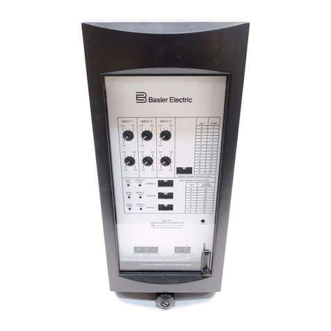
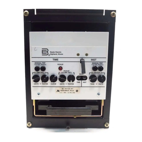
Basler BE1-24 User manual

INSTRUCTION MANUAL
for
BE1-24
VOLTS PER HERTZ
OVEREXCITATION RELAY
Publication: 9 1716 00 990
Revision: E 08/98

BE1-32R, -32 O/U INTRODUCTION i
WARNING
To avoid personal injury or equipment damage, only qualified personnel should
perform the procedures presented in this manual.
INTRODUCTION
This Instruction Manual provides information concerning the operation and installation of BE1-24 Volts per
Hertz Overexcitation Relay. To accomplish this, the following is provided.
Specifications
Functional characteristics
Installation
Operational Tests
Mounting Information

ii BE1- 24 Introduction
CONFIDENTIAL INFORMATION
OF BASLER ELECTRIC COMPANY, HIGHLAND, IL. IT IS LOANED FOR CONFIDENTIAL USE, SUBJECT TO
RETURN ON REQUEST, AND WITH THE MUTUAL UNDERSTANDING THAT IT WILL NOT BE USED IN ANY
MANNER DETRIMENTAL TO THE INTEREST OF BASLER ELECTRIC COMPANY.
First Printing: May 1988
Printed in USA
© 1995, 1998 Basler Electric Co., Highland, IL 62249
August 1998
It is not the intention of this manual to cover all details and variations in equipment, nor does
this manual provide data for every possible contingency regarding installation or operation.
The availability and design of all features and options are subject to modification without
notice. Should further information be required, contact Basler Electric Company, Highland,
Illinois.
BASLER ELECTRIC
ROUTE 143, BOX 269
HIGHLAND, IL 62249 USA
http://www.basler.com, info@basler.com
PHONE 618-654-2341 FAX 618-654-2351

BE1-24 Introduction iii
CONTENTS
SECTION 1 GENERAL INFORMATION.....................................................................................1-1
Purpose....................................................................................................................1-1
Overexcitation..........................................................................................................1-1
Volts Per Hertz Principle..........................................................................................1-1
Relay Characteristics...............................................................................................1-2
Applications..............................................................................................................1-2
Model And Style Number.........................................................................................1-6
Sample Style Number........................................................................................1-6
Specifications...........................................................................................................1-8
SECTION 2 HUMAN-MACHINE INTERFACE............................................................................2-1
Controls and Indicators............................................................................................2-1
SECTION 3 FUNCTIONAL DESCRIPTION................................................................................3-1
General....................................................................................................................3-1
Functional Description .............................................................................................3-1
Thumbwheel Switches ......................................................................................3-1
Input Sensing.....................................................................................................3-1
Third Harmonic Rejection Filter.........................................................................3-2
Microprocessor..................................................................................................3-2
Trip Level Detector............................................................................................3-2
Digital-to-Analog Converter...............................................................................3-2
Output Functions......................................................................................................3-3
Inverse Square Timing .....................................................................................3-3
Definite Time Alarm...........................................................................................3-4
Instantaneous Trip Output ................................................................................3-4
Outputs ....................................................................................................................3-4
Timing Status Display ..............................................................................................3-4
Watchdog Circuitry...................................................................................................3-5
Relay Fail Function..................................................................................................3-5
Targets.....................................................................................................................3-5
Built-In-Test..............................................................................................................3-5
Push-To-Energize-Output Pushbuttons...................................................................3-5
Power Supply...........................................................................................................3-5
SECTION 4 INSTALLATION.......................................................................................................4-1
General....................................................................................................................4-1
Relay Operating Precautions...................................................................................4-1
Dielectric Test..........................................................................................................4-1
Mounting..................................................................................................................4-1
Connections.............................................................................................................4-8
SECTION 5 OPERATIONAL TEST.............................................................................................5-1
General....................................................................................................................5-1
Relay Operating Precautions...................................................................................5-1
Built-In-Test..............................................................................................................5-1
Operational Test Procedures...................................................................................5-1
Pickup................................................................................................................5-2
Instantaneous Time Verification........................................................................5-3
Definite Time Delay Alarm.................................................................................5-3
Inverse Square Timing ......................................................................................5-4
iv BE1- 24 Introduction
CONTENTS - CONTINUED
SECTION 6 MAINTENANCE ......................................................................................................6-1
General ....................................................................................................................6-1
In-House Repair.......................................................................................................6-1
Storage ....................................................................................................................6-1
Test Plug..................................................................................................................6-1
SECTION 7 MANUAL CHANGE INFORMATION......................................................................7-1
Changes................................................................................................................... 7-1

1
(webers/meter2)
e
Nd
1
dt
1
1
N
P
edt
e
2Esin(
7
t)
1
2E
N
7
cos(
7
t)
1
max
2E
N
7
x
1
2
%
f
V
N
1
max
x
1
2
%
N
V(volts)
f(hertz)
BE1-24 General Information 1-1
SECTION 1 • GENERAL INFORMATION
PURPOSE
BE1-24 Volts Per Hertz Overexcitation Relays are specifically designed to protect transformers, generators
and iron core reactors from the adverse effects of excessive heating resulting from overexcitation.
Overexcitation exists whenever the per unit volts per hertz exceeds the equipment design limitations.
OVEREXCITATION
Overexcitation is excessive flux density in the magnetic core of the protected equipment. Once the magnetic
core is at or near saturation, any increase in the applied voltage will cause the excess flux to travel outside
the core through the air or the structural steel components. Structural steel components are not laminated,
and stray flux in these components cause large eddy current losses and hysteresis losses. This generates
excessive heat. Also, the excess flux through the air requires a large current in the winding which creates
excessive heat.
Overexcitation of transformers, iron core reactors, and generators can cause severe damage. This
overheating causes the deterioration of adjacent insulation, and if allowed to persist, will lead to equipment
failure. Modern designs are especially sensitive to overexcitation because they operate with high flux
densities. Overexcitation can result from an increase in voltage or a decrease in frequency.
VOLTS PER HERTZ PRINCIPLE
Protective relaying must determine the level of flux density from the secondaries of voltage and/or current
transformers. The following demonstrates the relationship between the actual flux density, voltage, and
frequency as monitored by the protective relays.
By Definition, Flux Density: (1)
Faraday’s Law: (2)
Therefore: (3)
Let: (4)
Then: (5)
And: (6)
Therefore: (7)

1-2 BE1-24 General Information
NOTE
Actual damage curves must be obtained from the equipment manufacturer for the
particular equipment to be protected.
where:
is the flux density (webers/meter )
2
0
is the flux (webers)
is the flux linkage (weber-turns)
7
is equal to 2
%
f
is the cross sectional area (meter )
2
is the number of turns
e is the instantaneous voltage
E is the RMS voltage
V is the applied voltage
f is the frequency in hertz
From (6) and (7), it may appear that the peak flux is directly proportional to the voltage. This may lead to the
conclusion that overvoltage protection is adequate. However, overvoltage relaying provides only limited
overexcitation protection at or near the rated the frequency. A significant reduction in frequency without a
reduction in voltage has an effect similar to overvoltage. This can be seen with an examination of (7). The
flux is directly proportional to the voltage and inversely proportional to the frequency. Thus, the overexcitation
of magnetic circuits is directly proportional to the ratio between the voltage and frequency (volts/hertz).
For example, a transformer with a 1.1 per unit voltage design rating will be overexcited if the voltage exceeds
110% at the rated frequency or the frequency drops below 90.9% at the rated voltage.
RELAY CHARACTERISTICS
BE1-24 relay emulate heating and cooling characteristics of the protected equipment. By accumulating time
towards tripping whenever the timed trip volts/hertz pickup setting is exceeded, the relays simulate heat build
up within the protected equipment. Once heated, metal does not cool instantaneously. To accommodate
this characteristic, the BE1-24 also has a linear reset characteristic which can be adjusted to follow the
cooling rate of the protected equipment. So, as heat builds up and dissipates within the protected equipment
due to overexcitation excursions, it is closely protected by the BE1-24 tripping and reset characteristics.
The definite time alarm feature allows even more effective use of the equipment by alerting operators that
a potentially dangerous condition exists. Once alerted, the operator can take corrective action to prevent the
necessity of a relay trip. Alternatively, the definite-time alarm output contact can be used to initiate automatic
corrective action.
The optional instantaneous trip provides high-speed tripping for the most severe conditions.
APPLICATIONS
Volts/hertz overexcitation relays primarily protect directly connected generator unit step-up transformers.
These transformers may besubjected to excessive volts/hertz during generator startup or shutdown, power
system islanding, or remote load rejection.
Typically, the generator field is applied when the machine is above 90% of rated speed. If the field is applied
early, or not removed soon enough, the terminal voltage may be much higher than appropriate for the actual
frequency. Many generator automatic voltage regulators and excitation systems are equipped with a
volts/hertz characteristic. BE1-24 relays protect associated step-up transformers from overexcitation caused
by failureof the field application/removal scheme, or by failure of the automatic voltage regulator during start-
up and shutdown.
An excessive load-to-generation ratio during power system islanding, or during local loss of generation, can
create an underfrequency condition which may result in the overexcitation of the generator unit step-up
transformer. The BE1-24 relay acts as backup protection for underfrequency relaying, and for volts/hertz

BE1-24 General Information 1-3
control functions which may be incorporated in the generator voltage regulator.
The sudden removal of load from a generator results in an increase in terminal voltage especially if a
transmission line remains connected as the only load. The automatic voltage regulator should act to bring
the voltage down to a safe level before equipment damage occurs. However, in the event of a regulator
failure, the BE1-24 protects equipment from damage.
Load tap changing (LTC) transformers and line voltage regulators may be subjected to excessive volts/hertz
during abnormal system frequency conditions. This is the inevitable consequence of their constant voltage
control function. Failure of the LTC controller may result in a runaway condition producing dangerously high
voltages. The BE1-24 provides close protection for such equipment while allowing a wide range of voltage
control operations.
Figure 1-1 illustrates the advantage of applying the inverse square timing characteristic rather than the two-
step protection scheme. This provides closer coordination and prevents unnecessary tripping of the
protected equipment.
In this example, two steps of definite time delay overexcitation protection are applied to provide protection
that approximates the transformer damage curve. One step is set for 110 percent and 60 seconds. The
second step is set for 118 percent and 6 seconds. However, by using the inverse square characteristic, the
damage curve can be even more closely approximated. The resulting protection is more closely coordinated
with adequate margin. Note that the cross hatched area reveals the overprotected area that results from
use of a two step scheme.
When a transformer and generator are to be protected by a single volts-per-hertz overexcitation relay, the
overexcitation curves for both pieces of equipment must be considered. Figure 1-2 illustrates a situation
where these two units have different characteristics and yet can both be protected by the BE1-24. Utilizing
the alarm function (with its definite time delay), and in combination with the inverse square characteristic, the
transformer generator combination may be protected with a single BE1-24 Volts-Per-Hertz Overexcitation
Relay. If necessary, the instantaneous element can be set to a percentage (105%) of the rated excitation
to provide an early warning alarm. This alarm can enable the operator controlling the excitation to recover
and prevent tripping.

1-4 BE1-24 General Information
Figure 1-1. Inverse Square vs. Two-Step

BE1-24 General Information 1-5
Figure 1-2. Protection Characteristics of the BE1-24

1-6 BE1-24 General Information
MODEL AND STYLE NUMBER
Electrical characteristics and operational features included in a specific relay are defined by a combination
of letters and numbers which constitute the relay style number. The model number, BE1-24, designates the
relay as a Basler Electric Class 100 Volts Per Hertz Overexcitation Relay. The style number together with
the model number describe the features and options in a particular relay and appear on the front panel,
drawout cradle, and inside the case assembly.
Sample Style Number
Figure 1-3 illustrates how a style number determines and describes the relay features. For example, if the
style number were A1H-F1J-D1S2F, the relay would have the following features.
A- Single-phase voltage sensing
1- Sensing input range of 1.00 to 3.99 V/Hz
H- Alarm output NC, trip output NO
F1 - Inverse square timing
J- 125 Vdc power supply
D- All targets current operated
1- Instantaneous trip function included
S- Push-to-energize-output pushbuttons
2- Normally open auxiliary output contact
F- Semi-flush mounting

BE1-24 General Information 1-7
Figure 1-3. Style Number Identification Chart

1-8 BE1-24 General Information
SPECIFICATIONS
Voltage Sensing The sensing input transformer has a voltage measuring range of 10
to 360 Vac with a typical frequency measuring range of 3 to 72
hertz. Maximum sensing burden is 3.5 VA. The sensing circuits
have an absolute maximum rating of 5 volts/hertz to enable the
relay to perform correctly for all system operating conditions.
Power Supply Power for the internal circuitry may be derived from ac or dc
external power sources. Power supply voltages, ranges, and
burden are provided in Table 1-1.
Table 1-1. Power Supply Types And Specifications
Type Nominal Input Input Voltage Burden at
Voltage Range Nominal
K (Mid Range) 48 Vdc 24 to 150 Vdc 4.0 W
J (Mid Range) 125 Vdc 24 to 150 Vdc 4.0 W
120 Vac 90 to 132 Vac 10.0 VA
L (Low Range) 24 Vdc 12 † to 32 Vdc 4.0 W
Y (Mid Range) 48 Vdc 24 to 150 Vdc 4.0 W
125 Vdc 24 to 150 Vdc 4.0 W
Z (High Range) 250 Vdc 62 to 280 Vdc 5.0 W
240 Vac 90 to 270 Vac 12.0 VA
† Type L power supply initially requires 14 Vdc to begin operating. Once operating, the
voltage may be reduced to 12 Vdc and operation will continue.
Outputs Output contacts are rated as follows:
Resistive
120/240 Vac Make 30 amperes for 0.2 seconds, carry 7 amperes continuously,
and break 7 amperes.
125/250 Vdc Make 30 amperes for 0.2 seconds, carry 7 amperes continuously,
and break 0.3 amperes.
Inductive
120/240 Vac, Make 30 amperes for 0.2 seconds, carry 7 amperes
125/250 Vdc continuously, and break 0.3 ampere. (L/R = 0.04).
Pickup Adjustment Ranges Adjustable from 1.00 to 3.99 in 0.01 V/Hz increments. (Any
(Timed Trip, Alarm, and optional setting above 3.99 V/Hz or below 1.00 V/Hz is limited to 3.99 and
Instantaneous Trip) 1.00 V/Hz respectively.)
Pickup Accuracy Pickup accuracy is dependent upon sensed frequency as shown in
Table 1-2.

BE1-24 General Information 1-9
Table 1-2. Pickup Accuracy and Frequency
Sensed Frequency Accuracy at 25
(
(
C Temperature Stability from a
Ref. Measurement at 25
(
(
C
40-72 hertz ± 1.0 hertz ± 1.5%
20-40 hertz ± 2.0 hertz ± 3.0%
3-20 hertz ± 8.0 hertz ± 12.0%
Timing Ranges
Inverse Square
(Timed Trip) Adjustable from 0.1 to 10 in 0.1 increments to select the individual
characteristic curve which best matches the protected equipment's
damage curve. Minimum time delay is 0.25 seconds and maximum
time delay 1000 seconds. A setting of 0.0 is equivalent to a setting
of 10.0. See Figure 1-4 or Figure 1-5 for characteristic curves.
Reset Time (Available for the Timed Trip function only.) Adjustable in seconds
per percent of full scale trip time from 0.1 to 9.9 in 0.1 second
increments. Note that this means entering a reset rate rather than
a reset time.
A setting of 0.0 enables instantaneous reset time.
Definite Time Adjustable from 0.1 to 9.9 seconds in 0.1 second increments. A
(Alarm) setting of 0.0 enables the Alarm output to be instantaneous.
Instantaneous Trip 132 milliseconds at 60 Hz.
(Optional)
Timing Accuracies Inverse square and definite time accuracies are as follows:
Inverse Square
(Timed Trip) Follows the curve shown in Figure 1-4 to an accuracy given in the
table below for any combination of TIME DIAL and TIME TRIP
PICKUP settings: repeatable within ±5%.
V/Hz M Accuracy
V/Hz > 1.50 M > 1.1 ±10%
V/Hz < 1.50 1.1 < M < 1.2 ±15%
V/Hz < 1.50 M > 1.2 ±10%
Where M = multiples of pickup setting.
Definite Time Accurate to within ± one-half of the least-significant-digit time plus
(Alarm) 25 milliseconds or 1.0% (whichever is greater).
Targets Magnetically latching, manually reset target indicators are optionally
available to indicate that a trip output contact has closed. Either
internally operated or current operated targets may be selected.
Current operated targets require a minimum of 0.2 A in the output
trip circuit to actuate, and trip current must not exceed 30 A for 1
second, 7 A for 2 minutes, and 3 A continuous. Current operated
targets only if the relay has normally open (NO) output contacts.

1-10 BE1-24 General Information
Push-To-Energize-Output Accessible with a thin non-conducting rod through the front panel,
Pushbuttons push-to-energize pushbuttons are available to energize each output
relay for testing the external control/protective system wiring.
Shock In standard tests, the relay has withstood 15 g in each of three
mutually perpendicular axes without structural damage or
degradation of performance.
Vibration In standard tests, the relay has withstood 2 g in each of three
mutually perpendicular axes swept over the range of 10 to 500
hertz for a total of six sweeps, 15 minutes each sweep, without
structural damage or degradation of performance.
Isolation In accordance with IEC 255-5 and ANSI/IEEE C37.90, one minute
dielectric (high potential) tests as follows:
All circuits to ground: 2121 Vdc
Input to output circuits: 1500 Vac or 2121 Vdc
Surge Withstand Capability Qualified to ANSI/IEEE C37.90.1-1989,
Standard Surge Withstand
Capability (SWC) Tests for Protective Relays and Relay System,
and IEC 255-5,
Impulse Test and Dielectric Test
.
Impulse Test Qualified to IEC 255-5.
Radio Frequency Maintains proper operation when tested in accordance with IEEE
Interference (RFI) C37.90.2-1987
Trial-Use Standard Withstand Capability of Relay
Systems to Radiated Electromagnetic Interference from
Transceivers.
UL Recognition UL Recognition per Standard 508, UL File No. E97033. Note:
Output contacts are not UL Recognized for voltages greater than
250 volts.
Temperature
Operating
-40
(
C (-40
(
F) to +70
(
C (+158
(
F)
Storage
-65
(
C (-85
(
F) to +100
(
C (+212
(
F)
Weight 17.3 pounds maximum
Case Size All relays are supplied in a M1 double-ended case.

BE1-24 General Information 1-11
Figure 1-4. Inverse Square Characteristic Curves

1-12 BE1-24 General Information
Figure 1-5. Inverse Square Characteristic Curves (Multiples of Pickup vs. Time)

BE1-24 Human-Machine Interface 2-1
SECTION 2 • HUMAN-MACHINE INTERFACE
CONTROLS AND INDICATORS
Table 2-1 lists and briefly describes the BE1-24 controls and indicators. Reference the callouts to Figure
2-1. Table 2-1. BE1-24 Controls and Indicators
Locator Control or Indicator Function
A INST. PICKUP
(Optional) Thumbwheel adjustment establishes the pickup point for the
instantaneous output. Adjustable from 1.0 to 3.99 V/Hz in 0.01
V/Hz increments.
B TIME TRIP PICKUP Thumbwheel adjustment establishes the pickup point for the
time trip output. Adjustable from 1.0 to 3.99 V/Hz in 0.01 V/Hz
increments.
C TIME DIAL Thumbwheel adjustment to select individual inverse square
characteristic curve. Adjustable from 0.1 to 10.0 in 0.1
increments. To select 10.0, set 0.0 (there is no tens digit
thumbwheel) on the TIME DIAL thumbwheels.
D RESET Thumbwheel adjustment establishes the linear rate of reset per
percent of full-scale trip time to model the protected
equipment's cooling rate. Adjustable from 0.1 to 9.9 seconds
in 0.1 second increments. A setting of 0.0 enables the reset
time to be instantaneous.
E ALARM PICKUP Thumbwheel adjustment establishes the pickup point for the
alarm output. Adjustable from 1.0 to 3.99 V/Hz in 0.01 V/Hz
increments.
F ALARM TIME DELAY Thumbwheel adjustment establishes the definite time delay for
the alarm output. Adjustable from 0.1 to 9.9 seconds in 0.1
second increments. A setting of 0.0 enables the alarm output
to be instantaneous.
G ALARM PICKUP
Indicator When ON, red LED indicates that the alarm pickup setting has
been exceeded and that the unit is timing.
H POWER Indicator When ON, red LED indicates that the power supply is providing
nominal ±12 Vdc to internal operating circuitry.
ITarget Reset Lever Mechanical lever used to reset magnetically latched target
indicators.
JTrip Target Indicators Magnetically latched, manually reset target indicators provide
visual indication that the respective trip output relay has been
energized. Must be manually reset.
K PUSH-TO-ENERGIZE
OUTPUT Pushbuttons provide manual actuation of the output contacts
by insertion of a 1/8 inch thick non-conducting rod (not
supplied) through the access holes in the front panel.
LTiming Status Display
(TSD) A series of 10 LED's used to indicate the accumulation of time
towards trip or reset. Each LED represents approximately 10%
of the total time accumulated. See Section 3 for complete
functional description.
M TIME TRIP PICKUP
Indicator When ON, red LED indicates that the time trip pickup setting
has been exceeded and that the unit is timing.

2-2 BE1-24 Human-Machine Interface
Figure 2-1. Location of Controls and Indicators

BE1-24 Functional Description 3-1
SECTION 3 • FUNCTIONAL DESCRIPTION
GENERAL
BE1-24 Volts Per Hertz Overexcitation Relays are microprocessor based to match application requirements,
achieve accuracy of measurements and repeatability.
FUNCTIONAL DESCRIPTION
The following descriptions are referenced to the functional block diagram, Figure 3-1.
Figure 3-1. Functional Block Diagram
Thumbwheel Switches
Thumbwheel switches on the front panel of the relay are easily adjusted to define the relay operating
characteristics. These thumbwheel settings define the volts per hertz pickup levels for the time delayed trip,
the alarm, and the (optional) instantaneous trip functions. Thumbwheel settings also define the time delay
for tripping and reset.
Input Sensing
BE1-24 relays have input sensing transformers that sense a single phase of system voltage. These
transformers have a measuring range of 10 to 360 volts at frequencies from 3 to 72 hertz. The rating of five
volts per hertz identifies the absolute maximum voltage at a given frequency at which the relay is able to
perform correctly for all system operating conditions.
Table of contents
Other Basler Relay manuals

Basler
Basler BE1-79A User manual

Basler
Basler BE1-50/51B-219 User manual

Basler
Basler BE1-25/79TR User manual

Basler
Basler BE1-50/51B-214 User manual

Basler
Basler BE1-CDS220 User manual

Basler
Basler BE1-40Q User manual

Basler
Basler BE1-51B User manual

Basler
Basler BE1-51M User manual

Basler
Basler BE1-67N User manual

Basler
Basler BE1-DFPR User manual

Basler
Basler BE1-50M User manual

Basler
Basler BE1-59N User manual

Basler
Basler BE1-59N User manual

Basler
Basler Class 300 User manual

Basler
Basler BE1-50/51M-222 User manual

Basler
Basler BE1-32R User manual

Basler
Basler BE1-32 User manual

Basler
Basler BE1-27 User manual

Basler
Basler BE1-79 User manual

Basler
Basler BE1-50BF User manual