BassBoss MK3 Series User manual
Single 12”
Powered Monitor
CCM12-MK3
User ManUal

CCM12-MK3 User Manual bassboss.com
3
2
Table of Contents
Overview 2
QuickStartGuide 4
OutboardProcessorWarning 5
SetupProcedure 5
OperationandControls 6
IndicatorLEDs 6
HowtoUsethePresets 7
Pre-InstalledOnboardPresets 8
PowerDistribution 9
Troubleshooting 9
Specifications 10
Warranty 11
SafetyInformation 12
ImportantNotes 13
FCCComplianceNotice 13
Overview
The CCM12-MK3 is a Compact Coaxial Monitor with a host of features intended for professional
performers which also functions as an excellent main or fill monitor for venues with limited space.
C = Compact - Small footprint, small frontal area, lightweight. The front of the cabinet is 50% smaller
than most 12” monitors that have a separate tweeter horn. This takes up less space on stage, and
anywhere else you might want the power of a 12” 2-way monitor. The driver features a Neodymium motor
and the class D amplifier has a lightweight, switch-mode power supply. The cabinet is Birch plywood,
which is heavier than plastic, but the strength of the wood allows the cabinet to be made smaller, and
sound better.
C = Co-Axial - Absolutely consistent coverage pattern, highly resistant to feedback. This co-axial driver
delivers an 80-degree conical coverage pattern that is consistent o-axis. The advantage to this is
two-fold. First, the consistency allows the performer or listener the freedom to move around within the
Single 12”
Powered Monitor
CCM12-MK3
Estemanualestádisponibleenespañolennuestrositiowebenbassboss.com/support

CCM12-MK3 User Manual bassboss.com
3
pattern without the character of the sound changing. Conventional 2-way monitors have the tweeter
above, to the side or below the woofer. This results in a dierent frequency response as you move left
to right or forward and back. It’s much more diicult to prevent conventional monitors from feeding
back because the response peaks change in frequency as you move through their inconsistent patterns,
leaving you chasing feedback every time a mic moves. A Co-axial is far more consistent no matter where
you move, which is better for performers and audiences alike. Aside from delivering a more consistent
and intelligible sound field, perhaps the biggest advantage of the consistency of the symmetrical pattern
co-axial monitor is its relative immunity to feedback.
M = Monitor - 3 dierent upward angles plus straight ahead - and - fly-points and brackets for ceiling
and wall mounting. It has 3 dierent upward angles. The first angle is set up for standing performers who
like their monitors at their feet. We’re thinking about vocalists, with or without instruments, who need
clear monitors when they step up to the mic and appreciate being able to step back out of the monitor
coverage when they want to. The second angle is for seated performers that need the monitor to be
aimed a little lower. Whether playing keyboards, drums or slide-guitar, the monitor should be pointed at
your head, not over your head. This lower angle can also be used to cover a larger area farther from the
monitors, such as for a choir, background vocalists or a horn section. The third angle is for placement
on a subwoofer or a table. Here we’re thinking about drummers who would want the monitor on a sub,
of course, or anyone who works with electronics on a table, and wants near-field monitors they can put
on their work surface and actually aim them in the right direction. There’s one more placement angle for
the CCM to be used as a monitor and that’s straight ahead. The CCM has a pole socket that allows it to
be used on a stick above a sub, or on a tripod, for DJ monitors or stage side-fills. While it’s not strictly a
“monitor” position, the CCM can also be used as a front-fill on the stage edge or on that center-cluster
subwoofer array. And when you need a monitor mounted to the wall or to the ceiling, the CCM has M10
fly-points. The internally reinforced fly-points can also be used to attach the CCM to a wall or ceiling
mounted bracket.
12 = 12” woofer, this one with a 3” voice coil, delivers the low frequencies. A 3” coil, 1.4” throat compression
driver firing through the center delivers the highs. The cone of the woofer serves as an extension of the
machined aluminum conical horn that comprises the woofer’s pole piece, making it possible to generate
very high output from a very small total surface area. Both share a common Neodymium motor structure
and a cast aluminum basket. The woofer is housed in a sealed Birch enclosure to provide extendable
frequency response, consistent phase response and tight transient response.
MK3 = Completely integrated processing. Eight on-board presets allow for a variety of configurations
at the touch of a button. The on-board presets provide a variety of settings that are optimized for floor-
monitor duty, including settings that account for the boundary loading at each wedge angle as well as
settings to extend LF output with limited SPL and to maximize SPL when used with a subwoofer. The
proprietary BASSBOSS processing ensures exceptional sound quality thanks to its premium quality,
high-fidelity electronics. Its ultra-low noise CODECS, 96kHz sampling rate processor and high-resolution
amplification are some of the finest in the industry.
Powered Loudspeaker = The amplifier in the CCM features a Class D SMPS with PFC, providing two
channels, 900W LF and 300W HF. Yes, this is a bi-amped wedge. The sealed enclosure provides the
flexibility to choose between low-frequency extension or high-SPL operation from the same compact
loudspeaker. BASSBOSS loudspeakers are protected for safe, high-power operation. Optimized signal
processing, premium quality drivers, power-matched amplification and comprehensive protections
ensure that no matter the demand, they keep their cool, keep their character and keep on working.

CCM12-MK3 User Manual bassboss.com
5
4
Quick Start Guide
1. Ensure the cabinet is secure and stable.
2. Connect signal via the XLR-F input.
3. Connect the XLR-M connector to additional subs or tops.
4. Connect the mains power and verify the “Ready” LED is lit.
BASSBOSS systems are easy to set up quickly. The best possible results are achieved consistently
because of the integrated nature of the designs. All BASSBOSS loudspeakers are complete, integrated
systems, featuring the cabinet, transducer, amplifier and a comprehensive suite of processing. Setup
is particularly easy because the products integrate with each other.
Provided the cabinets are physically aligned, any BASSBOSS sub can be combined with any
BASSBOSS top and their outputs will be phase-coherent. This means no cancellations and no gaps in
the response at the crossover frequency, regardless of which preset is selected.
The on-board BASSBOSS processing allows for the following:
Any BASSBOSS powered subwoofer can be combined with any other BASSBOSS Powered subwoofer
and their outputs will sum coherently. (i.e.: in phase with each other.)
Any BASSBOSS powered subwoofer or combination of BASSBOSS powered subwoofers can be
combined with any BASSBOSS powered top and their outputs will sum coherently through the
crossover region.
HOWEVER only one model of top should be used at a time. An assortment of dierent tops cannot be
stacked together and still achieve coherence and clarity.
The following tops should be used individually, i.e. should NOT be arrayed:
AT312 (Co-axial point-source Main)
DiaMon (Co-axial point-source satellite)
SV9 (2-way monitor with Satellite mode)
The following tops can be used in arrays:
MFLA (Medium Format Line Array, up to 20 cabinets can be arrayed)
AT212 (Horizontally arrayable when necessary)
DV12 (Arrayable in PAIRS ONLY with the upper box of the pair inverted.)

CCM12-MK3 User Manual bassboss.com
5
Outboard Processing Warning
Third-party outboard processing (Drive Racks, etc.) are not recommended and are not necessary
with BASSBOSS MK3 series powered loudspeakers. Outboard processing will not improve, and
will very likely degrade the sound quality, reliability and output capacity. Using external processing
inappropriately can cause driver damage that is not covered by warranty.
The internal processing can accomplish everything an external processor could accomplish without
degrading the sound quality and without putting components at risk. Before considering using an
outboard processor, contact BASSBOSS customer service with your use-case scenario for assistance
in setting up the internal processing to achieve your goals.
Setup Procedure
Once the the cabinet is in the desired location, signal cables should be connected via the XLR-F input.
It’s recommended to run balanced signal cables to minimize the chance of noise and ground-loop hum.
The incoming signal should be unprocessed because all the necessary processing is done in the built-
in DSP. The signal should be run directly from the outputs of a mixer or controller.
The XLR-M connector provides a full-range, unprocessed, pass-through connection to additional
cabinets. This output can be connected to additional subs or tops. Up to 12 cabinets can be connected
on a single output from a mixer or controller.
Connecting the mains power. The power connector is a Neutrik powerCON True1 TOP waterproof type.
The power connector inserts with the silver tab rotated counter clockwise from vertical, at about the
10:00 position, and once inserted, rotates clockwise to the 12:00 position to lock in place. Once locked,
this connector is waterproof.
This connector also serves as the power switch. To disconnect and remove the connector, pull back
on the silver tab to unlock it and rotate it counter clockwise. Once rotated to the insertion angle, the
connector can be removed.
When connecting and disconnecting, no force should need to be applied. If the connector doesn’t
insert and rotate smoothly, either it’s in the wrong position or it’s damaged and should be replaced.
Always use a grounded outlet. The supplied power cord includes a standard grounding NEMA 5-15
(Edison) 120-Volt US wall plug. In unfamiliar locations it’s recommended to verify the correct wiring of
outlets before powering your system.
It’s highly recommended to connect all signal and power cords to the speakers before plugging the
power cords into mains outlets. When your speaker is powered on, you’ll see all the indicator lights turn
on and then show the system’s current status.
Although the DV12 cabinet is equipped with a 35mm steel pole socket, DO NOT use this speaker on a
tripod or extension pole. This socket is to be used with a special, short section of pole to prevent it from
moving once stacked on a subwoofer.

CCM12-MK3 User Manual bassboss.com
7
6
Operation & Controls
There are 2 controls on the amplifier.
1: Input
This knob adjusts the input level from -72dB to -0dB. To avoid distortion and clipping, make sure the
input signal doesn’t exceed +22dB and the incoming signal doesn’t reach clipping before you achieve
the desired sound level.
While the amplifier has built-in limiters and safety features to protect itself and the speaker, it can’t
protect the speaker from distorted incoming signals. The amplifier will simply amplify the clipped signal,
which can do the same damage as clipping an amplifier. Since it’s essentially impossible for these
amplifiers to clip, signal-level clipping is the most common cause of damage to these speakers.
If you hear distortion, lower the input level right away.
2: Preset Select
Pressing the Preset Select button cycles through presets 1-8, and pressing it again after preset 8 returns
to preset 1. Each preset includes all necessary low-pass and high-pass filters at the selected frequencies
and all the necessary alignments to maintain phase coherence in the crossover range when used with
other BASSBOSS powered speakers.
Presets help you fine-tune the balance between the subwoofers and top speakers. More details on the
dierent combinations are on page 7.
Indicator LEDs
Indicator LEDs – Left side, bottom to top:
Ready: Indicates that power is on and the system is ready to play.
Signal: Indicates the presence of input signal.
-12dB: Indicates there is 12dB of headroom remaining before reaching maximum output.
-6dB: Indicates there is 6dB of headroom remaining before reaching maximum output.
Limiting: Indicates one of the channels is reducing the incoming signal level to prevent overdrive.
Overheat: Indicates the amplifier is reducing output to prevent shut-down from overheating.
Protect: Indicates the amplifier is shut down due to a condition that could cause further damage.
The Protect LED also is engaged when the system has been muted via the software.
Comm Link: Indicates communication is active on the LAN connection(s).
Indicator LEDs, Right Side, Bottom to top:
Presets 1-8 - The illuminated LED indicates the corresponding preset is loaded.
CCM12-MK3 User Manual bassboss.com
7
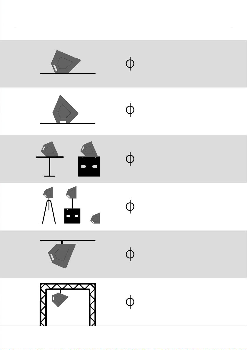
How to Use the Presets
Ground / Floor
Position 1 -
Ideal for Standing Performers, use :
• Preset 1 (Full-Range)
• Preset 4 (High-passed)
1.
Ground / Floor
Position 2 -
Ideal for Seated Performers, use :
• Preset 3 (Full-Range)
• Preset 4 (High-passed)
2.
Position 3 -
Ideal for Tabletop Placement
or for placement on a Subwoofer
as a Drum Monitor, use :
• Preset 5 (Full-Range)
• Preset 6 (High-passed)
3. Tabletop On Sub
or
Ceiling
Mounted Ceiling Mounting -
For Ceiling Mounting, use :
• Preset 5 (Full-Range)
• Preset 6 (High-passed)
5.
Flown or Truss Mounted -
For Flown or Truss Mounted, use :
• Preset 7 (Full-Range)
• Preset 8 (High-passed)
6.
Position 4 -
For Tripod Placement,
For Pole Mounting above a sub, or
For Front Fill, use :
• Preset 7 (Full-Range)
• Preset 8 (High-passed)
4. Tripod
Mount
Pole Mount
above Sub
or
or
Front Floor Fill
Flown
or Truss
Mounted

CCM12-MK3 User Manual bassboss.com
9
8
Pre-Installed Onboard Presets
All presets include phase compensation for integration with BASSBOSS subwoofers.
Preset 1: Standing Performer*
Preset 2: Standing Performer, max SPL
Preset 3: Seated Performer*
Preset 4: Seated Performer, max SPL
Preset 5: Tabletop full-range*
Preset 6: Tabletop Max SPL (use on or with sub(s)
Preset 7: Straght Forward Full Range*
Preset 8: Straight Forward Max SPL (use with sub(s)
All Max SPL presets are compatible with all BASSBOSS subwoofers
Additional presets are accessible through software.
See “How to Use the Presets” section for more information.
New presets will be available for download at bassboss.com/software as they are developed.
To be notified when new presets are released register your gear at: www.bassboss.com/support
Instructions on linking to your computer for remote monitoring and control:
www.bassboss.com/software
Information and setup tips about how to get the best and most out of your system:
bassboss.com/edu
*(Greater demands for lower frequencies require greater restrictions on maximum output to prevent driver damage.)

CCM12-MK3 User Manual bassboss.com
9
Power Distribution
Connect no more than one 5000W or two 2500W subwoofer amplifiers to a single 20A circuit. If you
need to share circuits don’t exceed two BASSBOSS single-driver subwoofers or one double-driver
subwoofer along with one or two top speakers on the same circuit.
Although amplifiers for tops and subs may be specified to have the same power capacity, amplifiers
used for tops applications tend to draw significantly less current. Subwoofers draw far more current than
tops due to the demands for level and the duration of the notes.
The amplifiers can operate on mains supply from 100 to 250VAC. To connect to voltages other than
120V, a dierent mains connector plug must be used. Contact your salesperson for information about
purchasing cables for alternate voltages.
Pass-through Power connections can be used to power additional cabinets. With optional True 1 TOP
cables, power can be linked between subs and tops. Do not connect equipment that will draw more than
15A on a single power outlet. Contact your salesperson for information about linking power cables.
Avoid powering all subwoofers on the same circuit. Instead, use separate circuits for each subwoofer
and top speaker combo to help prevent overloading a single circuit and tripping a breaker.
Troubleshooting
If, after following the previous instructions for setup, you have no output from the loudspeaker:
Verify that the green Ready LED is lit. If NOT lit, check the following:
1. Is the power cord plugged into a live outlet?
2. Is the Neutrik powerCON connector rotated into the locked position?
If the green Ready LED is lit, check the following:
1. Is the red Protect LED illuminated? The unit may be in protect mode or set into mute via software.
2. Is the signal cable connected to the input?
3. Is the signal cable connected to an operating output at the other end?
4. Is there signal flowing to the input? Check the integrity of the cable against a dierent cable.
5. Is the volume knob turned all the way down or at a very low level?
6. Is the signal flowing to the input full-range?
Filters in the signal may remove the operating frequencies of the loudspeaker receiving them.
7. If you’re connected via LAN, check the level and filter settings in the software.

CCM12-MK3 User Manual bassboss.com
11
10
Specifications
Acoustical
LoudspeakerDescription: 2-wayactivemonitor.Self-poweredandinternallyprocessedwithpresets
forfull-rangeandmid-highoperation
FrequencyResponse(±3dB): 50Hz-19kHz(FullRange-Preset1)
MaximumSustainedOutput: 123dBSPL,1m,2pi,half-space
MaxSPL(Peak): 126dB
NominalDispersion(H°xV°): 80x80(Conical)
Electrical
Amplification: ClassD,1200W,2Channels
Processing: IntegratedcomprehensiveDSPprovidesallnecessaryhigh-passandlow
passfilters,equalization,phasealignmentandlimiting
ElectricalConnectors,Amp: NeutrikpowerCONTrue1TOPinputandpass-through
ElectricalConnector,Mains: NEMA5-15(Edison)standard3-pingroundedplug
VoltageOperatingRange:
100-240VAC,50-60Hz(Auto-sensing,autoswitchinguniversalsupply)
CurrentDraw,Nominal: 1.4A@120V-0.7A@240V(average,withmusic)
SignalInputConnector: XLR-F
SignalOutputConnector: XLR-M(pass-throughonly)
LANConnectors: EtherCONRJ45(x2)with2-portEthernetswitch
Physical
EnclosureType: Birchwoodenclosure-Sealeddirectradiatinglow-frequencysectionand
co-axiallyhorn-loadedhigh-frequencysection
Transducer(LowFrequency): 1x12in.diameter(300mm)neodymiummotorwooferwith3in.(76mm)
coppervoicecoil
Transducer(HighFrequency): 3in.(76mm)diaphragmcompressiondriveron1.4in.throat80-degreeconical
horn
CabinetConstruction: 18mmand15mmBirchplywood.Dadojoinery.Equippedwitha35mmsteel
polesocket
Dimensions(HxWxD): 14in.(35.5cm)x14in.(35.5cm)x11in.(28cm)
NetWeight: 29.76lbs(13.5kg)
ShippingWeight: 35lbs(15.9kg)
ExteriorFinish: Blackweatherproofbondedhigh-pressurepolyurea
Grill: Perforated,powder-coatedSteel
PoleSocket: 35mm,Steel
Optional
Cover: Heavy-duty padded nylon transport cover and carrying bag
Online Information: bassboss.com/ccm
Our proactive philosophy causes specifications to be subject to change whenever improvements are made.

CCM12-MK3 User Manual bassboss.com
11
Warranty
WARRANTY INFORMATION | Our fully-transferable warranty covers all BASSBOSS products.
STANDARD CABINET WARRANTY
BASSBOSS loudspeaker cabinet integrity, including all joinery, fasteners, handles and wood, is warranted against
defects in materials and workmanship for a period of six (6) years from the date of purchase. This warranty does not
cover items that are intended to wear and can be replaced if worn or damaged. Examples of items not covered by
this warranty are cabinet feet, grilles and the finish or coating applied to the cabinet.
ENHANCED COMPONENT WARRANTY
BASSBOSS amplifiers and electronic components are covered against failures due to defects in materials and/or
workmanship for a period of three (3) years from the date of purchase.
TRANSDUCER WARRANTY
Transducers are covered against failures due to defects in materials and/or workmanship for two (2) years from the
date of purchase.
OUR SUPPORT
Warranty support is a service, and part of that service includes helping you prevent failures and minimize repair and
shipping costs.
Please do not ship products without obtaining a return authorization number (RMA) by contacting BASSBOSS
at bassboss.com/support. If you need to ship your speaker for service, BASSBOSS technicians will provide
assistance on shipping and packaging requirements specific to your service needs.
WARRANTY LIMITATIONS
During the warranty period, if your loudspeaker malfunctions or fails due to any defect in components or
manufacturing, the failed parts will be repaired or replaced. This warranty does not extend to damage resulting
from improper installation, misuse, neglect or abuse. Warranty coverage and eligibility will be determined upon
inspection by BASSBOSS personnel. This warranty does not cover labor other than that authorized and performed
by BASSBOSS personnel. Service will be performed upon the return of the failed unit, together with its original
sales receipt or other proof of purchase, to BASSBOSS or an Authorized Service Facility. Purchaser is responsible
for all costs of shipping and handling. Cosmetic damage is specifically excluded from this warranty. This warranty is
rendered void if service, repairs and/or modifications are attempted or made by anyone not specifically authorized
by BASSBOSS to perform said services. Please contact BASSBOSS or your local BASSBOSS dealer before
attempting any repairs and before shipping parts in for service. This warranty gives you specific legal rights, and
you may also have other rights, which vary from state to state.

CCM12-MK3 User Manual bassboss.com
13
12
Safety Information
Important information regarding safety and the use of your loudspeakers:
To prevent potentially dangerous exposure to high levels of acoustic pressure, never stand in the
immediate vicinity of loudspeakers driven at a high level without hearing protection. Professional
loudspeaker systems are capable of causing sound pressure levels detrimental to human health.
When a transducer capable of producing high sound levels is being used, it is necessary to wear
ear plugs or protective earphones to prevent hearing damage.
Even seemingly non-critical sound levels (from approximately 95 dB SPL) can cause hearing
damage if people are exposed to it over a long period. Anyone exposed to these levels should use
appropriate hearing protection devices. System and venue owners and operators are encouraged
to make hearing protection devices available to all customers and sta members.
In order to prevent accidents when setting up the loudspeakers or loudspeaker stands, make sure
they are standing on a firm surface. Ensure that all additional hardware, fixings and fasteners used for
installation or mobile deployment are of an appropriate size and load safety factor.
Always use the included, factory installed, internally secured M10 fly points when supporting the
cabinets. Use appropriately load-rated hardware. Never hang loudspeakers from handles. Never drill or
screw into cabinets to attach lifting points.
Pay attention to the manufacturers’ instructions and to the relevant safety guidelines. Regularly check
the loudspeaker housings and accessories for visible signs of wear and tear, and replace them when
necessary. Regularly check all load bearing bolts in the mounting devices.
Caution: Loudspeakers produce a static magnetic field even if they are not connected or are not
in use. Therefore make sure when erecting and transporting loudspeakers that they are nowhere
near equipment and objects which may be impaired or damaged by an external magnetic field.
A distance of 3 feet (1m) should be maintained between loudspeakers and sensitive equipment such as
CRT monitors or magnetic storage media.
Never attempt to carry out any operations, modifications or repairs that are not expressly described in
this manual. Contact your dealer or BASSBOSS support if the product is not functioning properly.
For installation purposes BASSBOSS strongly recommends that this product be installed by a qualified,
professional installer who can ensure correct installation and certify that it is installed in compliance
with the regulations in force.
The audio system must comply with current local standards and regulations regarding electrical systems.

CCM12-MK3 User Manual bassboss.com
13
WARNING
This is a class A product. In a domestic environment, this product may cause radio
interferences, in which case the user may be required to take corrective measures.
FCC Compliance Notice
Note: This equipment has been tested and found to comply with the limits for a Class A digital device,
pursuant to part 15 of the FCC Rules. These limits are designed to provide reasonable protection against
harmful interference when the equipment is operated in a commercial environment.
This equipment generates, uses and can radiate radio frequency energy and, if not installed and used
in accordance with the instruction manual, may cause harmful interference to radio communications.
Operation of this equipment in a residential area is likely to cause harmful interference in which case the
user will be required to correct the interference at their own expense.
Important Notes
Shielded data cables must be used.
To minimize the occurrence of noise and interference, always use shielded signal cables. Avoid routing
signal or data cables close to equipment that produces high-intensity electromagnetic fields such as
transformers, power cables and loudspeaker wires.
Do not coil excess power cable. Do not coil or wrap power cables and signal or data cables together.
Manufacturer
True Lee Loudspeakers | BASSBOSS 2028 E Ben White Blvd. #240-8220 Austin TX 78741
We declare, under our sole responsibility, that to the best of our knowledge to which this
declaration relates, our products are in conformity with the applicable requirements.
Product: CCM12-MK3 Loudspeaker Intended use: Professional Audio Loudspeaker
bassboss.com/support
Need more assistance?
We’re here to help.
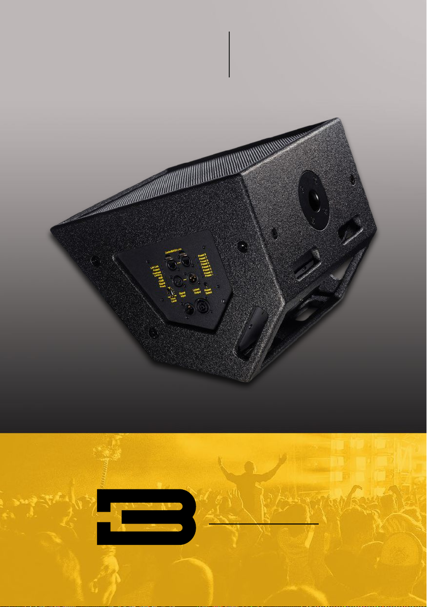
Single 12”
Powered Monitor
CCM12-MK3
This manual suits for next models
1
Table of contents
Other BassBoss Speakers manuals

BassBoss
BassBoss AT312 Attuned Top User manual

BassBoss
BassBoss SV8 Powered MicroMain User manual

BassBoss
BassBoss DiaMon 112 User manual

BassBoss
BassBoss AT312-MK3 User manual

BassBoss
BassBoss AT212-MK3 User manual

BassBoss
BassBoss AT312 Attuned Top User manual

BassBoss
BassBoss DV12-MK3 User manual

BassBoss
BassBoss DV12-MKII User manual

BassBoss
BassBoss DIAMON-MK3 User manual

BassBoss
BassBoss DV8 User manual


 manual")


