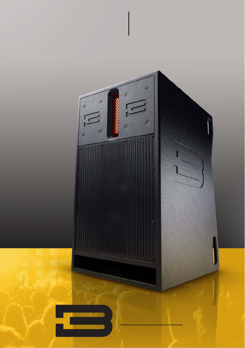
BassBoss DV12-MK3 User manual
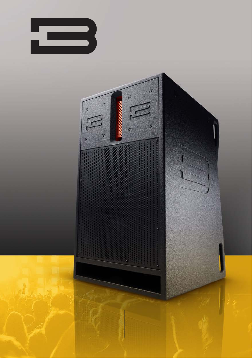
12” Powered
Loudspeaker
DV12-MK3
User Manual

DV12-MK3 User Manual bassboss.com
3
2
Table of Contents
Overview 2
QuickStartGuide 4
OutboardProcessorWarning 5
SetupProcedure 5
OperationandControls 6
IndicatorLEDs 6
HowtoUsethePresets 7
Pre-InstalledOnboardPresets 8
PowerDistribution 9
Troubleshooting 9
Specifications 10
Warranty 11
SafetyInformation 12
ImportantNotes 13
FCCComplianceNotice 13
controlled fans to ensure consistent operation under even the most extreme conditions.
The DV12-MK3 is the ultimate in plug and play, with universal voltage compatibility and no need for any outboard gear
other than a sound source. The processing features presets that allow it to run in multiple configurations. The full-
range mode, Preset 1, provides response down to 40Hz (-3dB). Each successive preset filters the lows out at higher
frequencies, allowing the DV12-MK3 to be perfectly integrated with various types and sizes of subwoofers.
Each preset has a specific high-pass filter frequency and alignment filters that ensure it’s always phase coherent with
any BASSBOSS sub. As low-frequency demand is reduced, higher sound levels can be achieved. In the higher presets,
this allows each DV12 to provide enough mid-high power for multiple subwoofers. The DV12-MK3 can be combined
with any BASSBOSS subwoofer because all the presets are programmed to align with all the subs. Each preset oers
advantages that suit certain applications and preferences. No matter which preset you choose, your BASSBOSS subs
and tops will always play in harmony.
The cabinet is made from 15mm Baltic Birch and features bracing for additional rigidity. The design incorporates a
4-degree down-angle that ensures the even distribution of high-frequency energy from the front to the back of a venue
when the DV12-MK3 is placed at the appropriate height on a tripod or support pole. Additional features include a 35mm
(1-3/8”) cast metal pole socket, eight fly points and six handles. The amplifier is recessed from the back of the cabinet
to protect it in transit. A perforated steel grille protects the woofer, and its progressive perforation pattern serves to
broaden midrange dispersion. The high-frequency lens and port are left clear of the grille to minimize reflections and
air flow noise that could compromise sound quality.
Should you ever need more sound than can be produced by one DV12-MK3 per side, their invertible array feature allows
the perfect summing of two speakers, which provides a big increase in output and projection without compromising the
crystal clarity. This is an additional benefit of the line-array waveguides. When two DV12-MK3s are vertically stacked
with the HF lenses adjacent, (top cabinet inverted) the high-frequency sections of the two boxes sum perfectly, as they
would in a line-array, while the low-frequency sections sum in a column for improved low-frequency directivity and greatly
increased output. Compared to conventionally arrayed boxes, this results in 3dB more SPL and much smoother response in the
high-frequency ranges.
The MK3 features an all-new DSP. The comprehensive suite of processing includes high-pass and low-pass filters
as well as multiple protection systems and limiters to prevent driver overload in as many ways as possible, including
thermal, excursion and clipping. The five levels of protection actively prevent overheating of the voice coil, minimize
long-term thermal compression and limit excursion. Because they operate in 5 dierent modes, the limiters are
sophisticated enough to have a largely unnoticable eect on the transient response and allow the subwoofer to deliver
peak output safely.
The new DSP features an Ethernet interface. This can be used to control the cabinets from a computer or to load
software or firmware updates. The ethernet connectivity in conjunction with the DSP board allows signal to be sent via
Milan AVB. Firmware updates will provide access to this feature.
Within the software, multiple cabinets can be grouped together, allowing them to respond to commands simultaneously.
This permits the levels of multiple loudspeakers to be adjusted together and yet independently from the levels of other
groups of loudspeakers. In addition to individual and grouped level controls, presets can be loaded and signal levels
and temperatures can be monitored. Each cabinet includes a two-port switch so multiple cabinets can be chained on
the same data cable.
The MK3 DSP features storage capacity of up to 100 presets, eight of which can be accessed at the touch of a button with
no need for a connected computer. The eight directly accessible presets are compatible with all the presets in the MK3
Top Boxes and are also compatible with previous generation tops and subs.
The DV12-MK3 uses a line-array derived 1.4” throat isophasic wave guide instead of a conventional horn. Coupled to
the wave-guide is a 3” diaphragm, Neodymium motor compression driver.. This combination provides eortlessly high
SPL over very wide and consistent horizontal coverage of 120° with a tight vertical pattern of 20°. This extends high
frequency intelligibility farther than a conventional horn and allows for two arrayed cabinets to provide coherent, line-
array style performance.
The lower frequencies are produced by a 12” woofer that features a Neodymium magnet for light weight and high
eiciency, a 4” voice coil for high power handling, and a symmetrical, long-excursion suspension for accurate and
extended bass response. So much bass response that it could easily serve as a subwoofer driver.
Power is supplied by an amplifier that can deliver output peaks of 163V, to provide amazing dynamic resolution and
impact. The fully integrated and comprehensive digital processing ensures smooth response and reliable operation
thanks to meticulous filter alignments and five- stage limiters that protect the drivers from excessive peaks, and also from
thermal overload, by monitoring real power output over time. The amplifier features a large heat sink and 2 temperature-
DV12-MK3 Single 12”
Powered Loudspeaker
Estemanualestádisponibleenespañolennuestrositiowebenbassboss.com/support

DV12-MK3 User Manual bassboss.com
5
4
Outboard Processing Warning
Third-party outboard processing (Drive Racks, etc.) are not recommended and are not necessary
with BASSBOSS MK3 series powered loudspeakers. Outboard processing will not improve, and
will very likely degrade the sound quality, reliability and output capacity. Using external processing
inappropriately can cause driver damage that is not covered by warranty.
The internal processing can accomplish everything an external processor could accomplish without
degrading the sound quality and without putting components at risk. Before considering using an
outboard processor, contact BASSBOSS customer service with your use-case scenario for assistance
in setting up the internal processing to achieve your goals.
Setup Procedure
Once the the cabinet is in the desired location, signal cables should be connected via the XLR-F input.
It’s recommended to run balanced signal cables to minimize the chance of noise and ground-loop hum.
The incoming signal should be unprocessed because all the necessary processing is done in the built-
in DSP. The signal should be run directly from the outputs of a mixer or controller.
The XLR-M connector provides a full-range, unprocessed, pass-through connection to additional
cabinets. This output can be connected to additional subs or tops. Up to 12 cabinets can be connected
on a single output from a mixer or controller.
Connecting the mains power. The power connector is a Neutrik PowerCON TOP waterproof type. The
power connector inserts with the silver tab rotated counter clockwise from vertical, at about the 10:00
position, and once inserted, rotates clockwise to the 12:00 position to lock in place. Once locked, this
connector is waterproof.
This connector also serves as the power switch. To disconnect and remove the connector, pull back
on the silver tab to unlock it and rotate it counter clockwise. Once rotated to the insertion angle, the
connector can be removed.
When connecting and disconnecting, no force should need to be applied. If the connector doesn’t
insert and rotate smoothly, either it’s in the wrong position or it’s damaged and should be replaced.
Always use a grounded outlet. The supplied power cord includes a standard grounding NEMA 5-15
(Edison) 120-Volt US wall plug. In unfamiliar locations it’s recommended to verify the correct wiring of
outlets before powering your system.
It’s highly recommended to connect all signal and power cords to the speakers before plugging the
power cords into mains outlets. When your speaker is powered on, you’ll see all the indicator lights turn
on and then show the system’s current status.
Although the DV12 cabinet is equipped with a 35mm steel pole socket, DO NOT use this speaker on a
tripod or extension pole. This socket is to be used with a special, short section of pole to prevent it from
moving once stacked on a subwoofer.
Quick Start Guide
1. Ensure the cabinet is secure and stable.
2. Connect signal via the XLR-F input.
3. Connect the XLR-M connector to additional subs or tops.
4. Connect the mains power and verify the “Ready” LED is lit.
BASSBOSS systems are easy to set up quickly. The best possible results are achieved consistently
because of the integrated nature of the designs. All BASSBOSS loudspeakers are complete, integrated
systems, featuring the cabinet, transducer, amplifier and a comprehensive suite of processing. Setup
is particularly easy because the products integrate with each other.
Provided the cabinets are physically aligned, any BASSBOSS sub can be combined with any
BASSBOSS top and their outputs will be phase-coherent. This means no cancellations and no gaps in
the response at the crossover frequency, regardless of which preset is selected.
The on-board BASSBOSS processing allows for the following:
Any BASSBOSS powered subwoofer can be combined with any other BASSBOSS Powered subwoofer
and their outputs will sum coherently. (i.e.: in phase with each other.)
Any BASSBOSS powered subwoofer or combination of BASSBOSS powered subwoofers can be
combined with any BASSBOSS powered top and their outputs will sum coherently through the
crossover region.
HOWEVER only one model of top should be used at a time. An assortment of dierent tops cannot be
stacked together and still achieve coherence and clarity.
The following tops should be used individually, i.e. should NOT be arrayed:
AT312 (Co-axial point-source Main)
DiaMon (Co-axial point-source satellite)
SV9 (2-way monitor with Satellite mode)
The following tops can be used in arrays:
MFLA (Medium Format Line Array, up to 20 cabinets can be arrayed)
AT212 (Horizontally arrayable when necessary)
DV12 (Arrayable in PAIRS ONLY with the upper box of the pair inverted.)

DV12-MK3 User Manual bassboss.com
7
6
How to Use the Presets
Setting the low-pass filter frequency on the subwoofer to match the top cabinet’s high-pass filter
frequency and balancing their levels will achieve the smoothest sound across the frequency range.
There are no incompatible combinations.
Selecting high numbered presets on subs with low-numbered presets on tops will result in increased
system output in the overlap range, which can be helpful in some situations but can also result in a
“boomy” sound.
When the subwoofer levels are to be run higher than tops levels, (which is almost always) the eective
crossover moves higher in frequency. If you intend to run your system “bass-heavy” it’s recommended
to run lower-numbered presets on the subs and higher-numbered presets on the tops to avoid an
excessively “boomy” sound.
Selecting low-numbered presets on subs with high-numbered presets on tops may result in a lack
of “punch” in certain combinations. This is most likely when not enough level is available from
the subwoofer(s).
When not enough output is available from the sub(s), using a preset combination with overlap can help
provide a little more bass level but it does limit the maximum level of the tops due to the added demand for
low-frequencies from the tops.
It’s recommended that you try several, if not all, combinations when first setting up to determine which
combination works best in each environment. You will likely choose dierent combinations for wood
floors, concrete floors and outdoors.
Experiment with dierent combinations to dial in your preferred combination in dierent environments.
Operation & Controls
There are 2 controls on the amplifier.
1: Input
This knob adjusts the input level from -72dB to -0dB. To avoid distortion and clipping, make sure the
input signal doesn’t exceed +22dB and the output doesn’t reach clipping before you achieve the desired
sound level.
While the amplifier has built-in limiters and safety features to protect itself and the speaker, it can’t
protect the speaker from distorted incoming signals. The amplifier will simply amplify the clipped signal,
which can do the same damage as clipping an amplifier. Since it’s essentially impossible for these
amplifiers to clip, signal-level clipping is the most common cause of damage to these speakers.
If you hear distortion, lower the input level right away.
2: Preset Select
Pressing the Preset Select button cycles through presets 1-8, and pressing it again after preset 8 returns
to preset 1. Each preset includes all necessary low-pass and high-pass filters at the selected frequencies
and all the necessary alignments to maintain phase coherence in the crossover range when used with
other BASSBOSS powered speakers.
Presets help you fine-tune the balance between the subwoofers and top speakers. More details on the
dierent combinations are on page 7.
Indicator LEDs
Indicator LEDs – Left side, bottom to top:
Ready: Indicates that power is on and the system is ready to play.
Signal: Indicates the presence of input signal.
-12dB: Indicates there is 12dB of headroom remaining before reaching maximum output.
-6dB: Indicates there is 6dB of headroom remaining before reaching maximum output.
Limiting: Indicates one of the channels is reducing the incoming signal level to prevent overdrive.
Overheat: Indicates the amplifier is reducing output to prevent shut-down from overheating.
Protect: Indicates the amplifier is shut down due to a condition that could cause further damage.
The Protect LED also is engaged when the system has been muted via the software.
Comm Link: Indicates communication is active on the LAN connection(s).
Indicator LEDs, Right Side, Bottom to top:
Presets 1-8 - The illuminated LED indicates the corresponding preset is loaded.
17” D
14.5” W
24.5” H

DV12-MK3 User Manual bassboss.com
9
8
Power Distribution
Connect no more than one 5000W or two 2500W subwoofer amplifiers to a single 20A circuit. If you
need to share circuits don’t exceed two BASSBOSS single-driver subwoofers or one double-driver
subwoofer along with one or two top speakers on the same circuit.
Although amplifiers for tops and subs may be specified to have the same power capacity, amplifiers
used for tops applications tend to draw significantly less current. Subwoofers draw far more current
than tops due to the demands for level and the duration of the notes.
The amplifiers can operate on mains supply from 100 to 250VAC. To connect to voltages other than
120V, a dierent mains connector plug must be used. Contact your salesperson for information about
purchasing cables for alternate voltages.
Pass-through Power connections can be used to power additional cabinets. With optional True 1 TOP
cables, power can be linked between subs and tops. Do not connect equipment that will draw more than
15A on a single power outlet. Contact your salesperson for information about linking power cables.
Avoid powering all subwoofers on the same circuit. Instead, use separate circuits for each subwoofer
and top speaker combo to help prevent overloading a single circuit and tripping a breaker.
Troubleshooting
If, after following the previous instructions for setup, you have no output from the loudspeaker:
Verify that the green Ready LED is lit. If NOT lit, check the following:
1. Is the power cord plugged into a live outlet?
2. Is the Neutrik powerCON connector rotated into the locked position?
If the green Ready LED is lit, check the following:
1. Is the red Protect LED illuminated? The unit may be in protect mode or set into mute via software.
2. Is the signal cable connected to the input?
3. Is the signal cable connected to an operating output at the other end?
4. Is there signal flowing to the input? Check the integrity of the cable against a dierent cable.
5. Is the volume knob turned all the way down or at a very low level?
6. Is the signal flowing to the input full-range?
Filters in the signal may remove the operating frequencies of the loudspeaker receiving them.
7. If you’re connected via LAN, check the level and filter settings in the software.
Pre-Installed Onboard Presets
High-pass and low-pass filters with included phase compensation.
Preset 1: 40Hz high-pass filter
Recommended for use when no sub is available.
Peak output is restricted to prevent low frequencies damaging the loudspeaker.
Preset 2: 50Hz high-pass filter
Preset 3: 60Hz high-pass filter
Preset 4: 70Hz high-pass filter
Preset 5: 80Hz high-pass filter
Preset 6: 90Hz high-pass filter
Preset 7: 100Hz high-pass filter
Preset 8: 110Hz high-pass filter
With their levels matched, when the low-pass filter frequency selected on the subwoofer is matched
with the high-pass filter frequency selected on the Top cabinet, the smoothest frequency response
should be achieved.
Additional presets are accessible through software. See “How to Use the Presets” section for more information.
New presets will be available for download at bassboss.com/software as they are developed.
To be notified when new presets are released register your gear at: www.bassboss.com/support
Instructions on linking to your computer for remote monitoring and control: www.bassboss.com/software
Information and setup tips about how to get the best and most out of your system:
bassboss.com/edu

DV12-MK3 User Manual bassboss.com
11
10
Specifications
Acoustical
Loudspeaker Description: Wide dispersion compact full-range speaker
Frequency Response (±3 dB): 40 - 19,000 Hz
Max Sustained Output: 128 dB SPL, 1m
Maximum Measured Output: 134 dB SPL, 1m
Nominal Dispersion (°H x °V): 120 x 20
Electrical
Amplification: 3200 Watt Two-Channel Class D Amplifier
Processing: Integrated comprehensive DSP including high-pass, low-pass, parametric EQ, phase
alignment and multi-band limiting
Electrical Connectors, Amplifier: Neutrik PowerCON True 1 TOP in and through
Electrical Connector, Mains: NEMA 5-15 (Edison)
Voltage Operating Range: 100-240V. Auto-sensing, auto switching universal supply
Current Draw, Nominal: 4.6A @ 120 volts, 2.3A @ 220V (typical, 1/8 max power)
Display: LEDs for Power on/ready, Signal, -12dB, -6dB, limiter active, Thermal, Protect and LAN
link active. Eight LEDs indicating selected preset
Signal Input Connector: XLR-F
Signal Output Connector: XLR-M pass-through
LAN Connectors: EtherCON RJ45 (x2)
Physical
Enclosure Type: Self-powered, bi-amplified, 2-way full-range. Direct radiating vented LF section,
wave-guide-loaded HF section
Transducer, LF: 1 x 12” diameter (300 mm) Neodymium motor woofer with 4” (100mm) voice coil
Transducer, HF: 1 x 1.4” throat Neodymium motor compression driver with 3” (76mm) voice coil
on isophasic wave guide
Cabinet Construction: 15 mm multi-ply Baltic Birch plywood with internal bracing and damping
Includes 6 integrated handles, 8 internally braced steel fly points and a 35mm
pole socket
Suspension Points: 8 x internally braced M10 threaded mounting points
Dimensions (HxWxD): 24.63” x 14.5” x 19.1” (62.6 cm x 36 cm x 48.5 cm)
Net Weight: 63 lbs. (28 kg)
Shipping Weight: 68 lbs. (30 kg)
Exterior Finish: Rugged, weatherproof, black, textured, bonded high-pressure polyurea coating
Optional
Stacking Bracket: Adjustable bracket set, mounts second cabinet inverted for near-perfect
summed response and line-array style performance. Provides splay-angle
adjustment from 0 to 8 degrees
Flying Bracket: Two DV12s can be arrayed together and flown from the DV12 array flying bracket
Shoulder Eye Bolts: Use when connecting to the top anchor points
Side-pull anchors: Use when connecting to the side anchor points
Cover: Heavy-duty padded nylon transport cover with velcro closure
Loop-through PowerCON TOP: Power jumper for chaining power between stacked cabinets
Online Information: bassboss.com/dv12
*Peakoutputiscalculatedusing“industrystandard”techniques.Thesecalculationmethodscreatetheoreticalspecifications
that are inflated over what can actually be achieved. BASSBOSS real world output specifications are provided as
“MaximumSPL”ratings,whichreflectactualmeasuredoutputlevels.
Our proactive philosophy causes specifications to be subject to change whenever improvements are made.
Warranty
WARRANTY INFORMATION | Our fully-transferable warranty covers all BASSBOSS products.
STANDARD CABINET WARRANTY
BASSBOSS loudspeaker cabinet integrity, including all joinery, fasteners, handles and wood, is warranted against
defects in materials and workmanship for a period of six (6) years from the date of purchase. This warranty does not
cover items that are intended to wear and can be replaced if worn or damaged. Examples of items not covered by
this warranty are cabinet feet, grilles and the finish or coating applied to the cabinet.
ENHANCED COMPONENT WARRANTY
BASSBOSS amplifiers and electronic components are covered against failures due to defects in materials and/or
workmanship for a period of three (3) years from the date of purchase.
TRANSDUCER WARRANTY
Transducers are covered against failures due to defects in materials and/or workmanship for two (2) years from the
date of purchase.
OUR SUPPORT
Warranty support is a service, and part of that service includes helping you prevent failures and minimize
repair and shipping costs. Please do not ship products without obtaining a return authorization number
(RMA) by contacting BASSBOSS at bassboss.com/support. If you need to ship your speaker for service,
BASSBOSS technicians will provide assistance on shipping and packaging requirements specific to your
service needs.
WARRANTY LIMITATIONS
During the warranty period, if your loudspeaker malfunctions or fails due to any defect in components or
manufacturing, the failed parts will be repaired or replaced. This warranty does not extend to damage resulting
from improper installation, misuse, neglect or abuse. Warranty coverage and eligibility will be determined upon
inspection by BASSBOSS personnel. This warranty does not cover labor other than that authorized and performed
by BASSBOSS personnel. Service will be performed upon the return of the failed unit, together with its original
sales receipt or other proof of purchase, to BASSBOSS or an Authorized Service Facility. Purchaser is responsible
for all costs of shipping and handling. Cosmetic damage is specifically excluded from this warranty. This warranty is
rendered void if service, repairs and/or modifications are attempted or made by anyone not specifically authorized
by BASSBOSS to perform said services. Please contact BASSBOSS or your local BASSBOSS dealer before
attempting any repairs and before shipping parts in for service. This warranty gives you specific legal rights, and
you may also have other rights, which vary from state to state.

DV12-MK3 User Manual bassboss.com
13
12
Safety Information
Important information regarding safety and the use of your loudspeakers:
To prevent potentially dangerous exposure to high levels of acoustic pressure, never stand in the
immediate vicinity of loudspeakers driven at a high level without hearing protection. Professional
loudspeaker systems are capable of causing sound pressure levels detrimental to human health.
When a transducer capable of producing high sound levels is being used, it is necessary to wear
ear plugs or protective earphones to prevent hearing damage.
Even seemingly non-critical sound levels (from approximately 95 dB SPL) can cause hearing
damage if people are exposed to it over a long period. Anyone exposed to these levels should use
appropriate hearing protection devices. System and venue owners and operators are encouraged
to make hearing protection devices available to all customers and sta members.
In order to prevent accidents when setting up the loudspeakers or loudspeaker stands, make sure
they are standing on a firm surface. Ensure that all additional hardware, fixings and fasteners used for
installation or mobile deployment are of an appropriate size and load safety factor.
Always use the included, factory installed, internally secured M10 fly points when supporting the
cabinets. Use appropriately load-rated hardware. Never hang loudspeakers from handles. Never drill or
screw into cabinets to attach lifting points.
Pay attention to the manufacturers’ instructions and to the relevant safety guidelines. Regularly check
the loudspeaker housings and accessories for visible signs of wear and tear, and replace them when
necessary. Regularly check all load bearing bolts in the mounting devices.
Caution: Loudspeakers produce a static magnetic field even if they are not connected or are not
in use. Therefore make sure when erecting and transporting loudspeakers that they are nowhere
near equipment and objects which may be impaired or damaged by an external magnetic field.
A distance of 3 feet (1m) should be maintained between loudspeakers and sensitive equipment such as
CRT monitors or magnetic storage media.
Never attempt to carry out any operations, modifications or repairs that are not expressly described in
this manual. Contact your dealer or BASSBOSS support if the product is not functioning properly.
For installation purposes BASSBOSS strongly recommends that this product be installed by a qualified,
professional installer who can ensure correct installation and certify that it is installed in compliance
with the regulations in force.
The audio system must comply with current local standards and regulations regarding electrical systems.
.
WARNING
This is a class A product. In a domestic environment, this product may cause radio
interferences, in which case the user may be required to take corrective measures.
FCC Compliance Notice
Note: This equipment has been tested and found to comply with the limits for a Class A digital device,
pursuant to part 15 of the FCC Rules. These limits are designed to provide reasonable protection against
harmful interference when the equipment is operated in a commercial environment.
This equipment generates, uses and can radiate radio frequency energy and, if not installed and used
in accordance with the instruction manual, may cause harmful interference to radio communications.
Operation of this equipment in a residential area is likely to cause harmful interference in which case the
user will be required to correct the interference at their own expense.
Important Notes
Shielded data cables must be used.
To minimize the occurrence of noise and interference, always use shielded signal cables. Avoid routing
signal or data cables close to equipment that produces high-intensity electromagnetic fields such as
transformers, power cables and loudspeaker wires.
Do not coil excess power cable. Do not coil or wrap power cables and signal or data cables together.
Manufacturer
True Lee Loudspeakers | BASSBOSS 2028 E Ben White Blvd. #240-8220 Austin TX 78741
We declare, under our sole responsibility, that to the best of our knowledge to which this
declaration relates, our products are in conformity with the applicable requirements.
Product: DV12-MK3 Loudspeaker Intended use: Professional Audio Loudspeaker
Single 12”
Powered Loudspeaker
DV12-MK3
bassboss.com/support
Need more assistance?
We’re here to help.
Table of contents
Other BassBoss Speakers manuals

BassBoss
BassBoss AT312-MK3 User manual

BassBoss
BassBoss DV8 User manual

BassBoss
BassBoss SV9-MK3 User manual

BassBoss
BassBoss SV8 Powered MicroMain User manual

BassBoss
BassBoss AT312 Attuned Top User manual

BassBoss
BassBoss MK3 Series User manual

BassBoss
BassBoss DV12 User manual

BassBoss
BassBoss AT212 Powered MicroMain User manual

BassBoss
BassBoss DV12 User manual

BassBoss
BassBoss AT212-MK3 User manual


