BassBoss AT312 Attuned Top User manual

www.bassboss.com
AT312 Powered To SPeaker
Owner’s Manual

BASSBOSS At312 Attuned Top OWNER’S MANUAL
TABLE OF CONTENTS
Overview..................................................................................... 2
Technical Specifications............................................................ 3
hotos ........................................................................................ 4
Dimension Drawings, Frequency Graph ................................... 5
Safety Information..................................................................... 6
Setup Instructions..................................................................... 7
Trouble Shooting....................................................................... 8
Warranty..................................................................................... 9
FCC Compliance Notice............................................................. 10
Need more assistance? Support is available via phone or email.
Email: support@bassboss.com
hone: 855-822-7770 toll free or 512-368-3268
Web Site: www.bassboss.com
AT312 Powered To S eaker
Owner’s Manual

BASSBOSS At312 Attuned Top OWNER’S MANUAL
2
P ge
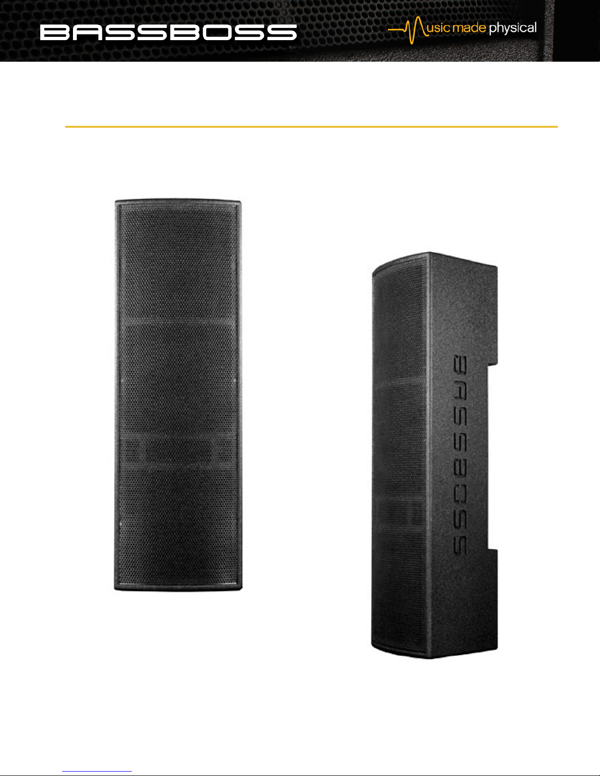
The AT312 Attuned Top is a co-axial point-source cabinet for
medium to short distance coverage where a small footprint and
very high fidelity are required. It’s compact, simple to use, easy
to set up, attractive and capable of very high output with
superbly uncolored sound and natural musical character.
When combined with subwoofers like the SSP218 Profundo Subwoofer or
ZV28 Profundo Sub, the result is an extremely high-resolution 4-way active
loudspeaker system with virtually unparalleled resolution and dynamic
power for its size. Its driver compliment incorporates dual 12” woofers in a
vented enclosure for low frequencies and a 12” midrange driver in a sealed
enclosure with a co-axially mounted 1.4” exit compression driver. Coverage
is 80 degrees conical. One-man set up of a substantial system is made easy
because the AT312 cabinets weigh only 88 lbs each.
Dual 12” low frequency drivers were chosen to minimize cabinet frontal area
while delivering the best possible speed and impact in their operating range.
Thanks to the narrow frontal area, the low frequency drivers couple
coherently when multiple cabinets are arrayed, providing powerful mid-bass
impact from a small, lightweight box.The 12” coaxial drivers also serve to
minimize frontal area while maximizing output. The loudspeaker behaves
as a point-source, which deliver more consistent off-axis performance than
conventional loudspeakers with separate mid and high frequency drivers.
This feature enhances resolution and the consistency also enhances the
loudspeaker's versatility, allowing it to be mounted horizontally or vertically
with no compromise in coverage or performance. The 48” tall box elevates
the mid and high frequency radiators to a minimum of 7’6” on center when
stacked on the corresponding subwoofer systems.
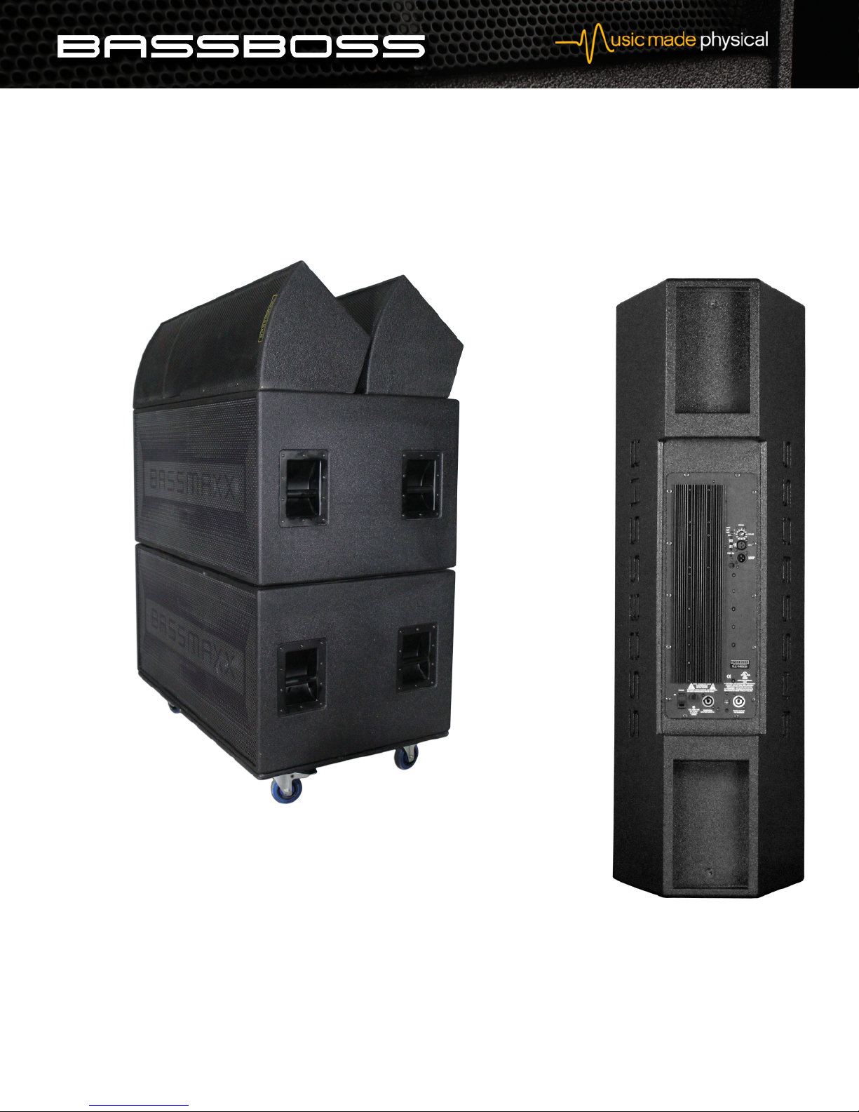
Transportation and set-up of the SSP218/AT312 combination is made easy
because the subwoofers serve as a carrier for the tops. In most venues
it’s possible to roll the system into place, lock the casters, tilt up the tops,
plug in the power and signal and have an extremely substantial system
ready to play in a few short minutes by just one person.
When an AT312 is used with a BASSBOSS powered subwoofer the result
is a very effective, practical, high fidelity 4-way active loudspeaker system.
The simplicity and ease of these components together, coupled with fidelity
and reliabilty that are industry leading,will delight anyone who is regularly
moving gear.
Any speaker that has the tweeter horizontally or vertically offset from the
mid-frequency driver produces very different response as one moves through
its coverage area from the tweeter side to the woofer side.This is due to the
different distances the sound has to travel to reach the ears. Due to the
co-axial construction of the AT312 the path length difference between lows
and highs is the same in any direction, allowing extremely consistent off-axis
response regardless of which direction you move away from directly on center.
AT312 Attuned Powered To
• Outstanding Sound Quality
• High-Output 3-Way Active Loudspeake
• Lightweight and Low-P ofile
• Symmet ical Cove age, Any O ientation
• With Subs Offe s 1 Pe son Set-Up La ge System

BASSBOSS At312 Attuned Top OWNER’S MANUAL
3
P ge
Performance
oudspeaker Description: Point-source mid-high cabinet with 80 degree conical coverage for horizontal or vertical applications
Frequency Response (±3 dB): 80 Hz – 18 kHz
Sensitivity: F: 100dB; MF: 96dB; HF:107dB
Maximum Sustained Output: 128 dB
Short-term peak Output: 131 dB
Input Power Rating: 2000W RMS
Nominal Dispersion (°H x °V): 80 x 80
Input Power Rating, F, MF, HF: 1400W, 800W, 160W
Enclosure Type: 3-way mid-high. Helmholz resonator F section, acoustic suspension MF section with co-axially mounted, horn-loaded HF section
ow Frequency Transducer: 2 x 12 " dia (300 mm) neodymium motor woofer with 3" (76 mm) voice coil, waterproof cone
Mid Frequency Transducer: 12" dia. (300 mm) neodymium motor midrange driver with co-axial HF exit
High Frequency Transducer: 1.4" exit 3' (76 mm) voice coil compression driver mounted to 80 degree conical wave guide
Output Power Rating, Channel 1: 1500W @ 4Ω
Output Power Rating, Channel 2: 750W @ 4 Ω
Output Power Rating, Channel 3: 600W @ 8 Ω
Compatible Subwoofers: BASSBOSS Motiv Bass Horn and Profundo Subwoofers
Electrical Input Connector: Neutrik Powercon
Voltage Operating Range: 90-250V. Auto-sensing, auto switching universal supply
Current Draw, Nominal: 3A @ 1/8 power
Current Draw, Peak: 20A
Signal Input Connector: X R-F
Signal Output Connector: X R-M pass-through only
DSP: Dual 24 bit 48kHz, 116 dB(A) signal to noise ratio with 4 presets
Amplification: Available with dedicated amplification for installation
Physical
Suspension System: 6 x 3/8-16tpi threaded flypoints
Side Pull Anchors: For use when flying cabinets horizontally
Shoulder Eye Bolts: For use when flying cabinets vertically
Cover: Heavy-duty padded nylon transport cover
Online Information: www.bassboss.com/at312
Cabinet Construction: 18mm Baltic Birch plywood, dado joinery, integrated handles,20 degree side angle trapezoid
Suspension System: 16 x 3/8"-16tpi threaded flypoints
Dimensions (HxWxD): 48" x 15"(f) x 14"
Net Weight Passive: 79 lbs.
Net Weight Active: 88 lbs.
Shipping Weight: 100 lbs.
Exterior finish: Weatherproof bonded polyurethane
Grill: Perforated, powder-coated steel
Power
O tional

PHOTOS
BASSBOSS At312 Attuned Top OWNER’S MANUAL
4
P ge

FREQUENCY RESPONSE GRAPH, DIMENSION DRAWINGS
BASSBOSS At312 Attuned Top OWNER’S MANUAL
Single Cabinet Response
Response with Subwoofer
5
P ge

SAFETY INFORMATION
Read with special attention, as they provide important information. Information regarding use of loudspeakers:
Never stand in the immediate vicinity of loudspeakers driven at a high level. Professional loudspeaker systems are capable of causing a sound
pressure level detrimental to human health. Seemingly non-critical sound levels (from approx. 95 dB SP ) can cause hearing damage if people are
exposed to it over a long period. To prevent potentially dangerous exposure to high levels of acoustic pressure, anyone who is exposed to these
levels should use adequate protection devices.
When a transducer capable of producing high sound levels is being used, it is therefore necessary to wear ear plugs or protective earphones.
See the manual technical specifications to know the maximum sound pressure level.
In order to prevent accidents when setting up the loudspeakers or loudspeaker stands, make sure they are standing on a firm surface.
Ensure that all additional hardware, fixings and fasteners used for installation or mobile deployment are of an appropriate size and load safety
factor.
Pay attention to the manufacturers' instructions and to the relevant safety guidelines.
Regularly check the loudspeaker housings and accessories for visible signs of wear and tear, and replace them when necessary.
Regularly check all load bearing bolts in the mounting devices.
Caution: oudspeakers produce a static magnetic field even if they are not connected or are not in use.Therefore make sure when erecting and
transporting loudspeakers that they are nowhere near equipment and objects which may be impaired or damaged by an external magnetic field.
Generally speaking, a distance of 0.5 m (1.5 ft) from magnetic data carriers (floppy disks, audio and video tapes, bank cards, etc.) is sufficient; a
distance of more than 1 m (3 ft) may be necessary with computer and video monitors.
Never attempt to carry out any operations, modifications or repairs that are not expressly described in this manual.
Contact your dealer or BASSBOSS support if the product is not functioning properly.
BASSBOSS strongly recommends this product is only installed by professional qualified installer who can ensure correct installation and certify it
according to the regulations in force.
The entire audio system must comply with the current standards and regulations regarding electrical systems.
IMPORTANT NOTES
To prevent the occurrence of noise on line signal cables, use screened cables only. All the precautions, in particular the safety ones, must be and
avoid putting them close to equipment that produces high-intensity electromagnetic fields, power cables and loudspeaker lines.
BASSBOSS At312 Attuned Top OWNER’S MANUAL
6
P ge

SET UP INSTRUCTIONS
1. Place loudspeaker in the desired location. Ensure that it is secure and stable.
2. Rotate the input attenuator knob counterclockwise to the lowest setting.
3. Connect signal via the XLR input jack.
4. Check voltage selection switch to ensure it is in the correct position for the AC line voltage being supplie . WARNING: Severe amage
will result if over 140V is applie while switch is in 115V position. If the voltage selection switch is in 230V position an 115V line voltage
is applie , no amage will occur however the unit will not power on.
5. Check that the Power switch is in the OFF position.
6. Connect the amplifier module’s power supply cord using the blue PowerCon™ connectors.To insert, align the
indexing tabs on the Powercon™ connector, insert it into the socket and rotate clockwise until the latch catches.
7. Connect the electrical plug to a power source.
8. Select the desired preset via the PGM SEL button.
9. Turn ON the power switch.
10. Check that the MUTE buttons are pressed IN to un-mute the channels.
11. Rotate the input attenuator clockwise to achieve the desired sound level.
The AT312 is equipped with 2 presets. The presets are selected using the PGM SEL button. The button has 2
positions, in for preset 1 and out for preset 2.The presets load into the DSP when the amplifier module is powered
on. Changing the preset select button position while the amplifier is in operation will NOT change the setting.To
change the setting, select the position for the desired preset and then power on the amplifier.
Preset 1 includes all the required processing for normal operation.It is recommended that preset 1 be used for initial
setup and under most operating conditions. Preset 2 offers increased high frequency output and is appropriate for
use where greater distances must be covered such as outdoors or in other locations where additional high frequency
content is desirable.
System Setup A en um:
hen connecting multiple loudspeakers in a system, signal can be passed through from one loudspeaker to another
using XLR cables. No processing is applied to the signal as it passes through from the input to the output connectors
in each loudspeaker. Signal can be routed in any sequence because each loudspeaker receives a full-range signal and
applies the necessary processing in order to operate as part of the overall system. It is recommended to run signal
to the nearest box first and patch to the next nearest box in sequence.
The AT312 is equipped with a power pass-through facility that allows multiple boxes to be connected on a single
power source. The total power draw of all units connected through one power input connector cannot exceed
20A.This limits the number of AT312s that can be connected on one power inlet to 2 when using 115V line voltage
and 4 when using 230V line voltage.
BASSBOSS At312 Attuned Top OWNER’S MANUAL
7
P ge

TROUBLESHOOTiNG
If after following the above instructions for setup you have no output from the
loudspeakers, please check the following:
Verify that the green power (PWR) ED is on. If not, check the following:
1. Is the power cord plugged into a live outlet?
2. Is the Neutrik Powercon connector rotated into the locked position?
3. Is the amplifier power switch on?
If the power ED is on, check the following:
Is the green “signal present” ED (SIG) illuminating? If not:
1. Is the signal cable connected to the input?
2. Is the signal cable connected to an operating output at the other end?
3. Is the signal flowing to the input? Check the integrity of the cable.
If the signal ED is illuminating:
1. Is the attenuator turned all the way down or at a very low level?
2. Are the mute buttons engaged? When the button is out, the channel is muted. Make sure
that the mute buttons are pressed IN for normal operation.The mute buttons are next to
the program select
(PGM SE ) button.
3. Is the signal flowing to the input full-range? Filters in the signal may remove the
operating frequencies of the loudspeaker receiving them. The signal ED will illuminate
at the presence of any signal so while high-frequency signal will illuminate the ED on a
subwoofer, no or very little sound will be heard.
BASSBOSS At312 Attuned Top OWNER’S MANUAL
8
P ge

BASSBOSS At312 Attuned Top OWNER’S MANUAL
Thanks for your BASSBOSS purchase!
WARRANTY INFORMATION
Beyond ensuring your satisfaction,our extensive "Sound Defense"transferable warranty which covers all BASSBOSS products.
STANDARD CABINET WARRANTY
BASSBOSS loudspeaker cabinet integrity,including all joinery,fasteners,handles and wood,is warranted against defects in materials and workmanship for a period
of six years from the date of purchase.This warranty does not cover items that are intended to wear and can be replaced if worn or damaged.Examples of items
not covered by this warranty are cabinet feet, grills and the finish or coating applied to the cabinet.
ENHANCED COM ONENT WARRANTY
BASSBOSS self-powered loudspeaker amps and electronic components are covered against failures due to defects in materials and/or workmanship for a period
of three years from the date of purchase. Speaker drivers and burned or open voice coils in subwoofers are covered for two years.
OUR SU ORT
It is our goal to provide trouble-free loudspeakers.That objective begins as part of the design phase and continues on through to any service you may require.
In order to be able to provide the lowest possible failure rate, the best possible warranty service and the fastest turn-around time,we request that you contact
us immediately if you notice any problem with your system, and before you attempt any repairs. We can provide the best and fastest solution if we know the
details of the problem before any repair attempts are made. Often BASSBOSS technicians can troubleshoot problems that may arise and no repair or further
service will be necessary.
Warranty support is a service,and part of that service includes helping you prevent failures and minimize repair and shipping costs.Please do not ship products
without first obtaining a return authorization number by calling 512-368-3268 (855-822-7770 toll-free) or by emailing suppor[email protected]. BASSBOSS
service technicians will provide assistance and instructions on shipping and packaging requirements specific to your service needs.
WARRANTY LIMITATIONS
During the warranty period, if your loudspeaker malfunctions or fails due to any defect in components or manufacturing, the failed parts will be repaired or
replaced.This warranty does not extend to damage resulting from improper installation, misuse, neglect or abuse. Warranty coverage will be determined upon
inspection by BASSBOSS personnel. This warranty does not cover labor other than that authorized and performed by BASSBOSS personnel. Service will be
performed upon the return of the failed unit, together with its original sales receipt or other proof of purchase, to BASSBOSS or an Authorized Service Facility.
Purchaser is responsible for all costs of shipping and handling. Cosmetic damage is specifically excluded from this warranty. This warranty is rendered void if
service,repairs and/or modifications are attempted or made by anyone not specifically authorized byBASSBOSS to perform said services.Please contact BASSBOSS
or your local BASSBOSS dealer before attempting any repairs and before shipping parts in for service.
This warranty gives you specific legal rights, and you may also have other rights, which vary from state to state. For more information concerning BASSBOSS
service and warranty policies please contact us at 512-36-3268 or (855) 822-7770 toll-free.
EX ORT WARRANTY
BASSBOSS products can be purchased worldwide. In countries without local BASSBOSS distributors, product requiring service must be shipped back to the US
for warranty repairs. In most cases, the entire cabinet will not need to be shipped. Generally only the individual affected parts will need to be shipped to the
factory for servicing. Please contact BASSBOSS before attempting any repairs and before shipping parts in for service.
SHI ING AND ACKAGING
Please package your returns safely and securely. BASSBOSS does not cover damage that occurs in transit.Freight insurance is recommended.
9
P ge

FCC COM LIANCE NOTICE
This device complies with part 15 of the FCC rules. Operation is subject to the following two conditions: (1) This device may
not cause harmful interference, and (2) this device must accept any interference received, including interference that may
cause undesired operation.
CAUTION: Changes or modifications not expressly approved by the party responsible for compliance could void the user’s
authority to operate the equipment.
NOTE: This equipment has been tested and found to comply with the limits for a Class B digital device, pursuant to part 15
of the FCC Rules. These limits are designed to provide reasonable protection against harmful interference in a residential
installation. This equipment gener- ates, uses, and can radiate radio frequency energy and, if not installed and used in
accordance with the instruction manual, may cause harmful interference to radio communications. However, there is no
guarantee that interference will not occur in a particular installation. If this equipment does cause harmful interference to
radio or television reception,which can be determined by turning the equipment off and on, the user is encouraged to try to
correct the interference by one or more of the following measures:
• Reorient or relocate the receiving antenna.
• Increase the separation between the equipment and receiver.
• Connect the equipment into an outlet on a circuit different from that to which the receiver is connected.
• Consult the dealer or an experienced radio/TV technician for help.
EC DECLARATION OF CONFORMITY
Manufacturer:
BASSBOSS 9501 Cargo Ave Ste 600 Austin TX 78719
We declare that under our sole responsibility the product: AT312 Powered Top Speaker
Intended use: Professional Audio oudspeaker
Are in conformity with the provisions of the following EC Directives,including all amendments, and with national legislation
implementing these directives:
• 2006/95/EC ow Voltage Directive
• 2004/108/EC Electromagnetic Compatibility Directive
• 2002/95/CE RoHs Directive
BASSBOSS At312 Attuned Top OWNER’S MANUAL
10
P ge
Other manuals for AT312 Attuned Top
2
Table of contents
Other BassBoss Speakers manuals

BassBoss
BassBoss AT312 Attuned Top User manual

BassBoss
BassBoss AT212-MK3 User manual

BassBoss
BassBoss MicroMain SV9 User manual

BassBoss
BassBoss DIAMON-MK3 User manual

BassBoss
BassBoss DV12-MKII User manual

BassBoss
BassBoss AT312-MK3 User manual

BassBoss
BassBoss DV12-MK3 User manual

BassBoss
BassBoss AT212 Powered MicroMain User manual

BassBoss
BassBoss MK3 Series User manual

BassBoss
BassBoss DV12 User manual