Batavia MAXXPACK BT-CMS001 User manual

Model: BT–CMS001
Item-No.: 7063453
www.batavia.eu
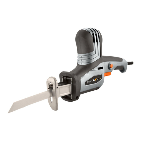
Cordless sliding mitre saw
Akku-Zug-Kapp-Gehrungssäge
Scie à onglet radiale sans l
Accu radiaal afkort- en verstekzaag
Troncatrice radiale senza li
Sierra ingletadora deslizante inalámbrica
Serra meia-esquadria deslizante sem os
Bezprzewodowa piła ukosowa z funkcją przesuwu
Operating instructions
Bedienungsanleitung (Original)
Mode d'emploi
Gebruiksaanwijzing
Istruzioni di Funzionamento
Manual de usuario
Instruções de funcionamento
Instrukcja
PACK 18 V

2
9
10
5
25
24
13
12
15
26
8
23
14
11
1
2
3
18
19
16
22
20
21
17
7
6
4
5
A

3
Overview
1. Main handle
2. Saw blade guard
3. Saw blade
4. Workpiece clamp
5. Mitre position lock knob
6. Workpiece stop
7. Workpiece support
8. Bevel angle indicator
9. Bevel position lock knob
10. Carrying handle
11. Dust extraction ange
12. Depth of cut adjustment
13. Battery slot
14. Laser ON/OFF switch
15. LED worklight ON/OFF switch
16. Safety catch
17. ON/OFF switch
18. Saw head locking pin
19. Sliding lock screw
20. Rear fence
21. Work support lock screw
22. Turn table
23. Mitre angle indicator
24. Support foot
25. Spindle lock button
26. LED worklight and laser
Übersicht
1. Hauptgriff
2. Schutzhaube des Sägeblattes
3. Sägeblatt
4. Werkstückklemme
5. Drehknopf der Gehrungseinstellung
6. Werkstückanschlag
7. Werkstückstütze
8. Zeiger des Fasenwinkels
9. Drehknopf der Fasenwinkel-verstellung
10. Tragegriff
11. Staubabsaugansch
12. Schnitttiefeneinstellung
13. Akkuaufnahme
14. Laser EIN/AUS Schalter
15. EIN/AUS Schalter der LED
Arbeitsleuchte
16. Sicherheitstasten
17. EIN/AUS Schalter
18. Verriegelungsstift des Sägekopfes
19. Zugklemmschraube
20. Hinterer Anschlag
21. Klemmschraube der Werkstückstütze
22. Drehtisch
23. Zeiger der Gehrungseinstellung
24. Stützfuß
25. Wellensperre
26. LED Arbeitsleuchte und Laser
B
C
18 V
⎓
Li-Ion
Cordless sliding mitre saw
Model: BT-CMS001 • Art.-Nr.: 7063453 • S/N: ______ 19X
n0: 4200min-1 • Cutting capacity:
0° / 0°: 62 × 305 mm
0° / 45°: 62 × 210 mm
45° / 0°: 30 × 305 mm
45° / 45°: 30 × 210 mm
7063453/2
Batavia GmbH, Weth. Wassebaliestraat 6d,
NL-7951 SN Staphorst, Netherlands
EN 60825-1:2015-07
Strahlungsleistung /
Optical Power:
P ≤ 1 mW
Wellenlänge /
Wavelength (λ): 650 nm
LASERSTRAHLUNG
NICHT IN DEN STRAHL BLICKEN
LASER KLASSE 2
LASER RADIATION
DO NOT STARE INTO BEAM
LASER CLASS 2

4
Aperçu
1. Poignée principale
2. Protecteur de lame de scie
3. Lame de scie
4. Pince de serrage de la pièce
5. Bouton de verrouillage de la position
d’onglet
6. Butée de la pièce
7. Support de la pièce
8. Indicateur de l’angle de biseau
9. Bouton de verrouillage de la position de
biseau
10. Poignée de transport
11. Bride d’aspiration de poussière
12. Réglage de la profondeur de coupe
13. Emplacement pour pile
14. Commutateur laser MARCHE/ARRÊT
15. Interrupteur MARCHE/ARRÊT de la
lampe de travail à LED
16. Verrou de sécurité
17. Commutateur MARCHE/ARRÊT
18. Broche de verrouillage pour tête de scie
19. Vis de verrouillage coulissant
20. Guide arrière
21. Vis de verrouillage du support de la
pièce
22. Table tournante
23. Indicateur de l’angle d’onglet
24. Pied d’appui
25. Bouton de verrouillage de la broche
26. Lampe de travail à LED et laser
Overzicht
1. Hoofdhandgreep
2. Beschermkap zaagblad
3. Zaagblad
4. Werkstukklem
5. Vergrendelknop afkortstand
6. Stop voor werkstuk
7. Werkstuksteun
8. Schuine hoekindicator
9. Vergrendelknop schuine stand
10. Draaghandgreep
11. Flens voor stofafzuiging
12. Afstelling zaagdiepte
13. Sleuf voor accu
14. Aan-/uitschakelaar laser
15. Aan-/uitschakelaar led-werkverlichting
16. Veiligheidspal
17. Aan-/uitschakelaar
18. Vergrendelpen zaagkop
19. Borgschroef schuiven
20. Achterste stuitplaat
21. Borgschroef werksteun
22. Draaitafel
23. Indicator afkorthoek
24. Steunvoet
25. Spindelvergrendknop
26. Led-werkverlichting en laser

5
Panoramica
1. Impugnatura principale
2. Protezione della lama
3. Lama
4. Morsetto di ssaggio del pezzo da
lavorare
5. Manopola di blocco della posizione
della troncatrice
6. Fermo del pezzo da lavorare
7. Supporto del pezzo da lavorare
8. Indicatore dell’angolo di smussatura
9. Manopola di blocco della posizione di
smussatura
10. Maniglia per il trasporto
11. Flangia di aspirazione della polvere
12. Regolazione della profondità di taglio
13. Slot per batteria
14. Interruttore di accensione/spegnimento
del laser
15. Interruttore di accensione/spegnimento
della luce da lavoro LED
16. Fermo di sicurezza
17. Interruttore accensione/spegnimento
18. Perno di bloccaggio della testa della
sega
19. Vite di bloccaggio scorrevole
20. Barriera posteriore
21. Vite di bloccaggio del supporto di
lavoro
22. Base girevole
23. Indicatore dell’angolo di troncatura
24. Piede di supporto
25. Pulsante di blocco del mandrino
26. Luce da lavoro LED e laser
Resumen
1. Empuñadura principal
2. Protector de la hoja de sierra
3. Hoja de sierra
4. Sargento para la pieza de trabajo
5. Clavija de bloqueo de la posición del
inglete
6. Tope para la pieza de trabajo
7. Soporte para la pieza de trabajo
8. Calibrador del ángulo de bisel
9. Clavija de bloqueo de la posición del
bisel
10. Empuñadura de transporte
11. Base de acople para la extracción de
polvo
12. Ajuste de la profundidad del corte
13. Ranura para la batería
14. Interruptor de encendido/apagado del
láser
15. Interruptor de encendido/apagado de la
lámpara led de trabajo
16. Cierre de seguridad
17. Interruptor de encendido/apagado
18. Seguro del cabezal de la sierra
19. Tornillo de bloqueo del deslizamiento
20. Pantalla trasera
21. Tornillo de bloqueo del soporte de
trabajo
22. Placa giratoria
23. Calibrador del ángulo en inglete
24. Pie de apoyo
25. Seguro del eje
26. Lámpara led de trabajo y láser

6
Visão geral
1. Pega principal
2. Guarda da lâmina de serra
3. Lâmina da serra
4. Fixador da peça de trabalho
5. Manípulo de bloqueio da posição de
chanfro
6. Batente da peça de trabalho
7. Suporte da peça de trabalho
8. Indicador do ângulo de biselado
9. Manípulo de bloqueio da posição de
biselado
10. Pega de transporte
11. Flange de extração de pó
12. Ajuste da profundidade de corte
13. Ranhura da bateria
14. Interruptor de ligar/desligar de laser
15. Interruptor de ligar/desligar da luz de
trabalho LED
16. Base de segurança
17. Interruptor de LIGAR/DESLIGAR
18. Pino de bloqueio da cabeça da serra
19. Parafuso de bloqueio deslizante
20. Barreira traseira
21. Parafuso de bloqueio de suporte de
trabalho
22. Mesa giratória
23. Indicador do ângulo de chanfro
24. Base de apoio
25. Botão de bloqueio do fuso
26. Luz de trabalho LED e laser
Przegląd
1. Uchwyt główny
2. Osłona tarczy piły
3. Tarcza piły
4. Zacisk obrabianego przedmiotu
5. Pokrętło blokady ustawienia skosu
6. Ogranicznik obrabianego przedmiotu
7. Wspornik obrabianego przedmiotu
8. Wskaźnik kąta ukosu
9. Pokrętło blokady ustawienia ukosu
10. Uchwyt do przenoszenia
11. Kołnierz odprowadzania pyłu
12. Regulacja głębokości cięcia
13. Gniazdo akumulatora
14. Włącznik lasera
15. Włącznik roboczej lampki LED
16. Zapadka bezpieczeństwa
17. Włącznik/wyłącznik
18. Kołek blokady głowicy piły
19. Śruba blokady przesuwu
20. Tylna prowadnica
21. Śruba blokująca wspornik obrabianego
przedmiotu
22. Stół obrotowy
23. Wskaźnik kąta skosu
24. Podpórka pomocnicza
25. Przycisk blokady wrzeciona
26. Lampka robocza LED i laser

7
Contents
1. Explanation of the symbols . . . . 9
2. Additional safety warnings . . . . 9
3. Special safety notes for crosscut and
mitre saws . . . . . . . . . 9
4. Safety instructions for mitre saws . .10
5. Before the rst use . . . . . .11
6. Contents of packing . . . . . .11
7. Intended use . . . . . . . .12
8. Assembly and adjusting instructions 12
9. Use . . . . . . . . . . .13
10. Cleaning and maintenance . . . .14
11. Technical data. . . . . . . .14
12. Disposal . . . . . . . . .14
13. EC-Declaration of conformity . . .15
Inhaltsverzeichnis
1. Erläuterung der Symbole . . . .16
2. Zusätzliche Sicherheitshinweise . .16
3. Spezische Sicherheitshinweise für
Kapp- und Gehrungssägen . . . .17
4. Spezielle Sicherheitshinweise . . .17
5. Vor der ersten Benutzung . . . .19
6. Verpackungsinhalt . . . . . .19
7. Bestimmungsgemäßer Gebrauch . .19
8. Zusammenbau . . . . . . .19
9. Gebrauch . . . . . . . . 20
10. Reinigung und Wartung . . . . 22
11. Technische Daten. . . . . . 22
12. Entsorgung . . . . . . . 22
13. EG-Konformitätserklärung . . . 22
Table des matières
1. Explication des symboles . . . 23
2. Avertissements de sécurité
additionnels . . . . . . . 23
3. Avertissements spéciques pour les
scies à tronçonner et à onglets . . 24
4. Consignes de sécurité particulières 24
5. Avant la première utilisation. . . 26
6. Contenus de l’emballage. . . . 26
7. Utilisation prévue . . . . . . 26
8. Instructions de montage et de
réglage . . . . . . . . . 26
9. Utilisation . . . . . . . . 27
10. Nettoyage et maintenance . . . 29
11. Caractéristiques techniques . . 29
12. Élimination et recyclage . . . . 29
13. CE-Déclaration de conformité . . 30
Inhoudsopgave
1. Uitleg van de symbolen . . . . 31
2. Aanvullende veiligheidsvoorschriften 31
3. Speciale veiligheidsaanwijzingen
voor afkortzagen . . . . . . 32
4. Speciale veiligheidsvoorschriften . 32
5. Voor het eerste gebruik . . . . 34
6. Inhoud van de verpakking . . . 34
7. Beoogd gebruik . . . . . . 34
8. Instructies voor montage en
afstelling . . . . . . . . 34
9. Gebruik . . . . . . . . . 35
10. Reiniging en onderhoud . . . . 36
11. Technische gegevens: . . . . 37
12. Afvalverwerking en hergebruik . . 37
13. EG-Conformiteitsverklaring . . . 37

8
Contenuto
1. Spiegazione dei simboli . . . . 38
2. Ulteriori avvertenze di sicurezza . 38
3. Note speciche per un uso sicuro
delle troncatrici radiali e delle seghe
circolari. . . . . . . . . 39
4. Istruzioni di sicurezza per le
troncatrici radiali . . . . . . 39
5. Operazioni preliminari al primo uso
del prodotto . . . . . . . 41
6. Contenuto della confezione . . . 41
7. Destinazione d'uso . . . . . 41
8. Istruzioni di montaggio e regolazione 41
9. Uso . . . . . . . . . . 42
10. Pulizia e manutenzione . . . . 44
11. Dati tecnici . . . . . . . . 44
12. Smaltimento . . . . . . . 44
13. Dichiarazione di conformità CE . . 45
Índice
1. Explicación de los símbolos. . . 46
2. Advertencias de seguridad
adicionales. . . . . . . . 46
3. Instrucciones especiales de
seguridad relativas a las sierras
tronzadoras y las sierras
ingletadoras . . . . . . . 47
4. Instrucciones de seguridad en
materia de sierras ingletadoras. . 47
5. Antes de usar por primera vez . . 49
6. Contenido del paquete . . . . 49
7. Uso previsto . . . . . . . 49
8. Instrucciones de ensamblaje y ajuste 49
9. Uso . . . . . . . . . . 50
10. Limpieza y mantenimiento . . . 52
11. Datos técnicos . . . . . . 52
12. Eliminación . . . . . . . 52
13. Declaración CE de conformidad . 53
Índice
1. Explicação dos símbolos . . . 54
2. Avisos de segurança adicionais . 54
3. Notas de segurança especiais para
serras de traçar e meia-esquadria . 55
4. Instruções de segurança para serras
meia-esquadria . . . . . . 55
5. Antes da primeira utilização. . . 57
6. Conteúdo da embalagem . . . 57
7. Utilização prevista . . . . . 57
8. Montagem e instruções de ajuste . 57
9. Utilização . . . . . . . . 58
10. Limpeza e manutenção . . . . 60
11. Dados técnicos . . . . . . 60
12. Eliminação . . . . . . . . 60
13. Declaração de conformidade CE . 61
Spis treści
1. Objaśnienie symboli . . . . . 62
2. Dodatkowe zalecenia dotyczące
bezpieczeństwa . . . . . . 62
3. Specjalne środki ostrożności
dotyczące pił poprzecznych i
ukosowych. . . . . . . . 63
4. Zalecenia dotyczące bezpiecznego
korzystania z pił ukosowych . . 63
5. Przed pierwszym użyciem . . . 65
6. Zawartość opakowania . . . . 65
7. Przeznaczenie. . . . . . . 65
8. Instrukcja montażu i regulacji . . 65
9. Sposób użycia. . . . . . . 66
10. Czyszczenie i konserwacja . . . 68
11. Dane techniczne . . . . . . 68
12. Utylizacja . . . . . . . . 68
13. Deklaracja zgodności z
wymogami UE. . . . . . . 69

9
English
Dear customer
Please familiarize yourself with the proper
usage of the device by reading and following
each chapter of this manual, in the order
presented. Keep these operating instruc-
tions for further reference.
Please read the enclosed “General safety
instructions for power tools” and all
additional safety instructions in this
operating instructions!
This manual contains important information
on operating and handling the device. Keep
these operating instructions for further
reference. Please pass it on along with the
unit if it is handed over to a third party.
Battery and charger not included!
The battery is available separately under
art.No: 7062518 (4Ah). The charger is avail-
able separately under art.No: 7063630
(1.65A) or 7063554 (4A).
These items are available online and in par-
ticipating stores.
1. Explanation of the symbols
The following symbols are used in the user
manual or on the product:
Warning! To reduce the risk of
injury, the user must read the
instruction manual.
Denotes risk of personal injury,
loss of life or damage to the tool in
case of non-observance of the
instructions in this manual.
Always wear hearing protection.
The effects of noise can cause
hearing loss.
Wear a dust mask. When working
with wood and other materials,
harmful dust may be generated.
Work with asbestos containing materials
is not permitted!
Wear safety glasses. When work-
ing with electric power tools,
sparks, splinters, chips and dust
particles may be generated and these can
cause loss of sight.
Caution: Laser beam! Do not look
directly into the laser beam. Do
not point the laser beam at
humans or animals.
CE stands for “Conformité
Européenne”, which means “In
accordance with EU Regula-
tions”. With the CE marking, the manufac-
turer conrms that this Electric tool com-
plies with the applicable European
directives.
Do not dispose of electric power
tools with domestic refuse.
2. Additional safety warnings
Please note the included General
Safety Notes and the following
safety notes to avoid malfunc-
tions, damage or physical injury:
2.1 Please read this manual carefully and
use the unit only according to this
manual.
2.2 (See Fig. B) Never point the laser at
persons or animals. At every time hold
the unit in that way that the laser beam
is directed to radiate away from the
body. Never stare into the laser beam. It
can cause severe eye injuries. Do not
point the laser at mirrors or other
strongly reecting surfaces. The uncon-
trolled deected beam may hit persons
or animals.
2.3 The unit is not a toy and does not
belong in the hands of children. Never
leave the unit unsupervised when in
use. Keep it out of reach of children or
persons in need of supervision. Children
should be supervised to ensure that
they do not play with the unit.
2.4 Persons with limited physical, sensorial
or mental abilities are not allowed to
use the machine, unless they are super-
vised and briefed for their safety by a
qualied person.
2.5 Should the unit become damaged do
not use it any further and have it
repaired by a professional or contact
our customer service. Do not disassem-
ble the unit or try repairing it yourself.
3. Special safety notes for crosscut
and mitre saws
3.1 Always use the correct saw blade for
the material you intend to cut.

English
10
3.2 Do not use damaged or warped saw
blades.
3.3 Worn base plate inserts must be
replaced.
3.4 Use only saw blades which are recom-
mended by the manufacturer and corre-
spond to EN 847-1. Do not use HSS saw
blades.
3.5 If necessary, wear suitable protective
equipment. These are ear protection,
safety goggles, a dust mask and gloves
to protect your hands when handling
saw blades or coarse materials. (Saw
blades must, whenever possible, be
carried in a container). Please keep in
mind that wearing Gloves while operat-
ing the saw is a safety risk and should
not be done.
3.6 When cutting wood, always connect the
mitre saw to a dust extractor.
3.7 Keep your hands and other body parts
away from the rotating saw blade.
3.8 Secure all work pieces with the screw
clamp on the saw.
3.9 Before startling a cut, lock the mobile
base plate and the pivoting arm.
3.10 The ground around the machine should
be even, clean and free from debris
such as scrap pieces.
3.11 Use only sharp, straight saw blades in
good condition. Please observe the
maximum revolution speed of the saw
blade.
3.12 Do not reach unto the working area to
remove pieces or for any other reason
while the machine is running and the
saw assembly is not locked into the
resting position.
3.13 Make sure the machine is, if possible,
solidly mounted or clamped to a work-
bench or table.
3.14 Long work pieces should by all means
be supported with an additional support
such as a roller support.
3.15 Make sure there are no nails, screws or
similar items in the work piece.
3.16 Periodically check all nuts, bolts and
other xings and tighten where
necessary.
4. Safety instructions for mitre
saws
a. Mitre saws are intended to cut wood
or wood-like products, they cannot be
used with abrasive cut-off wheels for
cutting ferrous material such as bars,
rods, studs, etc. Abrasive dust causes
moving parts such as the lower guard
to jam. Sparks from abrasive cutting
will burn the lower guard, the kerf insert
and other plastic parts.
b. Use clamps to support the workpiece
whenever possible. If supporting the
workpiece by hand, you must always
keep your hand at least 100 mm from
either side of the saw blade. Do not
use this saw to cut pieces that are too
small to be securely clamped or held
by hand. If your hand is placed too
close to the saw blade, there is an
increased risk of injury from blade
contact.
c. The workpiece must be stationary and
clamped or held against both the
fence and the table. Do not feed the
workpiece into the blade or cut “free-
hand” in any way. Unrestrained or mov-
ing workpieces could be thrown at high
speeds, causing injury.
d. Push the saw through the workpiece.
Do not pull the saw through the work-
piece. To make a cut, raise the saw
head and pull it out over the workpiece
without cutting, start the motor, press
the saw head down and push the saw
through the workpiece. Cutting on the
pull stroke is likely to cause the saw
blade to climb on top of the workpiece
and violently throw the blade assembly
towards the operator.
e. Never cross your hand over the
intended line of cutting either in front
or behind the saw blade. Supporting
the workpiece “cross handed” i.e. hold-
ing the workpiece to the right of the saw
blade with your left hand or vice versa is
very dangerous.
f. Do not reach behind the fence with
either hand closer than 100 mm from
either side of the saw blade, to remove
11
English
wood scraps, or for any other reason
while the blade is spinning. The prox-
imity of the spinning saw blade to your
hand may not be obvious and you may
be seriously injured.
g. Inspect your workpiece before cutting.
If the workpiece is bowed or warped,
clamp it with the outside bowed face
toward the fence. Always make certain
that there is no gap between the work-
piece, fence and table along the line of
the cut. Bent or warped workpieces can
twist or shift and may cause binding on
the spinning saw blade while cutting.
There should be no nails or foreign
objects in the workpiece.
h. Do not use the saw until the table is
clear of all tools, wood scraps, etc.
except for the workpiece. Small debris
or loose pieces of wood or other objects
that contact the revolving blade can be
thrown with high speed.
i. Cut only one workpiece at a time.
Stacked multiple workpieces cannot be
adequately clamped or braced and may
bind on the blade or shift during cutting.
j. Ensure that the mitre saw is mounted
or placed on a level, rm work surface
before use. A level and rm work sur-
face reduces the risk of the mitre saw
becoming unstable.
k. Plan your work. Every time you change
the bevel or mitre angle setting, make
sure the adjustable fence is set cor-
rectly to support the workpiece and
will not interfere with the blade or the
guarding system. Without turning the
tool “ON” and with no workpiece on the
table, move the saw blade through a
complete simulated cut to assure there
will be no interference or danger of
cutting the fence.
l. Provide adequate support such as
table extensions, saw horses, etc. for
a workpiece that is wider or longer
than the table top. Workpieces longer
or wider than the mitre saw table can tip
if not securely supported. If the cut-off
piece or workpiece tips, it can lift the
lower guard or be thrown by the spin-
ning blade.
m. Do not use another person as a sub-
stitute for a table extension or as
additional support. Unstable support
for the workpiece can cause the blade
to bind or the workpiece to shift during
the cutting operation pulling you and
the helper into the spinning blade.
n. The cut-off piece must not be jammed
or pressed by any means against the
spinning saw blade. If conned, i.e.
using length stops, the cut-off piece
could get wedged against the blade and
thrown violently.
o. Always use a clamp or a xture
designed to properly support round
material such as rods or tubing. Rods
have a tendency to roll while being cut,
causing the blade to “bite” and pull the
work with your hand into the blade.
p. Let the blade reach full speed before
contacting the workpiece. This will
reduce the risk of the workpiece being
thrown.
q. If the workpiece or blade becomes
jammed, turn the mitre saw off. Wait
for all moving parts to stop and dis-
connect the plug from the power
source and/or remove the battery
pack. Then work to free the jammed
material. Continued sawing with a
jammed workpiece could cause loss of
control or damage to the mitre saw.
r. After nishing the cut, release the
switch, hold the saw head down and
wait for the blade to stop before
removing the cut-off piece. Reaching
with your hand near the coasting blade
is dangerous.
5. Before the rst use
Remove the machine and all accessories
from the package. Keep the packaging
materials out of the reach of small children.
There is a danger of suffocation!
6. Contents of packing
1× Cordless sliding mitre saw
1× Dust collection bag
1× 216mm 48 teeth saw blade (assembled)
2× Sets extension bars
1× Instruction manual

English
12
7. Intended use
The Mitre Saw is intended as a machine for
making straight cuts in wood, without the
need for a main power supply. It is possible
to cut mitre angles of -45° to +45° and bevel
angles of 0° to 45°. The Mitre Saw is
designed with sufcient capacity for sawing
hardwood and softwood.
8. Assembly and adjusting
instructions
8.1 Assembly
Insert the workpiece supports (7) into the
holes on either side of the mitre saw.
Tighten the workpiece support lock screws
(21) to lock the work supports in position.
Check that the supports are rmly held. The
mitre saw is delivered with a saw blade.
8.2 Operation
The mitre saw must be secured to a work-
bench or saw table. Check all covers and
safety devices have been properly tted and
are operational.
Check the saw head is not locked and is
free to move. If not free, disengage sliding
locking screw (19) and head down locking
pin (18). Before inserting the battery (13)
check that the saw blade (3) is free to
rotate.
8.3 Dust extraction
The saw dust collection bag or suitable saw
dust extraction system must be connected
to the saw dust extraction port (11).
8.4 Inserting and removing the battery
pack
Warning: Before inserting or removing the
battery pack, make sure the mitre saw is
switched off.
Please note that the saw will only work
correctly with the 4.0 Ah Battery.
Slide the battery pack into battery slot at the
rear of the saw head. To insert the battery
pack, align the battery pack with the battery
base at the rear of the saw head and slide
the battery pack into the saw so that the
battery pack is locked in position.
To remove the battery pack, press the bat-
tery’s release button and pull the battery
pack off at the same time.
8.5 Laser beam
Warning! Laser radiation! Observe the
safety notes! Laser class 2. The laser
beam is used to show the position of the
cut on the work-piece. It can be turned on or
off using the switch (14) on the top of the
saw body.
8.6 Led worklight
To provide additional lighting of the work-
piece the saw has a built-in LED worklight. It
can be turned on or off using the switch
(15) on the top of the saw body.
8.7 Setting the cutting angles
Warning! Before making any adjustments to
the settings, check that the battery has
been removed to prevent accidental
starting.
After setting the angles always perform test
cuts.
8.8 Setting the mitre angle
The mitre angle is left/right steplessly varia-
ble between 0° and 45°. To set the mitre
angle loosen the mitre position lock
knob(5). Rotate the table and set the
required mitre angle using the scale of the
mitre angle indicator (23). Tighten the mitre
position lock knob (5).
8.9 Setting the bevel angle
The bevel angle is steplessly variable
between 0° and 45°. To set the bevel Angle
and loosen the bevel position lock knob (9).
Tilt the cutting head to the desired required
bevel angle using the scale of the bevel
angle indicator (8). Tighten the bevel posi-
tion lock knob (9).
8.10 Setting cutting depth
The cutting depth can be adjusted if
required. To do so, set the sliding lock piece
to the forward position, so the depth of cut
adjustment screw (12) makes contact with
it when the saw head is pressed down.
Loosen the locking nut on the depth of cut
adjustment screw (12). Gently lower the
saw head to desired cutting depth. Adjust
the screw up or down for the desired depth
of cut. Re-tighten the locking nut on the
depth of cut adjustment (12).

13
English
9. Use
9.1 Cutting
Ensure a 4.0 Ah battery is charged and is
tted correctly.
Secure the workpiece with the clamp (4).
Carefully stay away from the spinning saw
blade. Make sure the saw blade cannot
touch any of the fences and adjust the
fences if necessary.
If you intend to cut a curved work piece,
make sure the work piece is not bent
against the fence. (See Fig. C.) Make sure
no gap forms between the work piece, the
fence and the base plate.
Long workpieces must be supported in a
suitable way, e.g. on a support equipped
with rollers. Avoid holding or guiding work-
pieces in a way which compromises your
balance.
To cut, press one of the safety catches (16)
and operate the ON/OFF switch (17). Allow
the saw blade to reach full speed before
gently pressing down the head of the saw.
When the machine has reached full speed,
press down the upper part of the saw by the
handle. Whenever possible, cut through the
workpiece with a single, even motion. Irreg-
ularly shaped workpieces can cause the
upper part to kick back up unexpectedly,
therefore hold the handle with a rm grip. To
stop the saw, release the ON/OFF
switch(17).
9.2 Compound cuts
Compound cuts can be made by setting any
combination of mitre, bevel and cutting
depth at the same time.
9.3 Drop cuts
Warning! Make sure the workpiece is rmly
clamped down to the base plate and is sup-
ported against the rear fence (20) before
cutting.
This cut is used where the width of the
workpiece is narrower than the cutting
width of the blade at the rearmost position.
Push the saw head back toward the guide
fence (20) fully and tighten the sliding lock
screw (19).
Turn the saw ON and wait for the blade to
reach full speed. Gently lower the saw head
towards the workpiece until the cut is
achieved. Do not force the blade. After com-
pletion of the cut, turn the saw OFF.
9.4 Sliding cuts
Warning! Make sure the workpiece is rmly
held or clamped down to the turn table (22)
and is supported against the rear fence (20)
before cutting.
Warning! A warped or irregular workpiece
may pinch the saw blade while being cut
and cause kickback. Check that the work-
piece is always evenly supported against
the rear fence (20).
This cut is used where the width of the
workpiece is wider than the cutting width of
the blade at the rearmost position.
Check that the saw is in the rearmost posi-
tion and check that the sliding lock screw
(19) is not engaged.
With the saw head in the up position, draw
the saw head out so it clears the workpiece.
Turn the saw ON and wait for the blade to
reach full speed. Gently lower the saw head
towards the workpiece until the depth of cut
is achieved. Do not force the blade. Once
the depth of cut is achieved hold the saw
head at this depth and push the saw head
towards the rearmost position to complete
the cut. Do not force the blade. After com-
pletion of the cut, turn the saw OFF.
9.5 Replacing the saw blade
Warning! Before replacing the saw blade
always remove the battery. Only use saw
blades with a speed rating of 4200 rpm or
greater. Make sure that the spindle diameter
and the saw blade bore match. Only use
sharp and undamaged saw blades. Cracked
or bent saw blades must be replaced
immediately.
Warning! Even used saw blades are sharp.
There is a risk of cuts while handling them.
Handle saw blades carefully.
Make sure that the battery has been
removed.
Place the head of the machine in its highest
position. Manually retract the lower guard to
expose the saw blade. Depress and hold the
spindle lock button (25) whilst rotating the
saw blade by hand until the spindle lock
button fully engages.

English
14
While keeping the spindle lock depressed,
place the supplied hex spanner onto the
spindle screw. Loosen the spindle screw
and remove it by turning it clockwise. Open
the saw blade cover manually and remove
the outer ange, the old saw blade, and the
inner ange.
Clean the anges with a piece of cloth. Ret
the inner ange. Fit the new saw blade with
the direction arrow corresponding to the
arrow on the housing. Ret the outer ange,
insert the spindle screw and nger tighten.
Depress and hold the spindle lock button
whilst rotating the saw blade by hand until
the spindle lock button fully engages.
Re-tighten the spindle screw using the sup-
plied hex wrench by turning it
counter-clockwise.
Check the operation of all guards and make
sure the saw blade is tight and is running
free and true.
9.6 Carrying handle
The saw is equipped with a carrying han-
dle(10). When carrying the saw secure the
saw head in its lowered position with the
locking pin(18).
10. Cleaning and maintenance
10.1 Cleaning
• Keep safety devices, ventilation open-
ings and the motor housing as free as
possible from dirt and dust. Rub the
electric power tool with a clean cloth or
blow over it with low pressure com-
pressed air.
• We recommend that you clean your
electric power tool immediately after
each use.
• Clean the electric power tool regularly
with a damp cloth and somewhat soft
soap. Do not use any cleaning or sol-
vent materials; these can attack the
device’s plastic components. Make sure
that no water can get inside the electric
power tool.
• Remove the battery before undertaking
any cleaning or maintenance work.
10.2 Maintenance
There are no inner parts of the tool which
need maintenance.
11. Technical data
Battery voltage: . . . . . . . . . . 18 V Li-Ion
No load speed: . . . . . . . . . . . 4200 min-1
Mitre angle: . . . . . . . . . . . . . . . 0 – 45°
Bevel angle:. . . . . . . . . . . . . . . 0 – 45°
Saw blade dimensions: . . . Ø 216 x 1.5 mm,
. . . . . . . . . . . . . . . centre hole 30 mm
Cutting capacity:
. . . . . . . . . . . . . . .0°/ 0°: 62 x 305 mm
. . . . . . . . . . . . . . 0°/45°: 62 x 210 mm
. . . . . . . . . . . . . . 45°/0°: 30 x 305 mm
. . . . . . . . . . . . . 45°/45°: 30 x 210 mm
Weight without battery:. . . . . . . . 12.8 kg
Weighted sound pressure level L
pA
: 86.2 dB(A)
Uncertainty KpA:. . . . . . . . . . . . 3 dB(A)
Weighted sound power level LWA: 98.1 dB(A)
Uncertainty KWA:. . . . . . . . . . . . 3 dB(A)
12. Disposal
Do not dispose of electric power
tools with domestic refuse.
The electric power tool is shipped
in packaging to reduce transport damage.
This packaging is a raw material and as
such can either be reused or can be fed
back into the raw material cycle. The elec-
tric power tool and its accessories are
made from various materials such as met-
als and plastics. Take defective compo-
nents to a special refuse collection point.
Ask about these at your specialist shop or
local council.
12.1 Batteries
Think of the environment when disposing of
batteries. Contact your local authorities to
nd out where your nearest disposal area is.
Do not dispose of batteries with domestic
refuse. Do not dispose of by burning, risk of
explosion.

15
English
13. EC-Declaration of conformity
We, the Batavia B.V., Weth. Wassebali-
estraat 6d, NL-7951 SN Staphorst, declare
by our own responsibility that the product
Cordless sliding mitre saw, Item-No
7063453, Model Nr. BT–CMS001 is
according to the basic requirements, which
are dened in the European Directives Elec-
tromagnetic Compatibility 2014/30/EU
(EMC), 2006/42/EC (Machinery), RoHS:
2011/65/EU and their amendments. For the
evaluation of conformity, the following har-
monized standards were consulted:
EN 62841-1:2015+AC
EN 62841-3-9:2015+AC
AfPS GS 2019:01
EN 55014-1:2006+A1+A2
EN 55014-2:1997+AC+A1+A2
Staphorst, 7 juli 2021
Meino Seinen, QA Representative
Batavia B.V., Weth. Wassebaliestraat 6d,
7951 SN Staphorst, Netherlands
The product and the user manual may be
subject to changes. Technical data may be
changed without prior notice.

Deutsch
16
Sehr geehrte Damen und Herren
Bitte machen Sie sich in der Reihenfolge der
Kapitel mit dem Gerät vertraut und bewah-
ren Sie diese Bedienungsanleitung für spä-
tere Zwecke gut auf.
Lesen Sie bitte die beigefügten
“Allgemeine Sicherheitshinweise für
Elektrowerkzeuge” und alle weiteren
Sicherheithinweise in dieser
Betriebsanleitung!
Diese Bedienungsanleitung enthält wichtige
Hinweise zur Inbetriebnahme und Handha-
bung. Legen Sie die Anleitung dem Produkt
bei, wenn Sie es an Dritte weitergeben.
Akku und Ladegerät sind nicht im Liefer-
umfang enthalten!
Der Akku ist separat erhältlich unter der
Artikel-Nr.: 7062518 (4Ah). Das Ladegerät
ist separat erhältlich unter der Artikel-Nr.:
7063630 (1.65A) oder 7063554 (4A).
Diese Produkte sind online und in teilneh-
menden Geschäften verfügbar.
1. Erläuterung der Symbole
Folgende Symbole werden im Benutzer-
handbuch oder auf dem Produkt verwendet:
WARNUNG - Zur Verringerung des
Verletzungsrisikos Bedienungsan-
leitung lesen.
Allgemeines Warnzeichen – Seien
Sie aufmerksam und beachten Sie
allgemeine Gefahren.
Tragen Sie immer einen Gehör-
schutz. Die Einwirkung von Lärm
kann Gehörverlust bewirken.
Tragen Sie eine Staubschutz-
maske. Beim Bearbeiten von Holz
und anderen Materialien kann
gesundheitsschädlicher Staub entstehen.
Asbesthaltiges Material darf nicht bear-
beitet werden!
Tragen Sie eine Schutzbrille. Wäh-
rend der Arbeit entstehende Fun-
ken oder aus dem Elektrowerk-
zeug heraustretende Splitter, Späne und
Stäube können Sichtverlust bewirken.
Vorsicht: Laserstrahl! Schauen
Sie nicht direkt in den Laser-
strahl. Richten Sie den Laser-
strahl nicht auf Personen oder Tiere.
CE steht für ,,Conformité
Européenne“, dies bedeu-
tet,,Übereinstimmung mit EU
Richtlinien“. Mit der CE Kennzeichnung
bestätigt der Hersteller, dass dieses Elekt-
rowerkzeug den geltenden europäischen
Richtlinien entspricht.
Nicht in den Hausmüll entsorgen!
2. Zusätzliche Sicherheitshinweise
Beachten Sie bitte zur Vermeidung
von Fehlfunktionen, Schäden und
gesundheitlichen Beeinträchti-
gungen die beigefügten Allgemeinen
Sicherheitshinweise sowie folgende
Hinweise:
2.1 Bitte lesen Sie diese Bedienungsanlei-
tung aufmerksam durch und benutzen
Sie das Gerät ausschließlich gemäß
dieser Anleitung.
2.2 (Siehe Abb. B) Zielen Sie niemals mit
dem Laser auf Personen oder Tiere.
Halten Sie das Gerät stets so, dass der
Laser vom Körper weg gerichtet abs-
trahlt. Blicken Sie niemals in den Laser.
Schwere Augenschäden können die
Folge sein. Richten Sie den Laser nie-
mals auf Spiegel oder andere stark
reektierende Flächen. Der unkontrol-
liert abgelenkte Strahl könnte Personen
oder Tiere treffen.
2.3 Das Gerät ist kein Spielzeug und gehört
nicht in Kinderhände. Lassen Sie das
eingeschaltete Gerät niemals unbeauf-
sichtigt und halten Sie es außerhalb der
Reichweite von Kindern und von zu
beaufsichtigenden Personen. Kinder
sollten beaufsichtigt werden, um sicher-
zustellen, dass sie nicht mit dem Gerät
spielen.
2.4 Personen mit eingeschränkten physi-
schen, sensorischen oder geistigen
Fähigkeiten dürfen das Gerät nicht
benutzen, es sei denn, sie werden durch
eine Betreuerin/einen Betreuer beauf-
sichtigt und unterwiesen.
2.5 Falls am Gerät Schäden auftreten,
benutzen Sie das Gerät nicht mehr und
lassen Sie es durch einen Fachmann

17
Deutsch
instand setzen oder wenden Sie sich an
unsere Kundenbetreuung. Zerlegen Sie
das Gerät nicht und unternehmen Sie
keine eigenen Reparaturversuche.
3. Spezische Sicherheitshinweise
für Kapp- und Gehrungssägen
3.1 Wählen Sie ein für den zu schneidenden
Werkstoff geeignetes Sägeblatt.
3.2 Verwenden Sie keine beschädigten oder
deformierten Sägeblätter.
3.3 Tauschen Sie einen abgenutzten
Tischeinsatz aus.
3.4 Nur Sägeblätter verwenden, die vom
Hersteller empfohlen werden und EN
847-1 entsprechen. Keine aus Schnel-
larbeitsstahl gefertigten Sägeblätter
verwenden.
3.5 Tragen geeignete Schutzausrüstung.
Dies umfasst Gehörschutz, Schutzbrille,
Atemschutz und Handschuhe beim
Hantieren mit Sägeblättern und rauen
Werkstoffen. (Sägeblätter müssen,
wann immer praktikabel, in einem
Behältnis getragen werden). Bitte
beachten Sie, dass das Tragen von
Handschuhen beim Betrieb der Säge
ein Sicherheitsrisiko darstellt und nicht
ratsam ist.
3.6 Beim Sägen von Holz ist die Säge an
eine Staubauffangeinrichtung
anzuschließen.
3.7 Halten Sie Ihre Hände und andere Kör-
perteile von dem rotierenden Sägeblatt
fern.
3.8 Sichern Sie Werkstücke immer mit der
Klemmvorrichtung an der Säge.
3.9 Arretieren Sie vor dem Sägen den Dreh-
tisch und auch die Einrichtung zum
Schwenken des Armes.
3.10 Der Fußboden im Umkreis der
Maschine sollte eben, sauber und frei
von losen Partikeln, wie z. B. Spänen
und Schnittresten, sein.
3.11 Verwenden Sie nur ordnungsgemäß
geschärfte Sägeblätter. Die auf dem
Sägeblatt angegebene Höchstdrehzahl
ist einzuhalten.
3.12 Entfernen Sie keine Schnittreste oder
sonstige Werkstückteile aus dem
Schnittbereich, so lange die Maschine
läuft und das Sägeaggregat sich noch
nicht in Ruhestellung bendet.
3.13 Achten Sie darauf, dass die Maschine,
wenn irgend möglich, immer an einer
Werkbank oder einem Tisch befestigt
ist.
3.14 Stützen Sie lange Werkstücke immer
mit einem zusätzlichen Materialständer
z.B. einen Rollenbock ab.
3.15 Überprüfen Sie das Werkstück vor dem
Sägen auf Nägel, Schrauben oder
andere Fremdkörper.
3.16 Überprüfen Sie in regelmäßigen Abstän-
den sämtliche Schrauben, Muttern und
anderen Befestigungselemente auf
festen Sitz und ziehen Sie sie bei Bedarf
an.
4. Spezielle Sicherheitshinweise
a. Gehrungskappsägen sind zum
Schneiden von Holz oder holzartigen
Produkten vorgesehen, sie können
nicht zum Schneiden von Eisenwerk-
stoffen wie Stäbe, Stangen, Schrau-
ben usw. verwendet werden. Abrasiver
Staub führt zum Blockieren von beweg-
lichen Teilen wie der unteren Schutz-
haube. Schneidfunken verbrennen die
untere Schutzhaube, die Einlegeplatte
und andere Kunststoffteile.
b. Fixieren Sie das Werkstück nach Mög-
lichkeit mit Zwingen. Wenn Sie das
Werkstück mit der Hand festhalten,
müssen Sie Ihre Hand immer mindes-
tens 100 mm von jeder Seite des
Sägeblatts entfernt halten. Verwenden
Sie diese Säge nicht zum Schneiden
von Stücken, die zu klein sind, um sie
einzuspannen oder mit der Hand zu
halten. Wenn Ihre Hand zu nahe am
Sägeblatt ist, besteht ein erhöhtes Ver-
letzungsrisiko durch Kontakt mit dem
Sägeblatt.
c. Das Werkstück muss unbeweglich
sein und entweder festgespannt oder
gegen den Anschlag und den Tisch
gedrückt werden. Schieben Sie das
Werkstück nicht in das Sägeblatt, und
schneiden Sie nie „freihändig“. Lose
oder sich bewegende Werkstücke könn-

Deutsch
18
ten mit hoher Geschwindigkeit heraus-
geschleudert werden und zu Verletzun-
gen führen.
d. Schieben Sie die Säge durch das
Werkstück. Vermeiden Sie es, die
Säge durch das Werkstück zu ziehen.
Für einen Schnitt heben Sie den Säge-
kopf und ziehen ihn über das Werk-
stück, ohne zu schneiden. Dann
schalten Sie den Motor ein, schwen-
ken den Sägekopf nach unten und
drücken die Säge durch das Werk-
stück. Bei ziehendem Schnitt besteht
die Gefahr, dass das Sägeblatt am
Werkstück aufsteigt und die Sägeblatte-
inheit dem Bediener gewaltsam entge-
gengeschleudert wird.
e. Kreuzen Sie nie die Hand über die
vorgesehene Schnittlinie, weder vor
noch hinter dem Sägeblatt. Abstützen
des Werkstücks „mit gekreuzten Hän-
den“, d.h. Halten des Werkstücks rechts
neben dem Sägeblatt mit der linken
Hand oder umgekehrt, ist sehr
gefährlich.
f. Greifen Sie bei rotierendem Sägeblatt
nicht hinter den Anschlag. Unter-
schreiten Sie nie einen Sicherheitsab-
stand von 100 mm zwischen Hand und
rotierendem Sägeblatt (gilt auf beiden
Seiten des Sägeblatts, z.B. beim Ent-
fernen von Holzabfällen). Die Nähe des
rotierenden Sägeblatts zu Ihrer Hand ist
möglicherweise nicht erkennbar, und
Sie können schwer verletzt werden.
g. Prüfen Sie das Werkstück vor dem
Schneiden. Wenn das Werkstück
gebogen oder verzogen ist, spannen
Sie es mit der nach außen gekrümm-
ten Seite zum Anschlag. Stellen Sie
immer sicher, dass entlang der
Schnittlinie kein Spalt zwischen Werk-
stück, Anschlag und Tisch ist. Gebo-
gene oder verzogene Werkstücke kön-
nen sich verdrehen oder verlagern und
ein Klemmen des rotierenden Säge-
blatts beim Schneiden verursachen. Es
dürfen keine Nägel oder Fremdkörper
im Werkstück sein.
h. Verwenden Sie die Säge erst, wenn der
Tisch frei von Werkzeugen, Holzabfäl-
len usw. ist; nur das Werkstück darf
sich auf dem Tisch benden. Kleine
Abfälle, lose Holzstücke oder andere
Gegenstände, die mit dem rotierenden
Blatt in Berührung kommen, können mit
hoher Geschwindigkeit weggeschleu-
dert werden.
i. Schneiden Sie jeweils nur ein Werk-
stück. Mehrfach gestapelte Werkstücke
lassen sich nicht angemessen spannen
oder festhalten und können beim Sägen
ein Klemmen des Blatts verursachen
oder verrutschen.
j. Sorgen Sie dafür, dass die Gehrungs-
kappsäge vor Gebrauch auf einer ebe-
nen, festen Arbeitsfläche steht. Eine
ebene und feste Arbeitsäche verringert
die Gefahr, dass die Gehrungskappsäge
instabil wird.
k. Planen Sie Ihre Arbeit. Achten Sie bei
jedem Verstellen der Sägeblattnei-
gung oder des Gehrungswinkels dar-
auf, dass der verstellbare Anschlag
richtig justiert ist und das Werkstück
abstützt, ohne mit dem Blatt oder der
Schutzhaube in Berührung zu kom-
men. Ohne die Maschine einzuschalten
und ohne Werkstück auf dem Tisch ist
eine vollständige Schnittbewegung des
Sägeblatts zu simulieren, um sicherzu-
stellen, dass es nicht zu Behinderungen
oder der Gefahr des Schneidens in den
Anschlag kommt.
l. Sorgen Sie bei Werkstücken, die brei-
ter oder länger als die Tischoberseite
sind, für eine angemessene Abstüt-
zung, z.B. durch Tischverlängerungen
oder Sägeböcke. Werkstücke, die län-
ger oder breiter als der Tisch der Geh-
rungskappsäge sind, können kippen,
wenn sie nicht fest abgestützt sind.
Wenn ein abgeschnittenes Stück Holz
oder das Werkstück kippt, kann es die
untere Schutzhaube anheben oder
unkontrolliert vom rotierenden Blatt
weggeschleudert werden.
m. Ziehen Sie keine anderen Personen als
Ersatz für eine Tischverlängerung
oder zur zusätzlichen Abstützung
heran. Eine instabile Abstützung des
Werkstücks kann zum Klemmen des

19
Deutsch
Blatts führen. Auch kann sich das Werk-
stück während des Schnitts verschie-
ben und Sie und den Helfer in das rotie-
rende Blatt ziehen.
n. Das abgeschnittene Stück darf nicht
gegen das rotierende Sägeblatt
gedrückt werden. Wenn wenig Platz ist,
z.B. bei Verwendung von Längsanschlä-
gen, kann sich das abgeschnittene
Stück mit dem Blatt verkeilen und
gewaltsam weggeschleudert werden.
o. Verwenden Sie immer eine Zwinge
oder eine geeignete Vorrichtung, um
Rundmaterial wie Stangen oder Rohre
ordnungsgemäß abzustützen. Stan-
gen neigen beim Schneiden zum Weg-
rollen, wodurch sich das Blatt „festbei-
ßen“ und das Werkstück mit Ihrer Hand
in das Blatt gezogen werden kann.
p. Lassen Sie das Blatt die volle Drehzahl
erreichen, bevor Sie in das Werkstück
schneiden. Dies verringert das Risiko,
dass das Werkstück fortgeschleudert
wird.
q. Wenn das Werkstück eingeklemmt
wird oder das Blatt blockiert, schalten
Sie die Gehrungskappsäge aus. War-
ten Sie, bis alle beweglichen Teile zum
Stillstand gekommen sind, ziehen Sie
den Netzstecker und/oder nehmen Sie
den Akku heraus. Entfernen Sie
anschließend das eingeklemmte
Material. Wenn Sie bei einer solchen
Blockierung weitersägen, kann es zum
Verlust der Kontrolle oder zu Beschädi-
gungen der Gehrungskappsäge
kommen.
r. Lassen Sie nach beendetem Schnitt
den Schalter los, halten Sie den Säge-
kopf unten und warten Sie den Still-
stand des Blatts ab, bevor Sie das
abgeschnittene Stück entfernen. Es ist
sehr gefährlich, mit der Hand in die
Nähe des auslaufenden Blatts zu
reichen.
5. Vor der ersten Benutzung
Nehmen Sie das Gerät und alle Zubehörteile
aus der Verpackung. Halten Sie die Verpa-
ckungsmaterialien von Kleinkindern fern. Es
besteht Erstickungsgefahr!
6. Verpackungsinhalt
1× Akku-Zug-Kapp-Gehrungssäge
1× Staubbeutel
1× Sägeblatt (montiert) 216 mm, 48 Z
2× Sätze Verlängerungsstangen
1× Bedienungsanleitung
7. Bestimmungsgemäßer Gebrauch
Mit der Kapp- und Gehrungssäge können
Zuschnitte von Balken und leisten und viel-
fältige andere Arbeiten unabhängig vom
Stromnetz erledigt werden.
Gehrungswinkel von -45° bis +45° und
Fasenwinkel von 0° bis 45° können gesägt
werden. Die Kappsäge eignet sich zum
Sägen von Hart- und Weichholz.
8. Zusammenbau
8.1 Zusammenbau
Setzen Sie die Werkstückstützen (7) in in
die Löcher an den Seiten der Säge ein. Zie-
hen Sie die Klemmschrauben (21) der Stop-
per an um das Werkstück zu xieren. Prüfen
Sie, ob alle Teile fest sitzen.
Die Kapp- und Gehrungssäge wird mit Säge-
blatt geliefert.
8.2 Betrieb
Die Säge muss sicher auf einer Werkbank
oder einem Sägetisch befestigt werden.
Überzeugen Sie sich, dass alle Abdeckun-
gen und Sicherheitseinrichtungen korrekt
abgebracht sind und ordnungsgemäß
funktionieren.
Überzeugen Sie sich, dass der Sägekopf
nicht verriegelt ist und sich frei bewegen
kann. Falls der Kopf nicht frei ist lösen Sie
die Zugsperrschraube (19) und den Verrie-
gelungsstift (18) des Kopfes. Überzeugen
Sie sich vor dem Einsetzen des Akkus (13)
davon, dass das Sägeblatt (3) frei rotieren
kann.
8.3 Staubabsaugung
Der Staubfangbeutel oder eine geeignete
Staubabsaugungsanlage müssen mit dem
Absaugansch (11) verbunden werden.
8.4 Einsetzen und Entnehmen des Akkus
Achtung: Überzeugen Sie sich vor dem
Einsetzen oder Entnehmen des Akkus
davon, dass die Säge Ausgeschaltet ist.

Deutsch
20
Bitte beachten Sie, dass die Säge nur mit
dem 4,0 Ah Akku korrekt funktioniert.
Schieben Sie den Akku in die Akkuauf-
nahme an der Rückseite des Sägekopfes.
Richten Sie zum Einsetzen die passend zur
Aufnahme aus und schieben Sie die Batterie
ein, bis sie einrastet.
Zum entnehmen der Batterie drücken und
halten Sie die Lösetaste an der Batterie und
ziehen Sie die Batterie aus der Aufnahme.
8.5 Laser
Achtung! Laserstrahl! Beachten Sie die
Sicherheitshinweise! Laserklasse 2.
Der Laser zeigt die Position des Schnittes
im Werkstück an. Er kann mit dem Schalter
(14) oben auf der Säge ein- und ausgeschal-
tet werden.
8.6 LED-Arbeitsleuchte
Zur zusätzlichen Beleuchtung des Werk-
stücks hat die Säge eine eingebaute LED
Arbeitsleuchte. Diese kann mit dem Schal-
ter (15) oben an der Säge ein- und ausge-
schaltet werden.
8.7 Einstellen der Schnittwinkel
Achtung! Überzeugen Sie sich vor allen
Einstellarbeiten davon, dass die Batterie
entfernt ist, um ein versehentliches Anlau-
fen der Säge auszuschließen.
Führen Sie nach allen Einstellungen immer
zunächst Probeschnitte aus.
8.8 Einstellen des Gehrungswinkels
Der Gehrungswinkel ist stufenlos von 0° bis
45° in beide Richtungen wählbar. Zum Ein-
stellen des Gehrungswinkels lösen sie den
Drehknopf (5) der Gehrungseinstellung.
Drehen Sie den Tisch und stellen Sie den
gewünschten Gehrungswinkel mittels der
Skala und des Zeigers (23) ein. Ziehen Sie
den Drehknopf (5) wieder an.
8.9 Einstellen des Fasenwinkels
Der Fasenwinkel ist stufenlos von 0° bis 45°
wählbar. Zum Einstellen des Fasenwinkels
lösen Sie den Drehknopf (9) der Fasenwin-
kelverstellung. Kippen Sie den Kopf der
Säge bis der Zeiger (8) auf der Skala den
gewünschten Fasenwinkel anzeigt. Ziehen
Sie den Drehknopf (9) wieder an.
8.10 Einstellen der Schnitttiefe
Die Schnitttiefe kann nach Bedarf einge-
stellt werden. Ziehen Sie dazu das bewegli-
che Verriegelungsstück nach vorn, so dass
die Schnitttiefeneinstellschraube (12) dar-
auf aufsetzen kann, wenn der Sägekopf
heruntergedrückt wird. Lösen Sie die Kon-
termutter an der Einstellschraube (12). Sen-
ken Sie den Sägekopf zur gewünschten
Schnitttiefe. Justieren Sie die Schraube zur
gewünschten Schnitttiefe. Ziehen Sie
danach die Kontermutter an der Einstell-
schraube (12) wieder an.
9. Gebrauch
9.1 Sägen
Überzeugen Sie sich davon, dass sich eine
geladener 4,0 Ah Akku korrekt eingelegt in
der Säge bendet.
Sichern Sie das Werkstück mit der Klemme
(4). Achten Sie dabei darauf, dem rotieren-
den Sägeblatt nicht zu nahe zu kommen.
Achten Sie beim Sägen eines gebogenen
Werkstückes darauf, dass die Wölbung nie
zum Anschlag hin oder vom Sägetisch weg
weist. (Siehe Abb. C.) Zwischen Anschlag,
Sägetisch und Werkstück darf kein Spalt
entstehen.
Lange Werkstücke müssen in geeigneter
Weise abgestützt werden, beispielsweise
mit Rollenböcken. Vermeiden Sie es, Werk-
stücke in einer Weise zu halten und zu füh-
ren, die Ihren sicheren Stand beeinträchtigt.
Um zu Sägen drücken Sie eine der Sicher-
heitstasten (16) und betätigen Sie den EIN/
AUS Schalter (17). Wenn das Sägeblatt
seine volle Rotationsgeschwindigkeit
erreicht hat, drücken Sie den Sägekopf vor-
sichtig am Griff nach unten. Schneiden Sie,
wann immer möglich, mit einem glatten
Schnitt durch das Werkstück. Unregelmä-
ßig geformte Werkstücke können zu einem
unerwarteten Zurückschlagen des Säge-
kopfes führen, halten Sie daher den Griff
stete sicher fest. Lassen Sie zum Anhalten
der Säge den EIN/AUS Schalter (17) los.
9.2 Schifterschnitte
Kombinieren Sie zum Ausführen von Schif-
terschnitten die Einstellung von Gehrungs-
winkel, Fasenwinkel und Schnitttiefe.
Other manuals for MAXXPACK BT-CMS001
1
This manual suits for next models
1
Table of contents
Languages:
Other Batavia Saw manuals

Batavia
Batavia MAXXWORK BT-PS007 User manual

Batavia
Batavia XXL Speed Saw BT-CS001 User manual

Batavia
Batavia BT-PS001 User manual

Batavia
Batavia MAXXPACK 18 V Nexxsaw BT-NXS002 User manual

Batavia
Batavia THOE MULTISAW BT-PS006 User manual

Batavia
Batavia MADMAXX BT-CS004 User manual

Batavia
Batavia T-Raxx BT-PS002 User manual

Batavia
Batavia MAXX Series User manual

Batavia
Batavia FIXXPACK BT-CRS004 User manual

Batavia
Batavia XXL Speed Saw User manual