4Technical User Guide
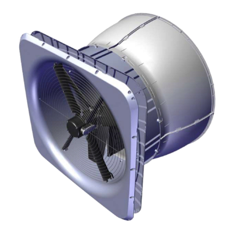
DA 1700 Wall Fan
4.3.29 Seal the inner side ............................................................................................................41
4.3.30 Assembly of cone .............................................................................................................42
4.3.31 Mount the cone on the ventilation duct...........................................................................42
4.3.32 Mounting of inside safety net...........................................................................................43
4.4 Mounting of accessories........................................................................................44
4.4.1 DA 1700 magnet and tool kit ............................................................................................44
4.4.2 Mounting of outside safety net ........................................................................................49
4.4.3 Mounting storm protection on outside safety net ..........................................................50
4.4.4 Mounting storm protection wire for cone........................................................................51
4.4.5 Mounting of outside wall cover........................................................................................52
4.4.6 Mounting outside suspension..........................................................................................53
4.4.7 Mounting of insulation plate.............................................................................................54
5INSTALLATION GUIDE..................................................................................55
5.1 Electrical connection..............................................................................................55
5.1.1 cUL.....................................................................................................................................55
5.1.2 Supply net dimensioning, regarding harmonic distortion .............................................55
5.1.3 Cabling to DA 1700 ...........................................................................................................56
5.1.4 Cabling into the LPC motor controller.............................................................................56
5.2 Connection in the LPC motor controller...............................................................57
5.2.1 Terminals for 230 V power supply ...................................................................................58
5.2.2 Terminals for 400 V power supply ...................................................................................58
5.2.3 Terminals for power supply to fan...................................................................................58
5.2.4 Signal terminals ................................................................................................................59
5.2.5 Terminals on relay module (accessories) .......................................................................59
5.3 LED indication on LPC motor controller...............................................................60
5.4 Alarms......................................................................................................................60
5.5 Emergency opening for DA 1700 shutter motor ..................................................61
5.5.1 Fans active at failure.........................................................................................................61
5.5.2 Fans not active at failure ..................................................................................................62
5.6 Connection to shutter motor .................................................................................63
5.7 Cable plans and circuit diagrams..........................................................................65
5.7.1 General information about circuit diagrams ...................................................................65
5.7.2 Colour code.......................................................................................................................65
5.7.3 Power supply isolator.......................................................................................................65
5.7.4 Letter codes.......................................................................................................................65
5.7.5 Circuit diagrams for OFF/AUTO/ON switch.....................................................................66


