Battipav 90451 User manual

IT MANUALE DI ISTRUZIONE
SRS AVVISATORE DI FASE
GB USER MANUAL
SRS ACOUSTIC PHASE WARNING
art. 90451

Expert 500/600/700

Prime 650/700

4
Battipav srlBattipav srl
1
2
3
4
5
6
7
8

5
Battipav srlBattipav srl
FASE 1
FASE 2
FASE 3
N~0V
N.C. SWITCH
9
10
11
12
13
14
15
16
6
Battipav srlBattipav srl
17
18
19
20
21
22
23
24
7
Battipav srlBattipav srl
25
26
27
28
29

8
IT Battipav srl
“ISTRUZIONI ORIGINALI”
SRS AVVISATORE DI FASE ART.90451
Alimentazione
3 F + N + T 400V 50/60Hz
ATTENZIONE
IL SISTEMA AUTOMATICO DI CORRETTO SENSO
DI ROTAZIONE DELL’UTENSILE è PROGETTATO
UNICAMENTE PER L’UTILIZZO SULLE SEGATRICI
PER EDILIZIA MODELLO BATTIPAV-EXPERT
500/600/700 E PRIME 650/700. IL COSTRUTTORE
DECLINA OGNI RESPONSABILITÀ PER L’USO
DEL SRS AVVISATORE DI FASE IN APPLICAZIONI
DIVERSE DA QUELLE INDICATE.
IMPIEGO
ATTENZIONE
Il componente “SRS AVVISATORE DI FASE” è
un sistema automatico in grado di controllare il
corretto senso di rotazione dell’utensile.
In caso di senso di rotazione invertito, la macchina
non si avvia ed un tono di segnalazione acustica
avvisa la conduzione sbagliata.
IN CASO DI SEGNALAZIONI
ACUSTICHE
11. Scollegare il cavo di alimentazione della
macchina
22. Ruotare con l’aiuto di un cacciavite, due fasi
all’interno della spina della macchina.
33. ATTENDERE 30-60 s PER DAR MODO AL
SISTEMA DI RESETTARSI.
4. Collegare nuovamente il cavo di
alimentazione della macchina.
PRECAUZIONI
ATTENZIONE
• Per evitare false segnalazioni, inserire e
disinserire il cavo di alimentazione più volte
prima di eseguire l’inversione delle fasi.
• Al primo avviamento prima di rendere operativa
la macchina, vericare il corretto funzionamento
del sistema senza utensile, per prendere
dimestichezza con le procedure d’uso.
• Vericate sempre il corretto senso di rotazione
dell’utensile.
INSTALLAZIONE
FARE INSTALLARE L’ACCESSORIO SRS
AVVISATORE SOLAMENTE DA PERSONALE
QUALIFICATO.
PER I MODELLI EXPERT 500/600
Per una corretta installazione dell’ accessorio SRS,
procedere come segue:
4• Rimuovere il carter copridisco.
• Smontare il disco di taglio come indicato nel
manuale di istruzioni allegato alla macchina
(foto 4 del manuale art. 96134).
5 • Slare il tubo acqua dalla valvola di
intercettazione.
6 • Rimuovere la vite di ssaggio tirante
copridisco foto 6 e ruotare quest’ultimo in
modo da liberare la zona di ssaggio della
lamiera di chiusura testa motore foto 7.
8 • Svitarelevitidibloccaggiolamieradichiusura
testa motore e rimuovere la stessa.
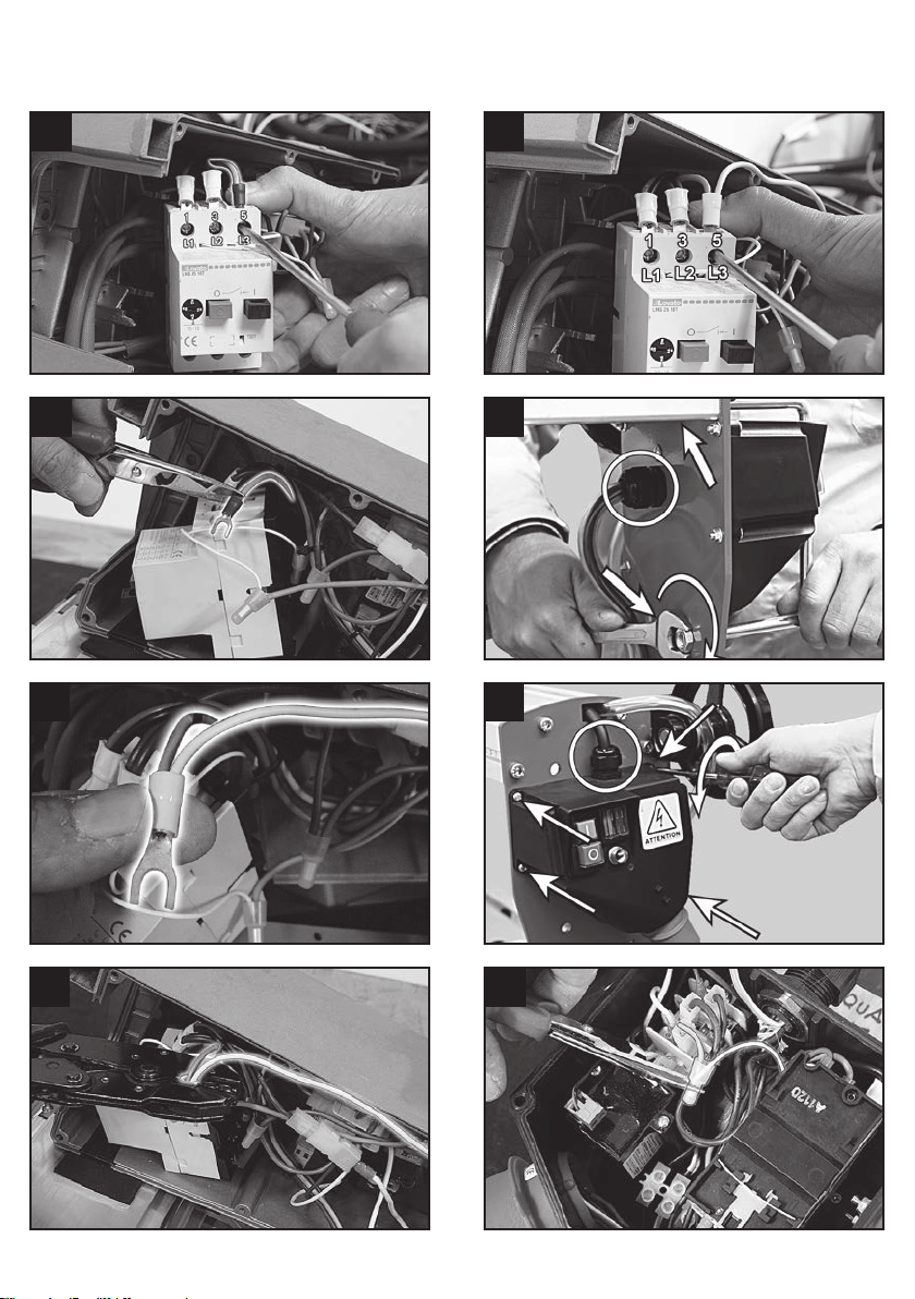
9• Predisporre i terminale in dotazione sui cavi
del SRS con l’aiuto dello schema di foto 9.
9L’ SRS AVVISATORE DI FASE VIENE FORNITO
CON I CAVI DI COLLEGAMENTO PRIVI DI
TERMINALI.
PER MONTAGGIO SU EXPERT 500/600
APPLICARE I TERMINALI FORNITI IN
DOTAZIONE COME DA TABELLA 1 E SCHEMA
DI FIG. 9.
7

9
IT
Battipav srl
TABELLA 1
FASE 1 Spellatura
FASE 2 Faston femmina
Art. 09049
FASE 3 Puntalino preisolato
nero Art. 6002/6
N~0V Spellatura
N.C.SWITCH Spellatura
DOTAZIONE
Art. 09049 x 2 pz.
Art. 96098/1 x 2 pz.
Art. 80040 x 1 pz.
Art. 09050 x 2 pz.
Art. 6002/06 x 1 pz.
10 • Inserire l’ SRS all’interno del vano collegamenti
come da foto 10.
11 • Rimuovere la giunzione che unisce il lo
biancosottile provenientedall’interruttoree il
cavoblucortoprovenientedallamorsettiera.
12 • Unire con giunzione a cappuccio art. 09050
fornita in dotazione il lo bianco appena
tagliato e il cavo N.C.SWITCH del SRS.
Per un corretto serraggio utilizzare una pinza
a cricchetto per terminali.
13 • Unire con giunzione a cappuccio art. 09050
fornitaindotazioneilloblucortoproveniente
dalla morsettiera con cavo N~0V del SRS.
14 • Fissare il CAVO FASE 3 del SRS in morsettiera
in corrispondenza del cavo rosso.
15 • Unire lo marrone corto con faston e cavo
FASE 2 del SRS con giunto art. 80040 fornito
in dotazione.
16 • Estrarre l’interruttore agendo sulla mostrina
frontale come da foto 16.
17 • Allentare vite 5/L3 dell’interruttore ed estrarre
ilcavogrigiodelcablaggio.
18 • Eliminare il terminale a forcella preisolato
rosso.
19 • Unire il cavo grigio appena tagliato con cavo
FASE 1 del SRS su nuovo terminale a forcella
preisolato giallo art. 96098/1 fornito in
dotazione.
20 • Serrare con pinza a cricchetto per terminale.
21 • Fissare il terminale appena serrato su vite 5/
L3 dell’interruttore.
• Riposizionare l’interruttore e i cavi del
cablaggio.
A MONTAGGIO ULTIMATO VERIFICARE IL
CORRETTO FUNZIONAMENTO DEL
COMPONENTE.
ATTENZIONE
ESEGUITE SEMPRE QUESTA PRIMA VERIFICA
SENZA L’UTENSILE DI TAGLIO.
- Collegate la macchina ad una presa di corrente e
vericateilcomportamentodelSRS:
• In caso di segnalazione acustica premere il
bottone di avviamento della macchina per
assicurarsi che non parta.
• In caso di mancata segnalazione premere il
pulsante di avviamento della macchina ed
assicurarsi che si avvii nel senso di rotazione
corretto.
- Spegnere la macchina, estrarre la spina di
alimentazione ed attendere 60 sec.
Ruotare due fasi all’interno della spina della
macchina come foto 2.
- Inserire nuovamente la spina di alimentazione e
vericareilcambiodicomportamentodelSRS.
In caso di avviamento con senso di rotazione
invertito vericare nuovamente tutti i passaggi di
installazione ed eventualmente invertire i cavi fase
2 e 3 del SRS.

10
IT Battipav srl
PER MODELLO PRIME 650/700
Per una corretta installazione dell’accessorio SRS
procedere come segue:
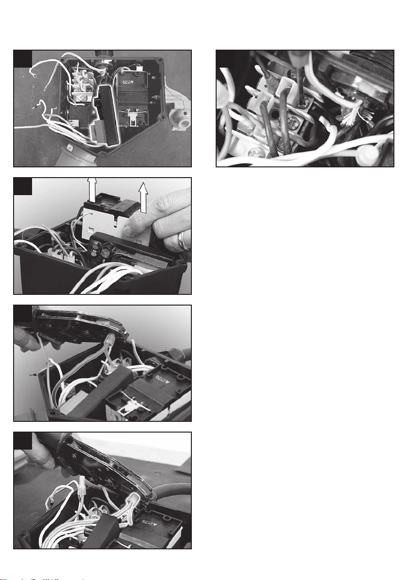
22 • Rimuoverelaprotezionequadrocomandicon
unachiavessada17mm.
22 • Allentare i pressacavi relativi al cavo motore e
al cavo pompa di ricircolo.
23 • Con un giraviti a croce, svitare le viti di
bloccaggioquadrocomando.
24 • All’interno del quadro comandi eliminare
giunzione tra il cavetto BLU corto proveniente
dalla morsettiera e cavetto BIANCO sottile
proveniente dall’interruttore.
25 • Posizionare l’ SRS art. 90451 come indicato in
foto 25.
26 • Estrarrel’interruttoredalquadrocomandi.
• Allentare il morsetto n°3/L2 dell’interruttore ed
estrarre il cavo grigio. Tagliare il terminale a
forcella ed unirlo con CAVO FASE 2 del SRS su
nuovo terminale a forcella fornito in dotazione
art. 96098/1.
• Ripetere l’operazione con cavo marrone in
morsetto n°5/L3 e CAVO FASE 1 del SRS.
• Inserire nuovamente l’interruttore nella sua
posizione.
27 • Unire il cavetto blu del cablaggio interno
proveniente da morsettiera e il cavetto blu
N~0V del SRS con giunzione a cappuccio art.
09050 fornito in dotazione.
27 Per un corretto serraggio utilizzare una pinza
a cricchetto per terminali.
28 • Unireilcavettobiancodell’interruttoreeilcavo
grigio N.C. Switch del SRS con giunzione a
cappuccio art. 09050 Fornito in dotazione.
PER UN CORRETTO SERRAGGIO UTILIZZARE
PINZA A CRICCHETTO PER TERMINALI.
25 • Serrare il cavo FASE 3 del SRS in morsettiera
incorrispondenzadelloN°6provenientedal
motore.
• Posizionare bene tutti i cavi in modo da
contenere l’ SRS entro le quote di ingombro
delquadrocomandi.
22 • Richiudere il quadro eseguendo in senso
inverso le operazioni indicate in foto 22 e 23.
• Vericare il corretto funzionamento del
componente come indicato a pag. 8.
23
23

11
GB
Battipav srl
“ORIGINAL INSTRUCTIONS”
SRS PHASE ADVISOR ART. 90451
Electrical power
3 F + N + T 400V 50/60Hz
CAUTION
THE AUTOMATIC SYSTEM OF THE CORRECT
SENSE OF ROTATION OF THE TOOL IS DESIGNED
ONLY FOR USE ON THE BUILDING SAWS MODEL
BATTIPAV-EXPERT 500/600/700 AND PRIME
650/700. THE MANUFACTURER DECLINES EVERY
RESPONSIBILITY FOR THE USE OF SRS PHASE
ADVISOR IN APPLICATIONS DIFFERENT FROM
THOSE INDICATED.
EMPLOYMENT
CAUTION
The component “SRS PHASE ADVISOR” is an
automatic system able to control the correct
direction of rotation of the tool. In case of an
inverted direction of rotation, the machine does not
start and a loudness of acoustic signal warns about
the wrong conduction.
IN CASE OF ACOUSTIC SIGNALS
11. Disconnect the machine power cable
22. Rotate with the aid of a screwdriver, two
phases inside the machine plug.
33. WAIT 30-60 seconds to let RESET the
SYSTEM
4. Re-connect the power cable of the machine.
PRECAUTIONS
CAUTION
• To avoid false signals, insert and unplug the
power cable several times before doing the
inversion of the phases.
• At the rst start up before making operating the
machine, check the correct system operation
without tools, to become familiar with the
procedures of use.
• Always check the correct sense of the tool
rotation.
INSTALLATION
LET INSTALL THE SRS ADVISOR ONLY BY
QUALIFIED PERSONNEL.
FOR MODELS EXPERT 500/600
For a correct installation of the SRS accessory,
proceed as follows:
4• Remove the disc guard
• Remove the cutting disc as indicated in the
User manual attached to the machine (photo
4 of the manual art. 96134).
5• Remove the water pipe from the valve
interception.
6 • Removethetie-xingscrewofthediskguard
and rotate the latter so to release the xing
zone of the closing metal sheet of the motor
head.
8 • Unscrewthelockingscrewsofthemetalsheet
which close the motor head and remove it.
9 • Preparethesuppliedterminalonthecablesof
the SRS with the help of the scheme in photo
9.
9THE SRS PHASE ADVISOR IS PROVIDED
WITH THE CONNECTING CABLES WITHOUT
TERMINALS. FOR MOUNTING ON EXPERT
500/600 APPLY THE TERMINALS SUPPLIED IN
EQUIPMENT AS FROM TABLE 1 AND DIAGRAM
OF PICTURE 9.
7
12
GB Battipav srl
TABLE 1
FASE 1 SKINNING
FASE 2 FEMALE FASTON
Art. 09049
FASE 3 Black pre-insulated
ferrul Art. 6002/6
N~0V SKINNING
N.C.SWITCH SKINNING
SUPPLIED
Art. 09049 x 2 pz.
Art. 96098/1 x 2 pz.
Art. 80040 x 1 pz.
Art. 09050 x 2 pz.
Art. 6002/06 x 1 pz.
10 • Insert the SRS into the connection
compartment as per photo 10.
11 • Remove the joint that links the white wire
coming from the switch and the blue short
cablecomingfromtheterminalboard.
12 • Combine with cap junction art. 09050
supplied with the white wire just cut and the
N.C. SWITCH cable of the SRS. For correct
tightening use a ratchet plier for terminals.
13 • Combinewithcapjunctionart.09050supplied
with the short blue wire coming from the
terminalboardwithN~0VcableoftheSRS.
14 • Fix the PHASE CABLE 3 of the SRS in the
terminalboardattheredcable.
15 • Join short brown wire with faston and cable
PHASE 2 of the SRS with joint art. 80040
supplied.
16 • Remove the switch acting on the frontal patch
as on picture 16.
17 • Loosen the screw 5/L3 of the switch and
removethegraywiringcable.
18 • Removetheredpre-insulatedforkterminal.
19 • JointhegraycablejustcutwithcablePHASE
1oftheSRSonanewyellowpre-insulatedfork
terminal art. 96098/1 supplied.
20 • Clamp with ratchet pliers for terminal.
21 • Fasten the terminal just tightened to screw 5/
L3 of the switch.
• Get in position again the switch and wiring
cables.
A ULTIMATE ASSEMBLY, CHECK THE CORRECT
FUNCTIONING OF THE COMPONENT.
CAUTION
ALWAYS CARRY OUT THIS FIRST CHECK WITHOUT
THE CUTTING TOOL.
- Connectthemachinetoapowersocketandverify
thebehaviouroftheSRS:
• In case of acoustic signal, press the machine
startbuttontobesureitdoesnotstart.
• In case of missing signal, press the start
buttonofthemachineandmakesureitstarts
in the correct direction of rotation.
- Switch off the machine, remove the plug from
power supply and wait 60 sec. Rotate two phases
insidetheplugofthemachinelikephoto2.
- Insertthepowerplugagainandcheckthechange
inbehaviouroftheSRS.
In case the machine starts with an opposite sense
of rotation, check all the steps of installation again
and eventually, invert the cables phase 2 and 3 of
the SRS.

13
GB
Battipav srl
FOR PRIME 650/700 MODEL
For a correct installation of the SRS accessory,
proceed as follows:
22 • Remove the protection of the control panel
withaxkeyof17mm.
22 • Loosenthecableglandsrelativetothemotor
cableandto thecable ofrecirculationofthe
pump.
23 • Withacrossscrewdriver,unscrewthelocking
screws of the control panel.
24 • Inside the control panel, eliminate the junction
between the short BLUE cable coming from
the control board and the thin WHITE wire
coming from the switch.
25 • Get in position the SRS art. 90451 as indicated
in photo 25.
26 • Pull out the switch from the control panel.
• Loosen the terminal no. 3/L2 of the switch and
extract the gray cable. Cut the terminal fork
and join it with CABLE 2 of the SRS on a new
forkterminalsuppliedart.96098/1.
• Repeat the operation with brown wire in
terminal no. 5/L3 and CABLE PHASE 1 of the
SRS.
• Insert the switch again in its position.
27 • Join the blue cable of the internal wiring
comingfromtheterminalboardandtheblue
cableN~0VoftheSRSwithcapjunctionart.
09050 supplied.
27 For a correct tightening use a ratchet plier for
terminals.
28 • Jointhewhitecableoftheswitchandthegray
cableN.C.switchoftheSRSwithcapjunction
art. 09050 Supplied.
FOR A CORRECT TIGHTENING, USE RATCHET
PLIERS FOR TERMINALS.
25 • TightenthecablePHASE3oftheSRStothe
terminalboardattheN°6wirecomingfrom
the engine.
• Get in position all the cables well in order to
contain the SRS within the volume percentage
of the control panel.
22 • Close the control panel by executing in the
inverted direction the operations indicated in
photos 22 and 23.
• Checkthecorrectoperationofthecomponent
as indicated on page 11.
23

La riproduzione anche parziale e la divulgazione di questo documento, con qualsiasi mezzo, non sono consentite.
Eventuali infrazioni saranno perseguite nei modi e nei tempi previsti dalla legge. Edizione 2016. Con riserva di modiche.
www.battipav.com
Art. 90442DBS
Table of contents
Languages:


