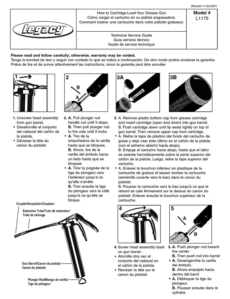
Staubli TX Series User manual

© Stäubli Faverges 2007
Arm - TX series 40 family
Instruction manual
D28065504A - 02/2007

2D28065504A - 02/2007

D28065504A - 02/2007 3
TABLE OF CONTENTS
1 - INTRODUCTION.................................................................................... 7
1.1. FOREWORD ............................................................................................................................. 9
1.1.1. Objective of this manual .............................................................................................. 11
1.1.2. Special messages concerning warnings, alerts, and information................................ 11
1.2. DEFINITION OF THE ELEMENTS AROUND THE ROBOT CELL ........................................ 10
1.3. SAFETY .................................................................................................................................. 11
1.3.1. Reminder concerning the safety standards................................................................. 11
1.3.2. Safety directives concerning to the work environment ................................................ 12
1.3.3. Safety directives concerning to staff protection........................................................... 14
1.3.4. Safety directives concerning to protection of the equipment....................................... 16
2 - DESCRIPTION..................................................................................... 19
2.1. IDENTIFICATION.................................................................................................................... 21
2.2. GENERAL PRESENTATION.................................................................................................. 21
2.3. DESIGNATION OF ROBOTS OF THE TX SERIES 40 FAMILY ............................................ 25
2.4. GENERAL CHARACTERISTICS............................................................................................ 27
2.4.1. Dimensions......................................................................................................................
2.4.2. Work environment ....................................................................................................... 27
2.4.3. Weight ......................................................................................................................... 27
2.5. PERFORMANCE .................................................................................................................... 29
2.5.1. Amplitude, speed and resolution ................................................................................. 29
2.6. LOAD CAPACITY – MECHANICAL INTERFACE ................................................................. 31
2.6.1. Load capacity .............................................................................................................. 33
2.6.2. Torque limits................................................................................................................ 35
2.6.3. Attachment of additional load on forearm.................................................................... 35
2.7. USER CIRCUIT ....................................................................................................................... 39
2.8. PNEUMATIC AND ELECTRIC SYSTEMS ............................................................................. 43
2.8.1. Standard pneumatic system (standard robot equipment) ........................................... 43
2.8.2. Pneumatic system with electric distributor for use with compressed air (option) ........ 47
2.8.3. Pneumatic system with electric distributor for use with vacuum (option) .................... 51
2.8.4. Electric circuit .............................................................................................................. 55

4D28065504A - 02/2007

D28065504A - 02/2007 5
2.9. PRESSURIZATION SYSTEM FOR DUSTY SURROUNDINGS OR SPATTERING WITH
LIQUIDS .................................................................................................................................. 57
2.9.1. Purpose ....................................................................................................................... 57
2.9.2. Installation ................................................................................................................... 57
2.10. RELEASING JOINT BRAKE .................................................................................................. 58
2.11. SAFETY .................................................................................................................................. 58
2.12. JOINT DISPLACEMENT LIMITERS....................................................................................... 59
3 - ON-SITE PREPARATION.................................................................... 61
3.1. WORKING SPACE ................................................................................................................. 65
3.2. ATTACHMENT........................................................................................................................ 65
4 - STORAGE, TRANSPORT AND INSTALLATION ............................... 67
4.1. ARM PACKAGING ................................................................................................................. 68
4.1.1. Conditions of storage and transport ............................................................................ 68
4.2. HANDLING OF PACKING ...................................................................................................... 68
4.3. UNPACKING AND INSTALLATION OF ARM ....................................................................... 68
4.4. INSTALLATION OF ARM ....................................................................................................... 69
4.4.1. Installation of arm ........................................................................................................ 69
4.4.2. Mounting floor quality .................................................................................................. 69
4.4.3. Modification of amplitudes........................................................................................... 69
5 - PREVENTIVE MAINTENANCE ........................................................... 71
5.1. DEFINING THE LEVELS OF INTERVENTION ...................................................................... 73
5.2. PROCEDURE FOR REPLACING THE FLAT SEAL .............................................................. 74
5.3. MAINTENANCE FREQUENCY .............................................................................................. 75
5.4. CHECKING OIL LEVELS ....................................................................................................... 77
5.4.1. Arm in floor-mounted position ..................................................................................... 77
5.4.2. Arm in ceiling-mounted position .................................................................................. 79
6 - RECOMMENDED SPARE PARTS...................................................... 81

6D28065504A - 02/2007

Chapter 1 – Introduction
D28065504A - 02/2007 7
CHAPTER 1 –
INTRODUCTION

8D28065504A - 02/2007

Chapter 1 – Introduction
D28065504A - 02/2007 9
1.1. FOREWORD
The information contained in the present document is the property of STÄUBLI and it cannot be
reproduced, in full or in part, without our prior written approval.
The specifications contained in the present document can be modified without notice. Although all
necessary precautions have been taken to ensure that the information contained in this document is correct,
STÄUBLI cannot be held responsible for any errors or omissions found in the illustrations, drawings and
specifications contained in the said document.
If any difficulties are met with during operation or servicing of the robot that are not referred to in this
document, or if further information is required, please contact the STÄUBLI After Sales Department, "Robot
Division".
STÄUBLI ®, UNIMATION ®, VAL ®
are brands registered by STÄUBLI INTERNATIONAL AG.
1.1.1. OBJECTIVE OF THIS MANUAL
The objective of this manual is to provide information concerning the installation, operation and
maintenance of STÄUBLI robots. It provides help for the persons working on the equipment, for reference
purposes only. Indeed, in order to understand the present document and the use of STÄUBLI robots, it is
necessary for staff to acquire the corresponding knowledge by following a "robots" training course as
provided by STÄUBLI.
The photos are used to make the document easier to understand, they cannot be construed as being of a
contractual nature.
1.1.2. SPECIAL MESSAGES CONCERNING WARNINGS, ALERTS, AND
INFORMATION.
In this document, there are two formats for warnings and alerts. The messages contained in the boxes
inform staff of the potential risks involved in carrying out an action.
These boxes are as follows (they are shown in decreasing order of importance):
Danger message
Warning message
DANGER:
Instructions drawing the reader's attention to the risks of accidents that could
lead to serious bodily harm if the steps shown are not complied with. In general,
this type of indication describes the potential danger, its possible effects and the
steps necessary to reduce the danger. It is essential to comply with the
instructions to ensure personal safety.
CAUTION:
Instructions drawing the reader's attention to the risks of material damage if the steps
shown are not complied with. It is essential to comply with these instructions to ensure
equipment reliability and performance levels.

10 D28065504A - 02/2007
Notes
Paragraphs of the "note" type provide very important information to help the reader to understand a
description or a procedure.
Note:
Supplies further information, or underlines a point or an important procedure. This
information must be memorized to make it easier to apply and ensure correct sequencing
of the operations described.
1.2. DEFINITION OF THE ELEMENTS AROUND THE ROBOT CELL
Person: general term identifying all individuals likely to come close to the STÄUBLI robot cell.
Staff: identifies the persons specifically employed and trained to install, operate, and service the STÄUBLI
robot cell.
User: refers to the persons or the company responsible for operating the STÄUBLI robot cell.
Operator: refers to the person who starts or stops the robot, or controls its operation.

Chapter 1 – Introduction
D28065504A - 02/2007 11
1.3. SAFETY
1.3.1. REMINDER CONCERNING THE SAFETY STANDARDS
The robot is a sub-assembly designed for integration in a robot cell. It has been designed and built to enable
the "robot cell" unit to comply with regulatory provisions. Compliance of the robot cell is the responsibility of
the prime contractor who very frequently is the owner.
"The user must make sure that the staff programming, operating, maintaining or repairing the robot or the
robot cell are correctly trained and show the skills necessary to carry out these tasks in full safety" (extract
from standard NF EN 775).
In France, for example, posters isued by the CRAM are available to remind operators of the safety rules
applicable in the vicinity of robot stations.
The electrical equipment of the robot and the robot cell must comply with standard EN 60204-1.
The characteristics of the power supply and the grounding terminals must comply with the manufacturers'
specifications.
Standards applicable
Installation of the robot must be planned in accordance with the standard instructions.
DANGER:
The robot is a fast moving machine. These movements can be dangerous.
Always comply with the safety standards recommended for robot use and
inform operators about the dangers faced.
• ISO 10218, 1992 International standards
•EEC 98 / 37 "Machine Safety"
Directive
European Directive
•Standard EN 775 Industrial handling robots - Safety
•Standard EN 292 General principles
•Standard EN 294 Safety distances
•Standard EN 418 Emergency stop equipment
•Standard EN 953 Protective elements
•Standard EN 954-1 Machine safety
•Standard EN 349 Minimum clearances
•Standard EN 1050 Risk assessment
•Standard EN 1088 Locking devices
•Standard EN 60204-1 Electrical equipment on machines
•Standard EN 999 Speed on approach towards the human body
•Standard EN 61 000-6-4 Electromagnetic compatibility - Emission
•Standard EN 61 000-6-2 Electromagnetic compatibility - Immunity
•Standard CEI 34-1 Electrical rotating machines
•Standard UL 1740 Robots and Robotics Equipment
•Standard RIA15-06 American National Standard for Industrial Robots and Robot
Systems. Safety Requirements.
•Standard CSA Z434-03 Industrial Robots and Robot Systems. General Safety
Requirements.
•Standard NFPA 79 Electrical standard for industrial machinery
•Standard NFPA 70 National Electrical Code

12 D28065504A - 02/2007
1.3.2. SAFETY DIRECTIVES CONCERNING TO THE WORK ENVIRONMENT
Analysis of safety around the robot cell
Safety must be taken into account for the robot cell from the design and development stage on.
Before planning the installation of the robot cell, it is necessary to study the following points:
•Plan the safety strategies that reduce risks to an acceptable level.
•Define the tasks required for the foreseeable applications and assess the access and/or approach
requirements.
•Identify the sources of risks including the failures and the failure modes associated with each of the tasks.
The risks can involve:
•the cell itself
•its association with other items of equipment
•the interactions between persons and the cell.
•Assess and estimate the risks stemming from cell operation:
•programming risks
•operating risks
•risks during use
•maintenance risks for the robot cell.
•Select the protective methods:
•use of protective devices
•installation of signalling means
•compliance with safe working procedures.
These points are taken from the standards applicable to robots, and especially European standard EN 775.
Note:
This list is not exhaustive. Above all, it is necessary to comply with the standards in force
in your country.
CAUTION:
To ensure reliability and precision in the robot's movements, the robot cell environment
must comply with the levels of disturbance set out in the safety standards.

Chapter 1 – Introduction
D28065504A - 02/2007 13
Rules concerning the robot's work area
The controlled area or isolation area in which the robot moves must be determined using protective devices
(protective elements).
Note:
Protective elements are devices protecting persons from a dangerous area. See the
standards currently in force concerning safety for industrial handling equipment.
DANGER:
At the time of an emergency stop, the final position of the arm can never be
determined precisely because of the kinetic energy involved. It is thus
necessary to make sure that no persons or obstructions are present in the
robot's work area when the arm is powered up.

14 D28065504A - 02/2007
1.3.3. SAFETY DIRECTIVES CONCERNING TO STAFF PROTECTION
STÄUBLI robots work with computer controlled mechanisms, capable of moving at high speed and exerting
considerable force. Like all robots and most industrial equipment, they must be controlled with great care
by the user of the robot cell. All staff using STÄUBLI robots must be familiar with the warnings and
recommendations given in this manual.
Mechanical and electrical dangers.
•Do not connect or disconnect components while the unit is under power. The connection between the
controller and the robot arm can only be made if the controller has been switched off.
•The arm must not be loaded during maintenance operations.
Figure 1.1
DANGER:
Disconnect all the electrical and pneumatic power supplies before carrying out
any work on the controller or the arm.
DANGER:
Each time the arm is powered on, keep one hand close to the "Emergency stop"
button in order to be able to press it as quickly as possible in the event of a
problem.
DANGER:
All persons are prohibited from remaining in the isolation area in which the robot
arm operates. Certain robot working modes such as the "brake release" mode
can lead to unforeseeable arm movements.

Chapter 1 – Introduction
D28065504A - 02/2007 15
Robot cell safety devices
The safety devices must form an integral part of the design and installation of the robot cell. Operator
training and compliance with the operating procedures constitute a major element in setting up the safety
devices and systems.
STÄUBLI robots are equipped with various communication functions, helping the user to develop safety
devices for the robot cell. These functions include emergency stops and digital Input/Output lines.

16 D28065504A - 02/2007
1.3.4. SAFETY DIRECTIVES CONCERNING TO PROTECTION OF THE
EQUIPMENT
1.3.4.1. CONNECTIONS
•Before connecting the controller to the power supply, make sure that its nominal voltage does indeed
correspond to the network voltage.
•When connecting the controller, use a cable whose cross-section corresponds to the power rating shown
on the manufacturer's plate.
•Before removing or inserting an electronic component, switch off arm power and then switch off controller
power and comply with the procedure.
•Take care to avoid blocking the air inlets and outlets for the controller airflow path.
•Never use the emergency stop to power down the arm under normal conditions of use.
1.3.4.2. INFORMATION ON ELECTROSTATIC DISCHARGES
What is an electrostatic discharge?
Everyone has felt the effects of static electricity on their clothes or when they touch a metal object, without
being aware of the damage that can be done to electronic components by static electricity.
Our desire to integrate the notions of quality and reliability in our products makes it necessary to prevent
electrostatic discharges from causing damage to them. This means that all the staff and login users must
be informed.
Storage of a charge
An electric charge is created simply by combining a conductor, a dielectric and the ground (lowest reference
potential, usually the ground in the case of an electrostatic charge).
Example: people, printed circuits, integrated circuits, components, conducting mats when separated from
the ground by a dielectric.
Electrostatic discharges or ESD
Most people have experienced ESD by receiving an electric shock when walking on a carpet and touching
a doorknob or when getting out of a car.
In most case, the following is true:
•To feel an ESD, a charge of at least 3500 V is required.
•To hear one, a charge of at least 5000 V is required.
•To see a spark, a charge of at least 10 000 V is required.
This shows that it is possible to develop charges of over 10 000 V before noticing an electrostatic discharge!

Chapter 1 – Introduction
D28065504A - 02/2007 17
Risks created by an electrostatic discharge
A high ESD voltage (several thousand volts) creates danger for electronic components. A semi-conductor
must be handled carefully to prevent destruction by ESD. ESD are truly dangerous. It is estimated that they
destroy only 10% of the components that they effect. The other 90% of components fall into the
"deteriorated" category. A component may be damaged with simply 25% of the voltage required to destroy
it.
These hidden faults can lead to problems that appear several days, weeks or even months after the
incident. Components may also undergo a change in their operating characteristics. Initial tests are
successfully passed but an intermittent error occurs under vibration or temperature constraints. The same
components will pass the "on/off" test successfully, as carried out during repairs, but the problem will
reappear again once on site.
Typical ESD voltages
Source
Low relative
humidity
10 - 20%
Average relative
humidity
40%
High relative
humidity
65 - 90%
Walking on carpet 35 kV 15 kV 1,5 kV
Walking on vinyl 12 kV 5 kV 0,3 kV
Working at the
workstation
6 kV 2,5 kV 0,1 kV
Plastified instructions 7 kV 2,6 kV 0,6 kV
Polyethylene bags 20 kV 2 kV 1,2 kV
Cellular polyurethane 18 kV 11 kV 1,5 kV
Charge sources
Work surfaces Packaging
Floors Handling
Chairs Assembly
Carriages Cleaning
Clothes Repairing
Parts sensitive to static charges
Electronic cards
Power supplies
Encoders
etc

18 D28065504A - 02/2007
1.3.4.3. PREVENTION OF DAMAGE DUE TO ELECTROSTATIC DISCHARGES
It is essential to guard against electrostatic discharges during an intervention concerning electronic
components, sub-assemblies and complete systems.
Elimination of the danger due to ESD requires a combined team effort. By complying with the following
instructions, you can substantially reduce the potential damage caused by ESD and ensure long-term
reliability for the robot.
•Inform the staff of the risks stemming from ESD.
•Know the critical zones sensitive to ESD.
•Know the rules and procedures to deal with ESD.
•Always carry components and boards in a tray to protect them from electrostatic charges.
•Always ground yourself before working on a workstation.
•Keep non-conducting equipment (static charge generators) away from components and boards.
•Use tools providing protection from ESD.
STÄUBLI workstation
To handle electronic cards, STÄUBLI workstations are given a grounded coating that dissipates static
electricity. An anti-static bracelet is required to handle boards or electronic components.
Work zones
Remove objects that generate static electricity charges from the work area, such as:
•plastic cups
•polystyrene
•notebooks
•plastic files and document holders.
Printed circuits, boards and electronic components must be kept in anti-static bags.
Anti-static wrist strap
Use an electrostatic wrist strap connected to the frame of the controller or to the frame of the arm and the
ground during all handling of boards or components. The wrist straps are supplied as part of the standard
equipment for the robot.
CAUTION:
Use an electrostatic wrist strap and an electrostatic mat connected to the controller
during all handling of boards or components.

Chapter 2 – Description
D28065504A - 02/2007 19
CHAPTER 2 –
DESCRIPTION

20 D28065504A - 02/2007
Figure 2.1
1
2
A
5
4
3
C
E
F
6
B
D
Table of contents
Other Staubli Tools manuals
Staubli
Staubli 16BL-MP Series User manual
Staubli
Staubli MA270 User manual
Staubli
Staubli MA289 User manual
Staubli
Staubli PV-MS-PLS/1 User manual
Staubli
Staubli PV-KST4 UR Series User manual
Staubli
Staubli PV-AZM Series User manual

Staubli
Staubli PV-AZM Series User manual

Staubli
Staubli PV-AZM User manual
Staubli
Staubli GSRD Series User manual

Staubli
Staubli PV-AZM Series User manual
Popular Tools manuals by other brands
BGS technic
BGS technic 6932 instruction manual

Atlas Copco
Atlas Copco ETP SRB81-1300-20-HA-D Product instructions
Macnaught
Macnaught MAN1915-01 manual

ISANTA
ISANTA SENCO DS220 operating instructions

Johnson Controls
Johnson Controls MS-FIT100-0 user guide

TECNOPLUS
TECNOPLUS SYSTEM-AIR 7041.61 instruction manual
