Bauer Jupiter 250 User manual

2
Allgemeine Angaben
Sicherheitshinweise
-Die Montageanleitung muss beachtet werden.
-Bei Nichtbeachtung der Montageanleitung wird eine Haftung des Herstellers aus-
geschlossen.
-Nehmen Sie kein beschädigtes Tor oder beschädigten Torantrieb in Betrieb!
-Die gültigen Richtlinien müssen beachtet werden, z.B. EN 12453, EN 12604, EN
12605.
-Die Benutzer müssen in die Funktionen der Anlage eingewiesen werden.
-Arbeiten an der Anlage dürfen nur im spannungsfreien Zustand durchgeführt
werden.
-Nur Originalersatzteile und Originalzubehör verwenden!
General remarks
Safety instructions
- The mounting instructions must be adhered to.
- The manufacturer assumes no liability for any damages resulting from
the non- adherence to these mounting instructions.
- Do not commission any defect gate or gate operator.
- The relevant directives must be adhered to e.g. EN 12453, EN 12604
and EN 12605.
- The users must be initiated in the individual operations of the device.
- Any work relating to the device can only be done when there is no supply voltage.
- Use only original spare and component parts.
Remarques générales
Consignes de sécurité
- La notice de montage doit être respectée.
- Le fabricant décline toute responsabilité si la notice de montage n’est pas respectée.
- Ne mettez pas de portails ou d’opérateurs défectueux en service.
- Les directives valables comme p.ex. EN 12453, EN 12604, EN 12605 doivent être
respectées.
- Les clients doivent être initiés aux fonctionnements du système.
- Ne travaillez qu’à l’opérateur si celui-ci est hors de tension.
- N’utilisez que des pièces de rechange originales ainsi que des accessoires
originaux.

Inhaltsverzeichnis
2) Technische Daten......................................................................................................................... 4
3) Wirkungsweise............................................................................................................................. 5
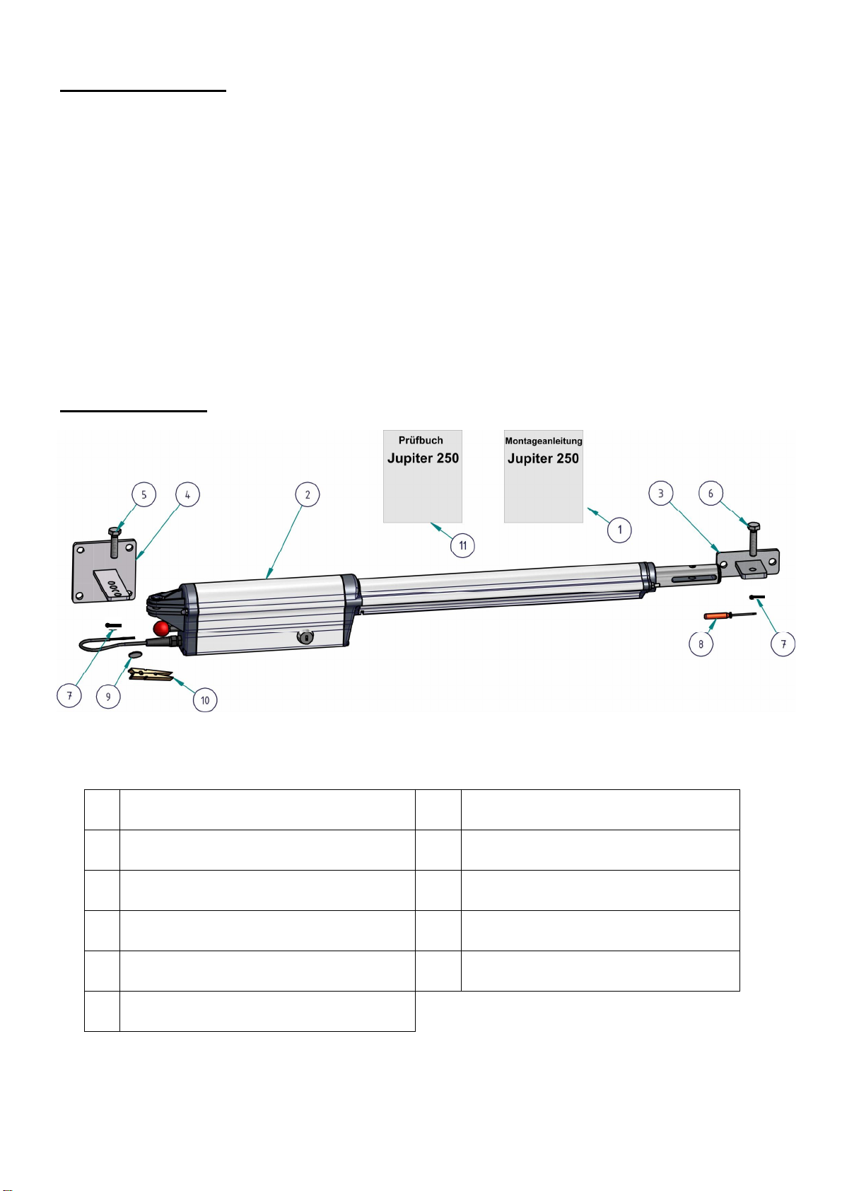
4) Lieferumfang................................................................................................................................ 5
5) Abmessungen/Montagemaße........................................................................................................ 6
6) Montage des Antriebes................................................................................................................. 7
7) Einstellen der Endschalter ............................................................................................................ 8
7.1) Einstellen des Endschalters „ZU“................................................................................................. 8
7.2) Verschieben der Endschalter......................................................................................................... 9
7.3) Einstellen des Endschalters „AUF“............................................................................................... 9
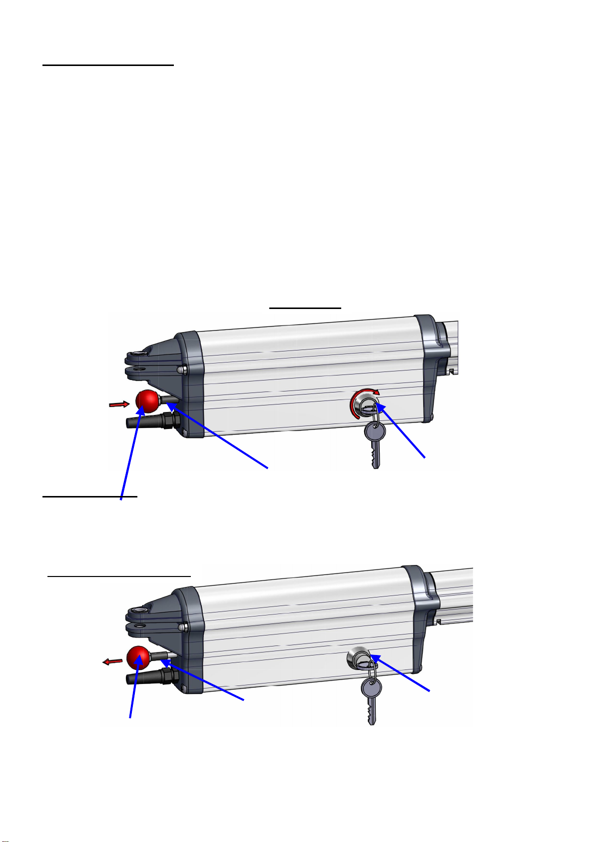
8.) Notentriegelung.......................................................................................................................... 10
8.1) Verriegeln des Antriebes ............................................................................................................ 11
9) Kabelplan................................................................................................................................... 11
10) Wartung der Toranlage............................................................................................................... 12
11) Elektrischer Anschluss ............................................................................................................... 12
12) Konformitätserklärung............................................................................................................13/14
Table of contents:
13) Mode of operation...................................................................................................................... 15
14) Scope of delivery........................................................................................................................ 15
15) Dimensions/mounting dimensions.............................................................................................. 16
16) Mounting of the operator............................................................................................................ 17
17) Adjustment of end switches........................................................................................................ 18
17.1) Adjustment of end switch “CLOSED”........................................................................................ 18
17.2) Altering the position of end switches.......................................................................................... 19
17.3) Adjustment of end switch “OPEN”............................................................................................ 19
18) Emergency release...................................................................................................................... 20
18.1) Locking the operator.................................................................................................................. 21
19) Cable layout ............................................................................................................................... 22
20) Maintenance............................................................................................................................... 23
21) Electrical connection .................................................................................................................. 23
22) Declaration of conformity ......................................................................................................24/25
Inhaltsverzeichnis
23) Mode opératoire ......................................................................................................................... 26
24) Contenu de la livraison............................................................................................................... 26
25) Dimensions/dimensions de montage........................................................................................... 27
26) Montage de l’opérateur............................................................................................................... 28
27) Ajustage des commutateurs de fins de course ............................................................................. 29
27.1) Ajustage du commutateur de fin de course « FERME ».............................................................. 29
17.1) Changer la position des commutateurs de fin de course .............................................................. 30
27.3) Ajustage du commutateur de fin de course « OUVERT » ........................................................... 30
28.) Déverrouillage d’urgence ........................................................................................................... 31
28.1) Verrouiller l’opérateur................................................................................................................ 32
29) Plan de câblage........................................................................................................................... 33
30) Maintenance............................................................................................................................... 34
31) Connexion électrique.................................................................................................................. 34
32) Déclaration de conformité CE.................................................................................................35/36

4
2. Technische Daten 2. technical data 2. données techniques
Netzanschluss mains supply alimentation
sur secteur 230V / 50 –60 Hz
Motorspannung / Strom motor voltage/
current tension de mo-
teur 12V DC 5A
Motorbremse engine brake frein moteur 12V DC 1,5 A
Leistung engine output puissance du
moteur 118 W
Öffnungszeit bei 900C Opening time
at 900C Temps de
l’ouverture à
900C
Typisch. 15 sek
Typical 15 sec.
Typiquement 15 sec.
Arbeitshub max. maximum po-
wer stroke course de tra-
vail maximu-
me
330 mm
Max. Kraft Maximum
force Force maxima-
le 2000 N
Temperaturbereich temperature
range gamme de
température -200C bis +500C
from 200C to + 500C
de 200C à + 500C
max. Bewegungsfreq. maximum mo-
vement fre-
quency
fréquence de
mouvement
maximale
20 x Stunde
20 x per hour
20 x par heure
max. Flügellänge maximum wing
length Longueur ma-
ximale du van-
tail
2,5 m
max. Torgewicht maximum gate
weight Poids maximal
du portail 200 kg

5
3. Wirkungsweise
Der Antrieb arbeitet elektromechanisch. Ein 12 V Gleichstrommotor treibt eine Spindel
an. Über eine fest mit der Spindelmutter verbundene Schubstange wird die Spindel aus
dem Antriebskörper heraus- oder hineingeschoben und dadurch das Tor bewegt.
Bei Erreichen der eingestellten Endlagen schaltet der Antrieb automatisch über Endschal-
ter ab.
Bei Torflügeln über 2 m oder 2-flügeligen Toranlagen empfiehlt es sich, einen Toran-
schlag in „TOR ZU“-Stellung anzubringen. Als zusätzliche Verriegelung kann ein Elekt-
roschloss eingebaut werden.
Der Antrieb ist selbsthemmend. Das Tor kann im verriegelten Zustand (Normalbetrieb)
von Hand nicht aufgeschoben werden, ohne dass der Antrieb oder die Beschläge beschä-
digt werden. Sollte die Selbsthemmung des Antriebes nicht ausreichen, so muss ein zu-
sätzliches Elektroschloss eingebaut werden.
4. Lieferumfang
(1) 1St. Montageanleitung (7) 2St. Splinte 3,2 x 20
(2) 1St. Antrieb Jupiter 250 (8) 1St. Schraubendreher klein
(3) 1St. Beschlag für Torpflügel (9) 1St. Knopfzelle 3V
(4) 1St. Beschlag für Pfeiler/Pfosten (10) 1St. Klammer
(5) 1St. Splintbolzen 10 x 36 (11) 1St. Prüfbuch
(6) 1St. Splintbolzen 10 x 36

6
5. Abmessungen / Montagemaße
Beim Einbau des Antriebes müssen die Montagemaße (Maße in mm) eingehalten werden
A
B
90
C
100
C
110
C
120
C
13
0
C
140
C
100 1070
1110 1020
1110 980
1115 940
1115 920
1120 900
1130
120 1100
1120 1070
1125 1030
1130 990
1135 970
113,5 950
1140
140 1130
1130 1100
1135 1080
1140 1050
1145 1030
115,0 1000
1155
160 1170
1150 1130
1155 1090
1160 1050
1160 1010
1165 970
1165
180 1200
1165 1110
1165 1060
1170 1000
1170 970
1170 940
1175

7
6. Montage des Antriebes
Hinweis: Der Anbau des Antriebes ist denkbar einfach. Vor Beginn der Montage
sollte jedoch die Montageanleitung sorgfältig gelesen werden. Einbaufehler können
dadurch vermieden, Zeit und Ärger erspart werden. Für die Beschädigung des An-
triebes durch fehlerhafte Montage kann der Hersteller keine Gewährleistung über-
nehmen.
Für die einwandfreie Funktion des Antriebes ist ein leichtgängiges Tor ohne Stütz-
räder Bedingung. Die Angeln sollten spielfrei sein. Für Tore mit großer Windlast ist
dieser Antrieb nicht geeignet.
Signalleitungen dürfen eine Länge von 30m nicht überschreiten. Ab einer Kabellän-
ge von 5m ist ein abgeschirmtes Kabel zu verwenden.
Messen Sie entsprechend dem Pfosten/Pfeiler das Maß A und
B (siehe Seite 6 Punkt 5, „Abmessungen / Montagemaße“) aus
und befestigen Sie den Pfosten-/Pfeilerbeschlag an dem Tor-
pfosten/-pfeiler.
(Die Pfosten-/Pfeilerbeschläge können angeschweißt oder
angeschraubt werden. Wird der Pfosten-/Pfeilerbeschlag ange-
schraubt, so sind Dübel zu wählen, welche sich im Betrieb
nicht lockern können. Am besten eignen sich Klebe-
Verbundanker.)
Der Abstand vom Boden bis zur Unterkante des Pfosten-
/Pfeilerbeschlages muss mindestens 100 mm betragen.
Drehen Sie die Schubstange solange heraus, bis das Maß C (siehe Seite 6 Punkt 5,
„Abmessungen / Montagemaße“) erreicht ist. Kontrollieren Sie die waagrechte Aus-
richtung des Antriebes.
Nun befestigen Sie den Torflügelbeschlag an dem geschlossenen Tor.

8
7. Einstellen der Endschalter
Lösen Sie den Antrieb von dem Pfosten-/Pfeilerbeschlag und dem Torflügelbeschlag
und befestigen den Antrieb mit der Unterseite nach „Oben“ wieder an dem Pfosten-
/Pfeilerbeschlag und dem Torflügelbeschlag. Somit wird die Einstellung der End-
schalter erleichtert.
7.1 Einstellen des Endschalters „ZU“
Klemmen Sie die Anschlussleitung des Antriebes mit der Klammer an die mitgelie-
ferte 3V Knopfzelle, so dass die Leuchtdiode des Endschalters „ZU“leuchtet.
Lösen Sie nun die Feststellschraube (siehe Seite 9 Punkt 7.2 „Verschieben der End-
schalter“) des Endschalters „ZU“und verschieben diesen so lange in Richtung Mo-
torgehäuse, bis die Leuchtdiode des Endschalters „ZU“erlischt. Jetzt hat der End-
schalter „ZU“die richtige Position.

9
7.2 Verschieben der Endschalter:
Mit dem mitgelieferten Schraubendreher können Sie das Endschalterkabel aus dem
Führungsprofil herausheben. Nach dem Lösen der Feststellschraube des Endschal-
ters kann dieser durch Schieben oder Ziehen an dem Endschalterkabel verstellt wer-
den. Ist der Endschalter richtig eingestellt, so muss dieser durch die Feststellschrau-
be wieder befestigt werden. Das restliche Endschalterkabel wird in das Motorgehäu-
se eingeschoben.
7.3 Einstellen des Endschalters „AUF“
Entriegeln Sie den Antrieb mit Hilfe der Notentriegelung (siehe Seite 10 Punkt 8
„Notentriegelung“) und schieben das Tor in die gewünschte Stellung „AUF“. Wech-
seln Sie nun die Anschlussdrähte an der 3 V Knopfzelle, so dass die Leuchtdiode
des Endschalters „AUF“leuchtet. Lösen Sie nun die Feststellschraube des Endschal-
ters „AUF“und verschieben diesen so lange in Richtung „Schubstange-Ende“, bis
die Leuchtdiode des Endschalters „AUF“erlischt. Jetzt hat der Endschalter „AUF“
die richtige Position.

10
Entriegelungsknopf
(nach hinten gezogen)
Gummitülle Schloss
(Innenteil herausgesprungen)
Entriegelungsknopf
Gummitülle
Schloss
8. Notentriegelung
(Notentriegelung nur im stromlosen Zustand durchführen!)
Bei Stromausfall kann das Tor von Hand geöffnet oder geschlossen werden, unab-
hängig davon in welcher Stellung es sich gerade befindet.
Um den Antrieb notzuentriegeln drehen Sie den Schlüssel 450 nach rechts. Das In-
nenteil des Schlosses muss ca. 1,5 cm nach Außen springen. Wenn das Innenteil des
Schlosses nicht nach Außen springt, müssen Sie den Entriegelungsknopf in Rich-
tung „Motorgehäuse“drücken und das Innenteil des Schlosses mit Hilfe des Schlüs-
sels nach Außen ziehen. (Dadurch entriegelt sich das Motorhalteblech und der Mo-
tor wird von der Schubspindel getrennt. Der Enriegelungsknopf muss sich deutlich
nach hinten bewegen.)
Der Torflügel kann von Hand bewegt werden.
Entriegeln
Entriegelter Zustand

11
8.1 Verriegeln des Antriebes:
Schieben Sie den Enriegelungsknopf in Richtung „Motorgehäuse“, bis das Innenteil
des Schlosses in die Halterung des Motorbleches eingeschoben werden kann.
Die richtige Stellung der Verriegelung erkennen Sie daran, dass die Gummitülle
leicht gestaucht ist. Jetzt kann der Schlüssel wieder abgezogen werden.
Das Tor lässt sich nun wieder automatisch betreiben.
9. Kabelplan
An dem Antrieb ist bereits ein Versorgungskabel (12V) von 100cm Länge installiert.
Die Anschlüsse der Endschalter sind in dem Motorgehäuse verschaltet und müssen
nicht nach Außen geführt werden.
Die Motorleitung von der Steuerung zum Motorkabel muss bei einer Länge bis 4m
mit einem Querschnitt von 2x1,5mm2und bei einer Länge über 4m mit einem Quer-
schnitt von 2x2,5 mm2verlegt werden.
Verriegeln
Entriegelungsknopf
Gummitülle
Schloss
Zuleitung
230V (3x1,5)
Lichtschranke
(4x0,8
)
Motorleitung
12V (2x1,5) bis 4m Länge
12V (2x2,5) ab 4m Länge

12
10. Wartung der Toranlage
Kraftbetätigte Toranlagen müssen vor der ersten Inbetriebnahme und mindestens
einmal jährlich einer fachgerechten Sicherheitsprüfung/-wartung durch einen Sach-
kundigen unterzogen werden. Die Durchführung der Prüfung und deren Ergebnisse
sind im mitgelieferten Prüfbuch festzuhalten.
Die Schubstange sollte unabhängig von der Sicherheitsprüfung/-wartung einmal im
Jahr von außen mit einem sauberen Tuch gereinigt und mit Silikonspray leicht ein-
gesprüht werden.
11. Elektrischer Anschluss
Hierzu verwenden Sie die Montageanleitung „Motorsteuerung 47-31-250“.

13
12. EG –Konformitätserklärung
BelFox Torautomatik
Produktions- u. Vertriebs GmbH
Gewerbestrasse 3+5
D –36148 Kalbach
Wir erklären hiermit, dass die nachstehend aufgeführten Geräte allen einschlägigen zutreffenden
EG-Richtlinien und Normen entsprechen:
1999/5/EG R&TTE –Richtlinie, R&TTE - directive
Gerätebezeichnung:
Drehtorantrieb Jupiter - 250
Angewandte Richtlinien und Normen sind unter anderem:
EG-Bauproduktenrichtlinie ( 89/106/EG)
EG-Maschinenrichtlinie (98/37/EG)
Niederspannungsrichtlinie (73/23/EG)
EMV-Richtlinie (89/336/EEC)
Niederspannungsrichtlinie (73/23/EEG)
Nutzungssicherheit kraftbetätigter Tore, Anforderungen (EN 12453)
Nutzungssicherheit kraftbetätigter Tore, Prüfverfahren (EN 12445)
Die Übereinstimmung wurde nachgewiesen durch:
Technischer Bericht „funktionale Sicherheit“, insbesondere EN 60335-1,
TÜV Süddeutschland
Dudenstr. 28
D-68167 Mannheim
Erstprüfung nach DIN EN 13241-1
RWTÜV Systems GmbH
Langemarckstr. 20
D-45141 Essen
Ort: D-36148 Kalbach Datum: 03.03.2010
Unterschrift des gesetzlich Haftenden: ________________________
Name und Funktion: Edgar Fierle, Geschäftsführer

14
Seite 2 zur EG-Konformitätserklärung Drehtorantrieb Jupiter-250
Aufgrund der auf Seite 1 aufgeführten Normen und dem Nachweis der Übereinstimmung des ge-
prüften Antriebes mit diesen Normen sowie dem Prüfbericht von RWTÜV Systems vom 03.03.2010
ist der Betrieb des Antriebes Jupiter-250 wie folgt zulässig:
Betrieb bis 200 Kilogramm Torgewicht und 2,5 Meter Torbreite ohne Sicherheitskontaktleiste.
Ausdrücklich wird darauf hingewiesen, dass weitere Sicherheitseinrichtungen wie beispielsweise
Lichtschranken zur Ausrüstung eines kraftbetätigten Tores notwendig sein können.

15
Mounting instructions- mechanics
13. Mode of operation
The device is operated electromechanically. A 12 V DC motor drives a shaft. A driving
rod attached to the screw nut pushes the shaft out of or into the drive unit thus moving the
gate. As soon as the operator reaches the end positions which have been set before it
automatically stops by means of the end switches.
When the wings of the gate exceed 2 m or a gate is provided with two wings it is recom-
mendable to mount a stopper in the position “GATE CLOSED”. To have an additional
locking device, you can install an electronic lock.
The operator is self-locking. When the gate is locked (normal operation), it is not possible
to open it manually without doing damage to the operator or the sheathing. If the self-
locking capacity of the gate is insufficient, you have to install an electronic lock in addi-
tion.
14. Scope of delivery
(1) 1 x mounting instructions (7) 2 x cotter-pin 3,2 x 20
(2) 1 x operator Jupiter 250 (8) 1 screwdriver small
(3) 1 x sheathing for gate wing (9) 1 button cell 3 V
(4) 1 x sheathing for pile (10) 1 x clamp
(5) 1 x hexagon bolt M10x40 (11) 1 x silicone aerosol
(6) 1 x hexagon bolt M10x45

16
15. dimensions / mounting dimensions
When mounting the operator you have to stick to the mounting dimensions (in mm).
A
B
90
C
100
C
110
C
120
C
130
C
1
40
C
100 1070
1110 1020
1110 980
1115 940
1115 920
1120 900
1130
120 1100
1120 1070
1125 1030
1130 990
1135 970
113,5 950
1140
140 1130
1130 1100
1135 1080
1140 1050
1145 1030
115,0 1000
1155
160 1170
1150 1130
1155 1090
1160 1050
1160 1010
1165 970
1165
180 1200
1165 1110
1165 1060
1170 1000
1170 970
1170 940
1175

17
16. Mounting of the operator
Note: The mounting of the operator is absolutely easy. Nevertheless you should
carefully read the mounting instructions before starting the mounting. This prevents
you from making any mistake and allows you to save time and to avoid trouble. The
manufacturer cannot assume any liability for any damage of the operator which re-
sults from an incorrect mounting.
In order to make sure that the operator works without any difficulty a smooth-
running gate without stabilizers is required. The hinges should be free of clearance.
This operator is not appropriate for gates exposed to a heavy wind load.
Signalling lines may not exceed the length of 30 m. As soon as the length of the ca-
ble exceeds 5 m you have to use a shielded cable.
Measure the dimension A and B (see page 16) according to the
pile and fix the sheathing of the pile to the pile itself.
(The sheathings can be welded or screwed. If the sheathing is
screwed, you have to choose anchor bolts which do not loosen
when the operator is active. The best solutions are adhesive
shear connectors).
The distance from the floor to the bottom edge of the sheathing
of the pile has to amount to at least 100 mm.
Now fix the sheathing of the gate wing to the closed gate in such a way that the di-
mension C (see page 16, point 15 “dimensions/mounting dimensions“) is not ne-
glected. In order to do so turn the driving rod as long as the dimension C is reached.
Check the horizontal alignment of the operator.

18
17. Adjustment of end switches
Remove the operator from the sheathing of the pile and the sheathing of the gate
wing and fix it once again with the rear side pointing to “the top “. This makes it
easier to adjust the end switches.
17.1 Adjustment of end switch “CLOSED “
Using the clamp attach the connecting cable to the 3 V button cell included in the
delivery. This makes the LED of the end switch “CLOSED “flash.
button cell crankcase end switch “OPEN”
clamp end switch “CLOSED “
Now remove the locking screw of the end switch “CLOSED “(see page 19 , point
17.2 “Altering the position of end switches”) and move it towards the crankcase un-
til the LED of the end switch “CLOSED”ceases to flash. Now the end switch
“CLOSED”has reached the correct position.
end switch “OPEN” end switch “CLOSED “

19
Legend:
Feststellschraube : locking screw
Schraubendreher : screw driver
Endschalter: end switch
17.2 Altering the position of end switches:
Using the screw driver included in the delivery you can remove the end switch ca-
bles from the guiding profile. After having released the locking screw of the end
switch, you can alter its position by moving or pulling the cable of the end switch.
When the end switch has reached the correct position, you have to fix it again using
the locking screw. The remaining cable of the end switch is introduced into the
crankcase.
cable of the end switch
screw driver end switch
17.3 Adjustment of end switch “OPEN “
Unlock the operator using the emergency release (see page 20, point 18 “emergency
release “) and move the gate until it reaches the desired position “OPEN “. Now ex-
change the connecting wires at the 3V button cell so that the LED of the end switch
“OPEN”will start to flash. Release the locking screw of the end switch “OPEN”
and move it towards “the end of the driving rod “until the LED of the end switch
“OPEN”ceases to flash. Now the end switch “OPEN”has reached the correct posi-
tion.

20
release button
(pulled backwards)
grommet lock
(inner part outwards)
release button
grommet lock
18. Emergency release
(Only make an emergency release when the operator is disconnected from the
mains)!
When there is a mains failure, you can open and close the gate manually regardless
of the position the gate has got at present time.
In order to make an emergency release, turn the key 45° to the right. The inner part
of the lock must jump about 1.5 cm outwards. If it doesn’t do so, you have to push
the release button towards “the crankcase”. Moreover you have to pull the inner part
of the lock outwards using the key. (Thus the retaining plate of the engine is released
and the engine is separated from the shaft. The release button must move backwards
considerably).
The gate wing can be moved manually.
How to release the operator
Operator in released
state
Table of contents
Languages:
Other Bauer Gate Opener manuals