Baum 714XLT Manual

Set up instructions for the 714XLT
· Theory of buckle folding
· Setting up a Job
· Appendix A – Squaring the feeder side guides
· Appendix B – Installing perforators
· Appendix C – Installing / removing score blades
· Parts Order form
Before working on the folder, DISCONNECT ALL ELECTRICAL POWER SUPPLY TO
THE FOLDER to prevent the accidental start of the folder. Check to be sure you have the
correct tools to complete the job.
For reasons of safety, long hair must be tied back or otherwise secured, garments
must be close fitting and no jewelry, such as rings or necklaces, may be worn while
adjusting or setting up equipment. Injury may result from being caught up in the
machinery or jewelry catching in moving parts. Take all necessary steps so this
doesn’t happen.
For more information or to order parts phone Baum at 1-800-543-6107
Baumfolder Corporation
P.O. Box 728 1660 Campbell Rd
Sidney, Ohio, U.S.A. 45365
Phone : 1-800-543-6107 or 1-937-492-1281
Fax: 1-937-492-7280
Copyright ã2002

Set up instructions for the 714XLT
Baumfolder Corporation P.O. Box 728 1660 Campbell Rd, Sidney, Ohio USA 45365 Copyright © 2002
Phone 1-800-543-6107 or 1-937-492-1281 Fax 1-937-492-7280 email: Baumfolder@baumfolder.com
If a sheet of paper is laid on a flat surface and driven into a stationary object, a buckle or a series of
buckles will form along the surface of the sheet.
If the paper is pushed into a narrow channel before butting up against the stationary object, the buckle
that forms in the channel will be a much smaller size than free-forming buckles. At the end of the
channel, however, larger buckles will again start to form.
If the channel is angled to produce a down-ward pressure, and two folding rollers, spinning as indicated
above, are placed close to the end of the channel, the larger buckles that start forming there will always
form down-ward and be pulled into the rollers, compressing into a fold.
On a buckle folder (like the 714), the sheet comes out of the
feeder flat and enters the fold plate assembly where it comes to a
stop against a stationary fold stop. A series of buckles then forms
through the sheet. The buckles within the fold plate are kept very
small by the narrow channel design. The buckle at the end of the
plate, however, will be larger. The fold plate and rollers are
configured such that the large buckle will always form downward
where it is grabbed by the fold rollers and compressed into a fold.
The picture shows the second plate deflected. This would mean a
single fold.

Set up instructions for the 714XLT
Baumfolder Corporation P.O. Box 728 1660 Campbell Rd, Sidney, Ohio USA 45365 Copyright © 2002
Phone 1-800-543-6107 or 1-937-492-1281 Fax 1-937-492-7280 email: Baumfolder@baumfolder.com
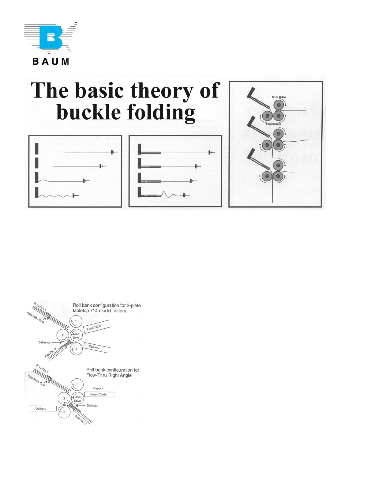
Time to set up a job…..
We are now ready to set up a job on the folder. Ask your customer for a sample of the job he/she wants
to run. This will give you, the sheet size and type fold. Let’s take for example an 8 ½ “ x 11” letter fold.
The example shown is with the header folded in.
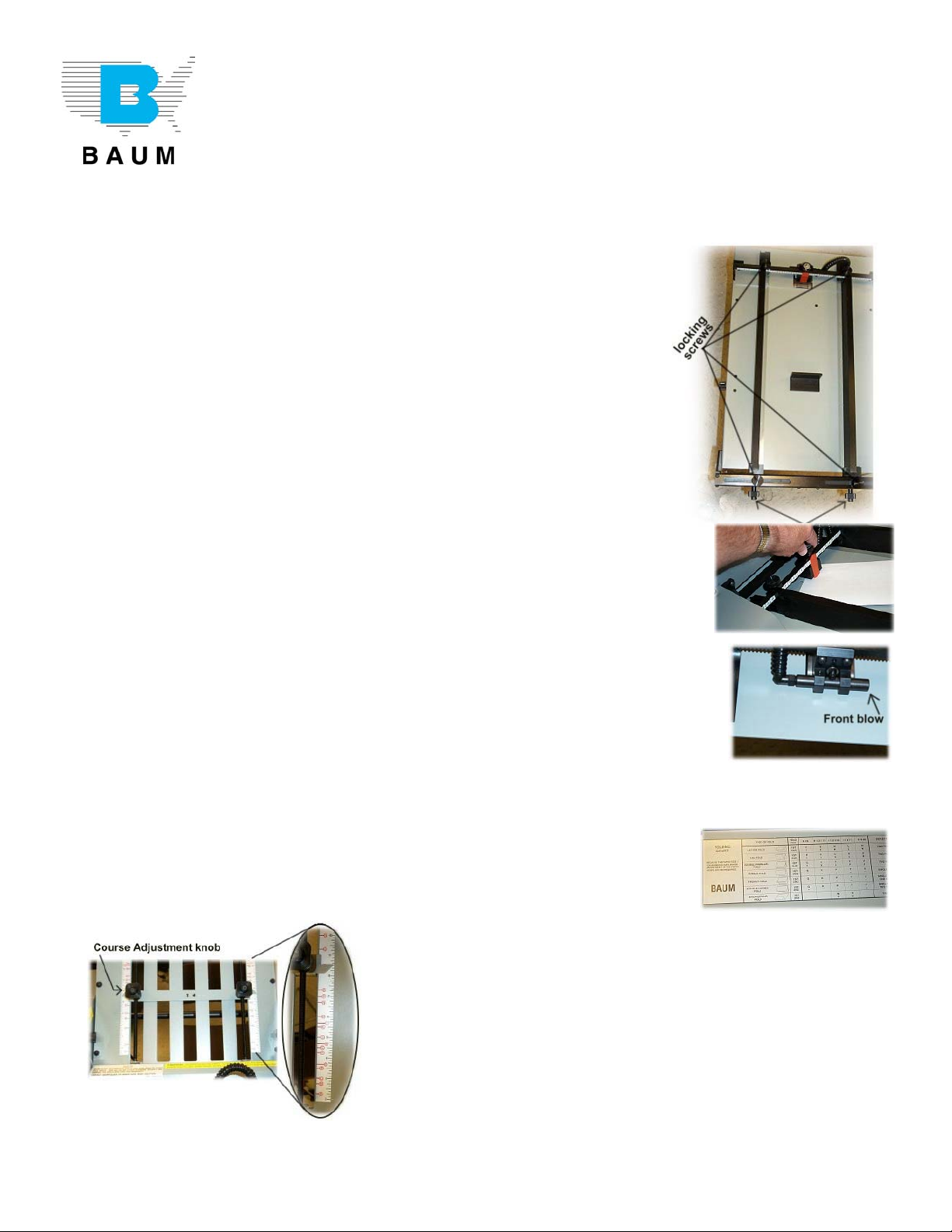
1. Loosen the locking screws on the feeder side guides. Turn the
knobs on the back of the Side guides and set them on 8 ½ on the
scale, actual 4 ½ “ from the center of the feeder. Lay a sheet of
paper you are running between the guides and it should slide down
but not have very much movement side to side. This is the key to
good folding. IF THE GUIDES ARE TOO TIGHT, IT WILL NOT
FEED WELL. If the guides are to loose, the fold will vary. If a fold
is always crooked, usually the cause is that the side guides are not
square with the number one fold roller. See appendix A for
correction. Set the magnetized angle stop at the back of the sheet.
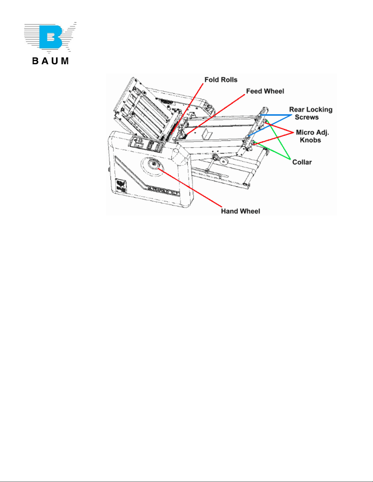
2. Insert two thickness of paper between the caliper tab and the
sucker wheel. Turn the gap knob counter-clockwise to tighten or
clockwise to loosen. Set the gap knob until there is a slight drag on the
paper. Remove the paper and the correct gap is now set. When you load
the feeder, the printing will be up.
3. The front blow will normally be set properly. If not, it should be set so it
separates the bottom sheets. The adjustment knob on the side of the
feeder is to set the blow in the side guide and front blow. Turn the knob to
the right to obtain more blow on the right side and front of the feed table.
Turn the knob to the left to obtain more blow on the left and reduce the
front blow.
4. Look on the folding chart on the stacker tray and locate 8 ½ x 11, fifth column over and letter fold
second line down. It shows the first fold plate is set on E, and the
second fold plate is set on E. On the fold plates approximately 3 ½ “
from the nose of the fold plate are the letter E (on both sides,) in a red
circle with a line from it. Depress the course adjustment knobs and
move the paper stop until it is on or close to the red line out
from the letter E. At the end away from the rolls of the
adjustment rods are micro adjustment knobs. You can move
these knobs to align the paper stops on the red line. Both fold
plates should have the open end toward the fold rollers and
the deflector away from the fold rollers. Both fold plate stops
are adjusted the same way.
(continued)

Set up instructions for the 714XLT
Baumfolder Corporation P.O. Box 728 1660 Campbell Rd, Sidney, Ohio USA 45365 Copyright © 2002
Phone 1-800-543-6107 or 1-937-492-1281 Fax 1-937-492-7280 email: Baumfolder@baumfolder.com
5. If you have a job where you want to fold in one plate only, pivot the
plate hold-down out of the way. Lift up slightly on the back of the
plate you are not using and pull toward you. Turn the plate end for
end and reinstall it with the deflector toward the fold rollers. Turn the
plate hold-downs down toward the fold plates to lock it in position.
6. The stacker has 3 ½, 5 ½, and 8 ½ printed on the
outside edges of the stacker. Run one sheet through
the folder and measure the length. Set the stacker
wheels so that the signature (folded sheet) is against
the wheels just as it clears the pull out tires on the slitter
shaft. Move the deflector assembly, (hold-downs), on
the black bar of the slitter shaft to guide the signature under the stacker wheels leaving enough
space between the stacker belt and the deflector for the signature
to move. The stacker wheels should ride on the stacker belt. To
move the stacker belt if necessary, loosen the setscrew in the drive
spool, and move it to the location needed. The belt and rear spool
can be slid over to line up with the front spool.
7. The operating controls consist of an Off/On power switch, which is an overload reset also. This
supplies power to the equipment. If the folder has a jam up and shuts off, turn the switch off and
back on again. The Pump Off/On switch is to turn the pump on
and off. The Speed Potentiometer controls the speed of the
folder. Turn to the right to speed the folder up or to the left to
slow the folder down. The counter to show the number of
sheets folded with a small button to reset the counter when you
change jobs. When you want to run a sheet/sheets, turn on
the power switch, then turn on the pump switch to run the
number of sheets you want to run, then turn off the pump. Use the pump switch to start and stop the
paper flow. If you change the speed of the folder, the length of the fold may also change. Check
the fold after any speed changes.
(continued)

Set up instructions for the 714XLT
Baumfolder Corporation P.O. Box 728 1660 Campbell Rd, Sidney, Ohio USA 45365 Copyright © 2002
Phone 1-800-543-6107 or 1-937-492-1281 Fax 1-937-492-7280 email: Baumfolder@baumfolder.com
8. Load the feeder, printing face up for header in, or face down for
header out, and run three signatures (sheets). You may have to
adjust the vacuum and or the blow. To adjust the vacuum, turn the
right knob on the on the right guard counter clock-wise to increase
and clock-wise to decrease vacuum. The knob on the left is the
blow adjustment.
9. Make any adjustments necessary with the micro adjustments. If you have a dog-ear, (corner of the
inside fold turned back), adjust the length of the inside fold so it is approximately 1/16” to 1/8” from
the second fold. Lengthening or shorting the number one fold plate can accomplish this.
10. If for any reason you will be folding in the second unit (8 page), always score after the fold is formed
in the slitter shafts. The score should be located where the second fold will be made.
11. If you want to do the second pass on the same folder, score on the first pass
through the folder. Move the side guide over close to the vacuum feed wheel.
The feed wheel should pick up the folded sheet within ¾” of the fold. You
may have to remove the front blow bar to get the side guide close enough to
the vacuum wheel. Turn the adj. knob on the side of the feeder to blow air
into the folder side (in the picture shown, that would be the right side)
** End of basic setup instructions *

Appendix A: Squaring Side Guides
on the 714XLT folders
If the fold is not folding straight or wrinkling:
Square the guide with the fold rollers.
1. Remove the number 1 fold plate (top fold plate).
2. Take an 11 x 17 sheet of paper that is cut square and lay on feed table against one of the side
guides.
3. Hand feed the sheet into the folder and watch the sheet come out of the first set of rolls. Watch
the sheet to see if it comes out square, or if one corner comes out before the other. If one corner
comes out before the other you know you are not feeding square.
4. Referencing the diagram above, loosen the rear locking screws on the back of the side guide,
then push in the micro-adj. knob and rotate the back of the side guide in the direction that the
back of the paper needs to move to square the side guide. Once you have moved the side guide
retighten the rear locking screws.
5. Repeat step 3 to see if the paper is now coming out square. If not repeat step 4 until side guide is
square.
6. When you get the side guide square then loosen the collar and rotate it until the micro-adj. knob
falls back on to it then retighten the collar.
7. Then align the other side guide to the first side guide using the square sheet of paper.
** End of Appendix A **
Baumfolder Corporation P.O. Box 728 1660 Campbell Rd, Sidney, Ohio USA 45365 Copyright © 2002
Phone 1-800-543-6107 or 1-937-492-1281 Fax 1-937-492-7280 email: Baumfolder@baumfolder.com

Appendix B: How to install a Perforator
on a Baum 714
** UNPLUG POWER SUPPLY BEFORE WORKING ON ANY FOLDER **
The perforator blade is sharp. Extra care should be exercised to protect you from
a cut by the perforator blade.
* Underlined items are shown/noted on diagram page.
1. On the air feed and the 714 AUTOFOLD units, disconnect the air and vacuum hose and on the
AUTOFOLD, disconnect the electrical connection to the feed table. Lift up the rear of the feed
table and lift it toward you to remove the feed table. Under the feed table and just prior to the
stacker is the slitter shaft assembly. On the left side of the slitter shaft assembly is a screw or a
plunger that tighten against the frame to remove endplay (movement from side to side). Loosen
the screw or plunger. Carefully lift both ends up even and toward you and lay the slitter shaft
assembly on a worktable.
2. Loosen the socket head bolt from the end of the tie bar that fastens the left slitter shaft boxing
to the complete assembly and remove the boxing from the slitter shafts.
3. Loosen the setscrew in the left pullout tire assembly and remove it from the top slitter shaft. Do
not remove the right pullout tire assembly.
4. To prepare the perforator blade, remove the two screws from the blade holder collar and lay the
perforator blade onto the side of the blade holder collar and align the screw holes in the collar and
replace the two screws to fasten the perforator blade to the blade holder collar. Do not tighten the
screws at this point.
5. Slide the perforator blade and the blade holder collar to the center of the top slitter shaft and
tighten the brass point set screw. Now tighten the two setscrews on the blade holder collar.
6. Replace the left pullout tire assembly on the top slitter shaft and place it about three inches from
the perforator blade and tighten the brass point set screw to secure it to the top slitter shaft.
7. Keep all the brass point set screws in a line so if you have to move any one of them later, you do
not have to keep turning the shafts.
8. Install the perforator stripper on the tie bar so it comes from the front of the tie bar and down
and between the perforator blade and the bottom slitter shaft. Do not tighten yet.
9. Remove the left pullout tire assembly from the bottom slitter shaft by loosen the brass point set
screw and sliding it off the bottom slitter shaft.
(Continued)
Baumfolder Corporation P.O. Box 728 1660 Campbell Rd, Sidney, Ohio USA 45365 Copyright © 2002
Phone 1-800-543-6107 or 1-937-492-1281 Fax 1-937-492-7280 email: Baumfolder@baumfolder.com

How to install a perforator on a 714XLT
(Continued from previous page)
10.Slide the female perforator collar until the wide groove of the female collar is under the
perforator blade. Leave it loose for now. The perforator stripper should be between the
perforator blade assembly and the female perforator collar.
11.Slide the left pullout tire you just removed back on the bottom slitter shaft until it is directly under
the left pullout tire on the top slitter shaft and tighten the brass point set screw to secure the
pullout tire assembly to the shaft.
12.Replace the left slitter shaft boxing on the slitter shaft in reverse order as you removed them.
Install the socket head bolt that fastens the left slitter shaft boxing to the slitter shaft assembly
and tighten it.
13.Move the female perforator collar until the sharp edge of the blade is against the edge of the
wide groove in the female perforator collar and tighten the brass point set screw in the collar to
secure it in place. The blade against the edge of the groove creates a scissors action as the shafts
turn. THE PERFORATOR BLADE IS SHARP. CAUTION SHOULD BE EXERCISED WHEN
WORKING AROUND THE PERFORATOR BLADE.
14.Replace the slitter shaft assembly in reverse order as it was removed. Extra care should be made
to insure the slitter shaft boxings are secure on all four pins in the frame and the gears all mash
properly. Turn the hand wheel a couple times to insure the slitter shaft assembly is in proper
position.
15.Raise the perforator stripper until it is not rubbing the blade holder and along the side of the
perforator blade and it will allow a sheet of paper to go under the stripper and above the female
perforator collar without jamming them lock it in place. The purpose of the stripper is to strip the
sheet off of the perforator blade otherwise the sheet would wrap around the top slitter shaft.
16.Replace the feed table in reverse order it was removed. Again turn the hand wheel to be sure
every thing is in the proper place and nothing is rubbing, run a sheet through to see if the
perforator is in the proper location. If not loosen the setscrews and move the assemblies where
you want them on the shafts and lock with the brass point setscrews. Turn the hand wheel to
insure nothing is rubbing and check it again.
Continued on next page…
Baumfolder Corporation P.O. Box 728 1660 Campbell Rd, Sidney, Ohio USA 45365 Copyright © 2002
Phone 1-800-543-6107 or 1-937-492-1281 Fax 1-937-492-7280 email: Baumfolder@baumfolder.com

714 Slitter Shaft Assembly,
setup for perforating
Part Number Information
1 Pullout Tire Assy. 06404
Sheet Pullout Sleeve 06997
Pullout Tire 06402
2 Perforator 07791
3 Blade holder 06411
4 Screw – Felstr 10-24 x 3/8 20312
5 Female Perforator Collar 06799
6 Screw Brass Point tip 20438
7 Perforator Stripper S45297
** End of Appendix B **
Baumfolder Corporation P.O. Box 728 1660 Campbell Rd, Sidney, Ohio USA 45365 Copyright © 2002
Phone 1-800-543-6107 or 1-937-492-1281 Fax 1-937-492-7280 email: Baumfolder@baumfolder.com

Appendix C: How to install or Remove
Score Blades on a Baum 714
** UNPLUG POWER SUPPLY BEFORE WORKING ON ANY FOLDER **
The score blades are sharp. Extra care should be exercised to protect you from a cut
by the score blades.
BEFORE BEGINNING: On Air Feed and 714 AUTOFOLD units, disconnect the air and
vacuum hose, and on the AUTOFOLD, disconnect the electrical connection to the feed
table.
1. Lift up on the rear of the feed table and lift toward you to remove the feed table.
2. Under the feed table and just prior to the stacker is the slitter shaft assembly. On the left side of
the slitter shaft assembly is a screw or plunger that tightens against the frame to remove endplay
(movement from side to side). Loosen screw or pull plunger.
3. Carefully lift both ends up even and then towards you and lay the slitter shaft assembly on a
worktable with the rubber pullout tires toward the worktable top.
4. Loosen the socket head bolt from the end of the tie bar that fastens the left slitter shaft boxing
to the slitter shaft assembly. Remove the slitter shaft boxing from the slitter shafts.
5. Loosen the setscrew on the left pullout tire assembly and remove it from the top slitter shaft.
Leave the right pullout tie assembly in place.
6. To prepare the score blade assembly remove the two screws from the blade holder collar and
lay the score blade on the side of the blade holder collar and align the holes in the score blade
with the blade holder collar and replace the two screws. Do not tighten them now.
7. Slide the score blade and blade holder collar onto the top slitter shaft to the center of the top slitter
shaft and tighten the setscrew in the blade holder collar to lock it in position, and then tighten the
two screws to insure the score blade is tight against the blade holder collar.
8. Replace the left pullout tire assembly on the top slitter shaft and place it approximately three
inches from the score blade and tighten the setscrew to lock it in place. Keep all setscrews in line
so if you need to move them, you will not have to keep turning the slitter shaft.
9. Remove the left pullout tire assembly from the bottom slitter shaft.
10.Slide the score collar assembly on to the bottom slitter shaft until the score blade aligns with the
middle on the one-inch rubber in the score collar assembly. Tighten the setscrew to lock the
score collar in place.
(Continued)
Baumfolder Corporation P.O. Box 728 1660 Campbell Rd, Sidney, Ohio USA 45365 Copyright © 2002
Phone 1-800-543-6107 or 1-937-492-1281 Fax 1-937-492-7280 email: Baumfolder@baumfolder.com

How to install or remove score
blades on a 714XLT
(Continued from previous page)
11.Slide the left pullout tire assembly directly under pullout tire on the top slitter shaft and tighten the
setscrew to hold the pullout assembly in place.
12.Replace the left slitter shaft boxing and tighten the socket head bolt into the tie bar
13.Replace slitter shaft assembly into the folder in reverse order it was removed.
14.Replace feed table in reverse order removed.
15.Turn the folder by hand to insure nothing is loose or rubbing and that everything is free.
16.Set up folder and run sheet through by hand and move perforator into position desired and lock
any setscrews you may have moved. Turn another sheet through by hand, and if ok, plug in
folder.
17.Turn on and run a sheet through and check fold and location. If ok run job.
Continued on next page…
Baumfolder Corporation P.O. Box 728 1660 Campbell Rd, Sidney, Ohio USA 45365 Copyright © 2002
Phone 1-800-543-6107 or 1-937-492-1281 Fax 1-937-492-7280 email: Baumfolder@baumfolder.com

714 Slitter Shaft Assembly,
setup for scoring
Part Number Information
Left Pullout Tire Assembly……... 06404
Left Paper Deflector Assembly… 262-453-BG-01
** End of Appendix C **
Baumfolder Corporation P.O. Box 728 1660 Campbell Rd, Sidney, Ohio USA 45365 Copyright © 2002
Phone 1-800-543-6107 or 1-937-492-1281 Fax 1-937-492-7280 email: Baumfolder@baumfolder.com

BAUM BAUM EASY-FAX Order Form
1660 Campbell Road Fax #: 1-800-452-0947
Sidney, OH 45365 or - 1-937-497-8301
PH: 1-800-543-6107 If you need information or assistance identifying part numbers please
-or- 1-937-778-9636 call our Parts department toll free at 800-543-6107 between the hours
of 8 a.m. and 5 p.m. EST
Customer Information : For Billing Ship-toInformation:
Acct #: ___________________ P.O. Nbr: __________________________
Company: ______________________________________ Company: _______________________________________
Contact: ______________________________________ Contact _______________________________________
Address: ______________________________________ Address: _______________________________________
City / St: ______________________________________ City / St: _______________________________________
Zip: _____________________ Zip: _____________________
Phone: _______________________________ Phone: _______________________________
IMPORTANT: If you do not indicate order status, order will be assumed to be “Normal”
ORDER STATUS: Emergency Order ______ Rush Order ______ Normal Order ______
Qty Part Number Description * Model# & Serial #
_____OK to ship C.O.D. if necessary
Shipping Instructions: (mark only one)
_____UPS Ground _____UPS 2nd Day Air _____UPS Next Day _____Federal Express _____Truck ____Other ___________________
(Please specify)
Charge Card Information: _____VISA _____Mastercard Name on Card: ______________________________________________
Expiration Date: ____________ Phone #: ________________________
Card #: ____________________________________________________
* For Machines under Warranty you MUST supply Serial# and Model# above
Other Baum Folding Machine manuals