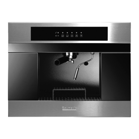
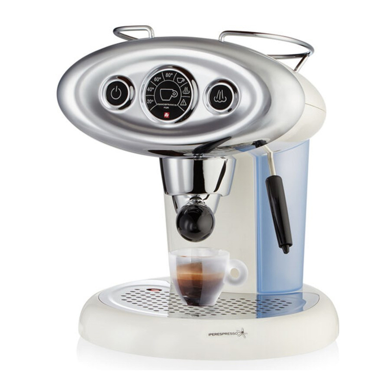
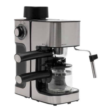
Baumatic BEC460SS User manual

SERVICE MANUAL
Baumatic Ltd BEC460SS / BEC461SS coffee machine

CONTENTS
A)SAFETY
B) SCOPE OF THIS MANUAL
C) DIMENSIONS
D) HYDRAULIC DIAGRAM
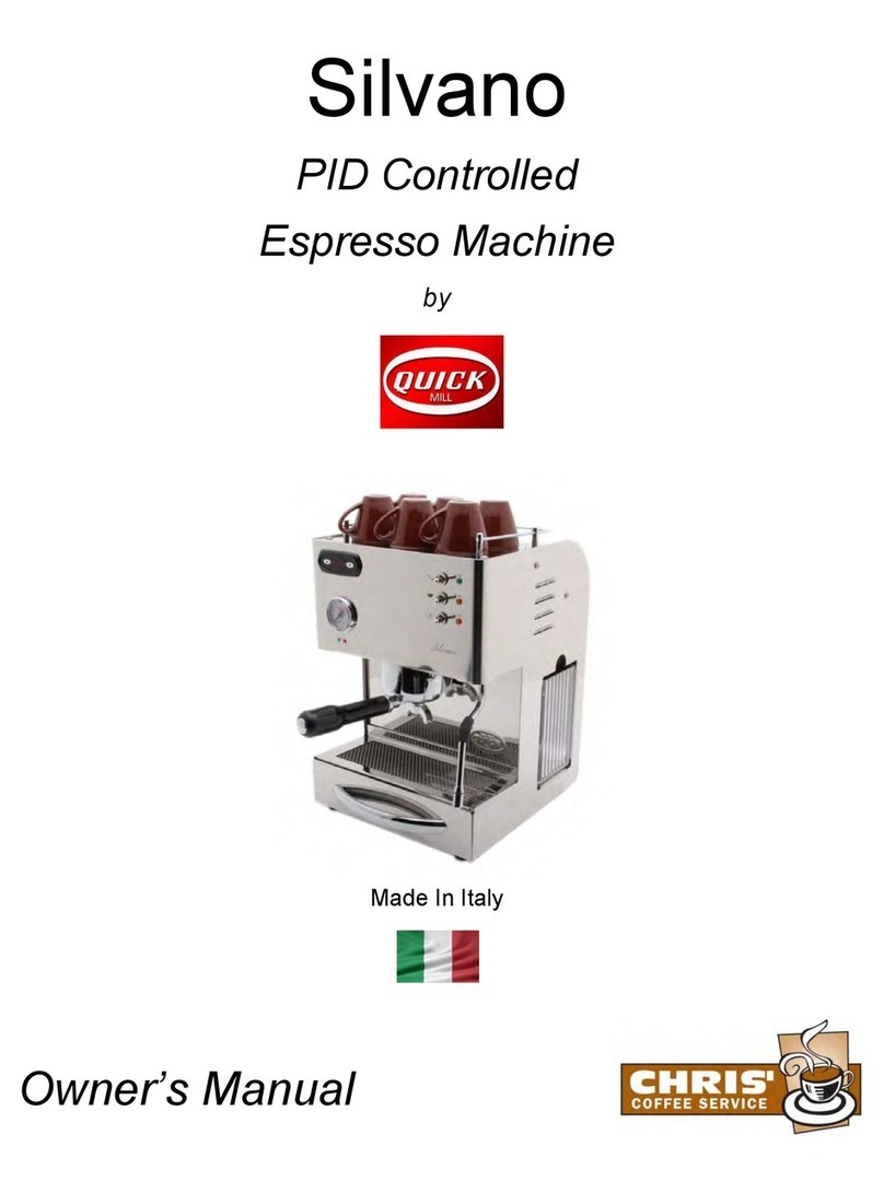
E) WIRING DIAGRAM
F) STRUCTURE
1) general accessibility
2) automatic unit compartment accessibility
3) component compartment accessibility
G) QUICK COUPLING CONNECTIONS
H) SAFETY THERMOSTAT RESET
1

A / SAFETY
Before accessing the internal components and, in general, before doing any jobs on the appliance,
make sure the power plug has been disconnected and that any heated parts have cooled down.
IMPORTANT: The appliance in question has metal parts. We therefore advise being very careful
when handling or doing jobs on these to avoid scratches, abrasions or cuts.
B / SCOPE OF THIS MANUAL
This manual has been compiled for technicians with the skills required to repair coffee machines
for home use.
Its purpose is to provide details of a general nature regarding the product, to make any jobs and
maintenance easier.
C / DIMENSIONS
2

D / HYDRAULIC DIAGRAM
oth circuits, hot water/steam and coffee, use the same pump. Hence functions must be performed
ort description of the dynamics and operating sequences concerning the three main functions:
offee: required dose has been selected and the cycle has been started, powder preparation and
- Hot water: been selected, keep the start key pressed for the required dispensing time. er pushed
luid still in the
team: function has been selected, keep the start key pressed for the required dispensing time. arted, the
luid still in the
B
individually.
Below is a sh
-C
Once the
automatic unit positioning is followed by pump operation and the opening of the two solenoid valves. At this
point, the water flows through the flow meter which determines the dose, through the pump, the first solenoid
valve, the heat exchangers for the coffee and the second solenoid valve and then enters the plastic body of
the automatic unit. Here, after passing through the coffee pod, the coffee is collected by the brass part
mounted on the same heat exchanger from which it protrudes thanks to a silicone pipe and reaches the
dispenser. Once the cycle has terminated, the solenoid valves de-energize and drain the fluid still in the
circuit into the drip tray.
Once the function has
Upon starting the appliance, the pump and the hot water/steam solenoid valve are started, the wat
by the pump flows through the first solenoid valve and then enters the hot water/steam exchanger.
Once it has crossed the exchanger, it is conveyed to the hot water/steam outlet pipe junction.
Once the start key is released, the solenoid valve de-energizes and switches over so the f
circuit is drained into the drip tray.
-S
Once the
When the appliance is switched on, the pump and the hot water/steam solenoid valve are st
solenoid valve in normal operation and the pump by means of short but frequent pulses. The water pushed
by the pump flows through the first solenoid valve and then enters the hot water/steam exchanger.
Once it has crossed the exchanger, it is conveyed to the hot water/steam outlet pipe junction.
Once the start key is released, the solenoid valve de-energizes and switches over so the f
circuit is drained into the drip tray.
3

E / WIRING DIAGRAM
4

F / STRUCTURE
1) GENERAL ACCESSIBILITY
BEFORE PROCEEDING, DISCONNECT THE MACHINE FROM THE POWER MAINS
To work inside the appliance, proceed to dismantle as follows:
Loosen the screws on the upper part of the appliance
Raise and remove the lid as shown in the photo.
5

H
ED
B
C
A
GF
Once the lid has been removed, the following components can be accessed:
-A: Top part of the automatic unit to do jobs on the safety thermostat , temperature probe, connections and
pipes.
-B: Coffee and steam circuit solenoid valves for jobs on coils or pipes.
-C: Electronic board for checking cables or changing fuses.
-D: Flow meter for internal cleaning or replacement.
-E: Anti radio disturbance filter for checks or replacements.
-F: Steam junction for replacing O-ring or jobs on pipe or connection.
-G: Telescopic dispenser for checking support or replacement apparatus.
-H: Steam, hot water exchanger for jobs on safety thermostat, temperature probe or pipes.
2) AUTOMATIC UNIT COMPARTMENT ACCESSIBILITY
6

This compartment can be accessed in two ways: by means of the service door for checking the apparatus or
by removing the right section of the bodywork for bigger jobs.
-SERVICE DOOR:
Only technical personnel must access the appliance
through the service door.
For greater safety, the closing screw is of the TORX
M4x10 type and consequently a suitable screwdriver is
required.
Remove the screw and open the door to make necessary
inspections.
-REMOVAL OF RH BODYWORK:
Remove the two screws on the rear.
Remove the four screws on the side.
7

Remove the five screws on the lower section.
Remove the grinding regulation knob as shown.
Now the entire RH section can be removed and
access obtained to the unit and the micro
switches of the side doors and dredge
unloading.
The photo shows the two micro switches of the
door and dredge unloading.
The micro with three attached wires also sends
a signal to the board for dredge count reset.
8

The photo shows the two micro switches of the side door. These disconnect the entire power circuit
downstream of the master switch.
If jobs have to be done on the automatic
unit, disconnect the delivery and exit pipes
of the exchanger, proceeding as indicated
under “QUICK-COUPLING
CONNECTIONS”.
Remove the power connections.
9

Disconnect the silicone pipe from the brass part located at the centre of the exchanger cover.
Loosen the upper retention screw of the unit
introducing the tool through the holes shown
in the illustration.
Loosen the lower retention screw as shown in the
illustration.
10

Now the unit can be removed by pulling it towards you
When fitting the automatic unit back on, be
careful to correctly fit the pin of the same
unit on the motor shaft as shown in the
illustration
3) COMPONENT
COMPARTMENT
ACCESSIBILITY
11

Loosen the two retention screws of the tank support band by inserting the tool through the holes shown in
the illustration.
Once the tank support has been removed, loosen
the two side screws as shown in the illustration.
Loosen the retention nut of the pump-
grinder support indicated in the photo.
12

Loosen the two screws shown in the photo.
Loosen the screw shown in the photo.
Remove the five retention screws shown in
the bottom of the machine.
13

After slightly shifting the left plate disconnect the wires of the water sensor.
Remove the left side bodywork
Besides now being able to freely access all
the machine parts, the main fuse located on
the base can also be changed.
G) QUICK-COUPLING
CONNECTIONS
14

The quick-coupling connections allow quickly performing all maintenance jobs on the hydraulic connections
of the machine.
To use these correctly, do not use tools but
only your fingers.
The first thing to do to disconnect a hose is
to lightly press on the edge of the connector.
Afterwards, simply apply a light force on
the hose to remove this.
H) SAFETY THERMOSTAT
RESET
15

The two safety thermostats on the coffee exchanger and on the steam/hot water exchanger can be manually
reset.
To reset, press the top button.
16
Other manuals for BEC460SS
1
This manual suits for next models
1
Table of contents
Other Baumatic Coffee Maker manuals