Baumer Hübner HOG 60 User manual

HOG 60
Drehimpulsgeber
Incremental Encoder
MB76 hog60_mb (07A2)
Montage- und Betriebsanleitung
Installation and operating instructions

hog60_mb (07A2) MB76
Inhaltsverzeichnis
Inhaltsverzeichnis
1Allgemeine Hinweise ...................................................................................................................................................1
2Betrieb in explosionsgefährdeten Bereichen .............................................................................................3
3Sicherheitshinweise .....................................................................................................................................................5
4Vorbereitung ......................................................................................................................................................................7
4.1 Lieferumfang ........................................................................................................................................................7
4.2 zur Montage erforderlich (nicht im Lieferumfang enthalten) ........................................................8
5Montage ................................................................................................................................................................................8
5.1 Schritt 1 ...................................................................................................................................................................8
5.2 Schritt 2 ...................................................................................................................................................................9
5.3 Anbauhinweis .......................................................................................................................................................9
5.4 Schritt 3 ................................................................................................................................................................ 10
6Maßzeichnung ................................................................................................................................................................11
7Elektrischer Anschluss .......................................................................................................................................... 12
7.1 Ausführung mit Flanschdose und Stecker ......................................................................................... 12
7.1.1 Kabelanschluss ......................................................................................................................................... 12
7.1.2 Pinbelegung Flanschdose
HOG 60 DN … CI, DN ... TTL und DN … R ..........................13
7.1.3 Kabel HEK 8 (Zubehör) ............................................................................................................................... 14
7.1.2 Option: Ausführung mit Kabelverschraubung und Kabel ........................................................... 14
7.2.1 Kabelanschluss ......................................................................................................................................... 14
7.2.2 Kabelbelegung
HOG 60 DN … CI, DN ... TTL und DN … R ...................................................15
7.3 Ausgangssignale ............................................................................................................................................. 15
8Demontage ...................................................................................................................................................................... 16
8.1 Schritt 1 ................................................................................................................................................................ 16
8.2 Schritt 2 ................................................................................................................................................................ 16
8.3 Schritt 3 ................................................................................................................................................................ 17
8.4 Schritt 4 ................................................................................................................................................................ 17
9Zubehör .............................................................................................................................................................................. 18
10 Technische Daten ....................................................................................................................................................... 19
10.1 Mechanische Daten ....................................................................................................................................... 19
10.2 Elektrische Daten ........................................................................................................................................... 19
11 Anhang: EU-Konformitätserklärung .............................................................................................................. 21

MB76 hog60_mb (07A2)
Table of contents
Table of contents
1General notes ...................................................................................................................................................................2
2Operation in potentially explosive environments ....................................................................................4
3Security indications .....................................................................................................................................................6
4Preparation .........................................................................................................................................................................7
4.1 Scope of delivery ...............................................................................................................................................7
4.2 required for mounting (not included in scope of delivery) ............................................................8
5Mounting ..............................................................................................................................................................................8
5.1 Step 1 .......................................................................................................................................................................8
5.2 Step 2 .......................................................................................................................................................................9
5.3 Mounting instruction .........................................................................................................................................9
5.4 Step 3 .................................................................................................................................................................... 10
6Dimension drawing .....................................................................................................................................................11
7Electrical connection ................................................................................................................................................ 12
7.1 Versionwithangesocketandconnector......................................................................................... 12
7.1.1 Cable connection ..................................................................................................................................... 12
7.1.2 Flangesocketpinassignment
HOG 60 DN … CI, DN ... TTL and DN … R .................13
7.1.3 Cable HEK 8 (accessory) ........................................................................................................................... 14
7.2 Option: Version with screwed gland and cable ............................................................................... 14
7.2.1 Cable connection ..................................................................................................................................... 14
7.2.2 Cable assignment
HOG 60 DN … CI, DN ... TTL and DN … R ............................................15
7.3 Output signals ................................................................................................................................................... 15
8Dismounting ................................................................................................................................................................... 16
8.1 Step 1 .................................................................................................................................................................... 16
8.2 Step 2 .................................................................................................................................................................... 16
8.3 Step 3 .................................................................................................................................................................... 17
8.4 Step 4 .................................................................................................................................................................... 17
9Accessories .................................................................................................................................................................... 18
10 Technical data ............................................................................................................................................................... 20
10.1 Mechanical data .............................................................................................................................................. 20
10.2 Electrical data ...................................................................................................................................................20
11 Appendix: EU Declaration of conformity .................................................................................................... 22

1 hog60_mb (07A2) MB76
1Allgemeine Hinweise
1Allgemeine Hinweise
1.1 Der Drehimpulsgeber HOG 60 ist ein opto-elektronisches Präzisionsmessgerät, das mit
Sorgfalt nur von technisch qualiziertem Personal gehandhabt werden darf.
1.2 Die zu erwartende Lebensdauer des Gerätes hängt von den Kugellagern ab, die mit einer
Dauerschmierung ausgestattet sind.
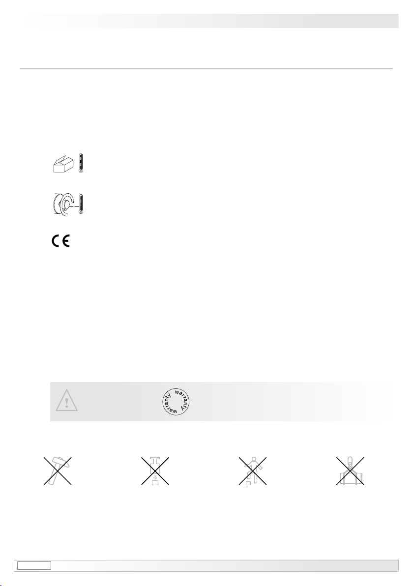
1.3 Der Lagertemperaturbereich des Gerätes liegt zwischen -15 °C bis +70 °C,
bedingt durch die Styroporverpackung.
1.4 Der Betriebstemperaturbereich des Gerätes liegt zwischen -30 °C bis +85 °C,
am Gehäuse gemessen.
1.5 EG Konformitätserklärung gemäß Richtlinie 89/336/EWG Artikel 10 - sowie Anhang 1
(EMV-Richtlinie).
1.6 Das Gerät ist zugelassen nach UL (gilt nicht für Einsatz in explosionsgefährdeten Bereichen).
1.7 Wir gewähren 2 Jahre Gewährleistung im Rahmen der Bedingungen des Zentralverbandes der
Elektroindustrie (ZVEI).
1.8 Reparaturen oder Wartungsarbeiten, die das Öffnen des Gebers erfordern, sind vom Herstel-
ler durchzuführen.
1.9 Bei Rückfragen bzw. Nachlieferungen sind die auf dem Typenschild des Gerätes angege-
benen Daten, insbesondere Typ und Seriennummer, unbedingt anzugeben.
Achtung!
Beschädigung des auf dem Gerät bendlichen Siegels führt zu
Gewährleistungsverlust.
MB76 hog60_mb (07A2) 2
General notes 1
1General notes
1.1 The incremental encoder HOG 60 is an opto electronic precision measurement device which
mustbehandledwithcarebyskilledpersonnelonly.
1.2 The expected operating life of the device depends on the ball bearings, which are equipped with
a permanent lubrication.
1.3 The storage temperature range of the device is between -15 °C and +70 °C,
conditionedbythestyrofoampacking.
1.4 The operating temperature range of the device is between -30 °C and +85 °C,
measured at the housing.
1.5 EU Declaration of Conformity meeting Council Directive 89/336/EEC art. 10 and annex 1
(EMC Directive).
1.6 The device is UL approved (not applicable for operation in potentially explosive atmospheres).
1.7 We offer a 2-year warranty in accordance with the regulations of the ZVEI (Central Association of
the German Electrical Industry).
1.8 Repair or maintenance work that requires opening the encoder must be carried out by the
manufacturer.
1.9 In the event of queries or subsequent deliveries, the data on the device type label must be
quoted, especially the type designation and the serial number.
Warning!
Damaging the seal on the device invalidates warranty.

3 hog60_mb (07A2) MB76
2Betrieb in explosionsgefährdeten Bereichen
Das Gerät entspricht der Norm EG-Richtlinie 94/9/EG für
explosionsgefährdete Bereiche.
Der Einsatz ist gemäß den
Gerätekategorien 3 G (Ex-Atmosphäre Gas) und 3 D (Ex-Atmosphäre
Staub) zulässig.
Gerätekategorie 3 G: - Ex-Kennzeichnung: II 3G Ex nA T4 X
- Normenkonformität: DIN EN 60079-15: 2004
- Zündschutzart: nA
- Temperaturklasse: T4
- Gerätegruppe: II
Gerätekategorie 3 D: - Ex-Kennzeichnung: II 3D Ex IP65 A22 T135°C X
- Normenkonformität: DIN EN 61241-1: 2004
DIN EN 61241-14: 2004
- Schutzprinzip: Schutz durch Gehäuse
- max. Oberächentemperatur: +135 °C
- Gerätegruppe: II
Der Einsatz in anderen explosionsgefährdeten Bereichen ist nicht zulässig.
2.1 Der maximale Umgebungstemperaturbereich für den Einsatz des Gerätes im Ex-Bereich
beträgt -20 °C bis +40 °C.
2.2 Der Anlagenbetreiber hat zu gewährleisten, dass eine mögliche Staubablagerung eine maxima-
le Schichtdicke von 5 mm nicht überschreitet (gemäß DIN EN 61241-14: 2004).
2.3 Eine gegebenenfalls an anderen Stellen aufgeführte UL-Listung gilt nicht für den Einsatz im
Ex-Bereich.
2.4 Das Gerät darf nur in Betrieb genommen werden, wenn ...
die Angaben auf dem Typenschild des Gerätes mit dem zulässigen Ex-Einsatzbereich vor
Ort übereinstimmen (Gerätegruppe, Kategorie, Zone, Temperaturklasse bzw. maximale
Oberächentemperatur),
die Angaben auf dem Typenschild des Gerätes mit dem Spannungsnetz übereinstimmen,
das Gerät unbeschädigt ist (keine Schäden durch Transport und Lagerung) und
sichergestellt ist, dass keine explosionsfähige Atmosphäre, Öle, Säure, Gase, Dämpfe,
Strahlungen etc. bei der Montage vorhanden sind.
2.5 An Betriebsmitteln, die in explosionsgefährdeten Bereichen eingesetzt werden, darf keine Ver-
änderung vorgenommen werden. Reparaturen dürfen nur von autorisierten Stellen ausgeführt
werden.
Das Gerät ist entsprechend den Angaben in der Montage- und Betriebsanlei-
tung zu betreiben. Die für die Verwendung bzw. den geplanten Einsatzzweck
zutreffenden Gesetze, Richtlinien und Normen sind zu beachten.
–
–
–
–
2Betrieb in explosionsgefährdeten Bereichen

MB76 hog60_mb (07A2) 4
2Operation in potentially explosive environments
The device complies with the EU standard 94/9/EG for potentionally explosive atmospheres.
It can be used in accordance with equipment categories 3 G (explosive gas atmosphere) and
3 D (explosive dust atmosphere).
Equipment category 3 G: - Ex labeling: II 3G Ex nA T4 X
- Conforms to standard: (DIN) EN 60079-15: 2004
- Type of protection: nA
- Temperature class: T4
- Group of equipment: II
Equipment category 3 D: - Ex labeling: II 3D Ex IP65 A22 T135°C X
- Conforms to standard: (DIN) EN 61241-1: 2004
(DIN) EN 61241-14: 2004
- Protective principle: Protection by enclosure
- max. surface temperature: +135 °C
- Group of equipment: II
The operation in other explosive atmospheres is not permissible.
2.1 In Ex areas the device must only be used within the ambient temperature range from -20 °C to
+40 °C.
2.2 The plant operator must ensure that any possible dust depositdoesnotexceedathicknessof
5 mm, in accordance with (DIN) EN 61241-14: 2004.
2.3 An UL listing that may be stated elsewhere is not valid for use in explosive environ-
ments.
2.4 Operation of the device is only permissible when ...
the details on the type label of the device match the on-site conditions for the permissible
Ex area in use (group of equipment, equipment category, zone, temperature class or maxi-
mum surface temperature),
thedetailonthetypelabelofthedevicematchtheelectricalsupplynetwork,
the device is undamaged (no damage resulting from transport or storage), and
ithasbeencheckedthatthereisnoexplosiveatmosphere,oils,acids,gases,vapors,radi-
ation etc. present during installation.
2.5 Itisnotpermissibletomakeanyalterationtoequipmentthatisusedinpotentiallyexplosive
environments. Repairs may only be carried out by authorized authorities.
The device must be operated in accordance with the stipulations of the instal-
lation and operating instructions. The relevant laws, regulations and standards
for the planned application must be observed.
–
–
–
–
Operation in potentially explosive environments 2

5 hog60_mb (07A2) MB76
3Sicherheitshinweise
3Sicherheitshinweise
3.1 Verletzungsgefahr durch rotierende Wellen
Haare und Kleidungsstücke können von rotierenden Wellen erfasst werden.
Vor allen Arbeiten alle Betriebsspannungen ausschalten und Maschinen stillsetzen.
3.2 Zerstörungsgefahr durch elektrostatische Auadung
Die elektronischen Bauteile im Drehgeber sind empndlich gegen hohe Spannungen.
Steckkontakte und elektronische Komponenten nicht berühren.
Ausgangsklemmen vor Fremdspannungen schützen.
Max. Betriebsspannung nicht überschreiten.
3.3 Zerstörungsgefahr durch mechanische Überlastung
Eine starre Befestigung kann zu Überlastung durch Zwangskräfte führen.
Die Beweglichkeit des Drehgebers niemals einschränken! Unbedingt die Montagehinweise
beachten.
Die vorgegebenen Abstände und/oder Winkel unbedingt einhalten.
3.4 Zerstörungsgefahr durch mechanischen Schock
Starke Erschütterungen, z. B. Hammerschläge, können zur Zerstörung der Abtastung führen.
Niemals Gewalt anwenden. Bei sachgemäßer Montage lässt sich alles leichtgängig zusam-
menfügen.
Für die Demontage geeignetes Abziehwerkzeug benutzen.
3.5 Zerstörungsgefahr durch Verschmutzung
Schmutz kann im Drehgeber zu Kurzschlüssen und zur Beschädigung der optischen Abtastung
führen.
Während aller Arbeiten am Drehgeber auf absolute Sauberkeit achten.
Bei der Demontage niemals Öl oder Fett in das Innere des Drehgebers gelangen lassen.
3.6 Zerstörungsgefahr durch klebende Flüssigkeiten
Klebende Flüssigkeiten können die optische Abtastung und die Lager beschädigen. Die Demon-
tage eines mit der Achse verklebten Drehgebers kann zu dessen Zerstörung führen.
3.7 Explosionsgefahr
Der Drehgeber darf in explosiongefährdeten Bereichen der Kategorien 3 D und 3 G eingesetzt
werden. Der Betrieb in anderen explosionsgefährdeten Bereichen ist nicht zulässig.
•
•
•
•
•
•
•
•
•
•

MB76 hog60_mb (07A2) 6
Security indications 3
3Security indications
3.1 Risk of injury due to rotating shafts
Hair and clothes may become tangled in rotating shafts.
Beforeallworkswitchoffalloperatingvoltagesandensuremachineryisstationary.
3.2 Risk of destruction due to electrostatic charge
Electronic parts contained in the incremental encoder are sensitive to high voltages.
Do not touch plug contacts or electronic components.
Protect output terminals against external voltages.
Do not exceed max. operating voltage.
3.3 Risk of destruction due to mechanical overload
Rigid mounting may give rise to constraining forces.
Never restrict the freedom of movement of the incremental encoder. The installation instruc-
tions must be followed.
Itisessentialthatthespeciedclearancesand/oranglesareobserved.
3.4 Risk of destruction due to mechanical shock
Violentshocks,e.g.duetohammerimpacts,canleadtothedestructionoftheopticalsensingsystem.
Never use force. Assembly is simple when correct procedure is followed.
Use suitable puller for disassembly.
3.5 Risk of destruction due to contamination
Dirt penetrating inside the incremental encoder can cause short circuits and damage the optical
sensing system.
Absolutecleanlinessmustbemaintainedwhencarryingoutanyworkattheincrementalencoder.
When dismantling, never allow lubricants to penetrate the incremental encoder.
3.6 Risk of destruction due to adhesive uids
Adhesiveuidscandamagetheopticalsensingsystemandthebearings.Dismountinganincre-
mental encoder, secured to a shaft by adhesive may lead to the destruction of the unit.
3.7 Explosion risk
You can use the incremental encoder in areas with explosive atmospheres of category 3 D and
3 G. The operation in other explosive atmospheres is not permissible.
•
•
•
•
•
•
•
•
•
•
7 hog60_mb (07A2) MB76
4Vorbereitung / Preparation
4Vorbereitung
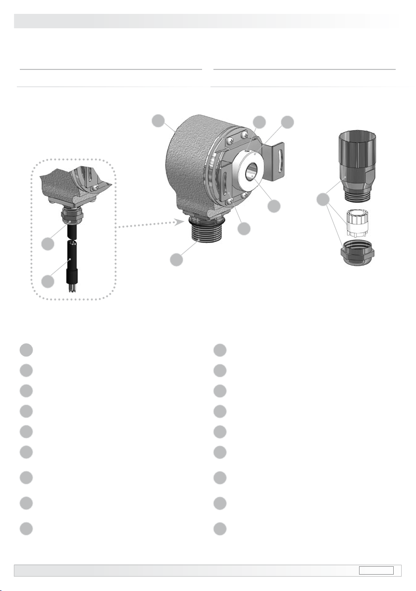
4.1 Lieferumfang
4Preparation
4.1 Scope of delivery
1Gehäuse HOG 60
2Hohlwelle HOG 60
3Klemmring
4Gewindestift M4x8
5Kupplungsblech mit Schrauben
6Flanschdose 12polig (Stiftkontakte)
(siehe Abschnitt 7.1.1 und 7.1.2)
7Stecker 12polig (Buchsenkontakte)
(siehe Abschnitt 7.1.1)
8Option: Kabelverschraubung M12x1,5
(siehe Abschnitt 7.2.1)
9Option: Anschlusskabel
(siehe Abschnitt 7.2.1 und 7.2.2)
1Housing HOG 60
2Hollow shaft HOG 60
3Clamping ring
4Grubscrew M4x8
5Coupling plate with screws
6Flangesocket12pin(malecontacts)
(see section 7.1.1 and 7.1.2)
7Connector (female contacts)
(see section 7.1.1)
8Option: Screwed gland M12x1,5
(see section 7.2.1)
9Option: Connecting cable
(siehe Abschnitt 7.2.1 and 7.2.2)
1
2
34
5
7
6
8
9
MB76 hog60_mb (07A2) 8
Vorbereitung - Montage / Preparation - Mounting 4-5
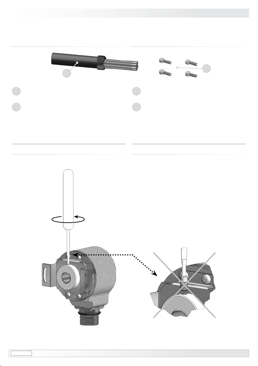
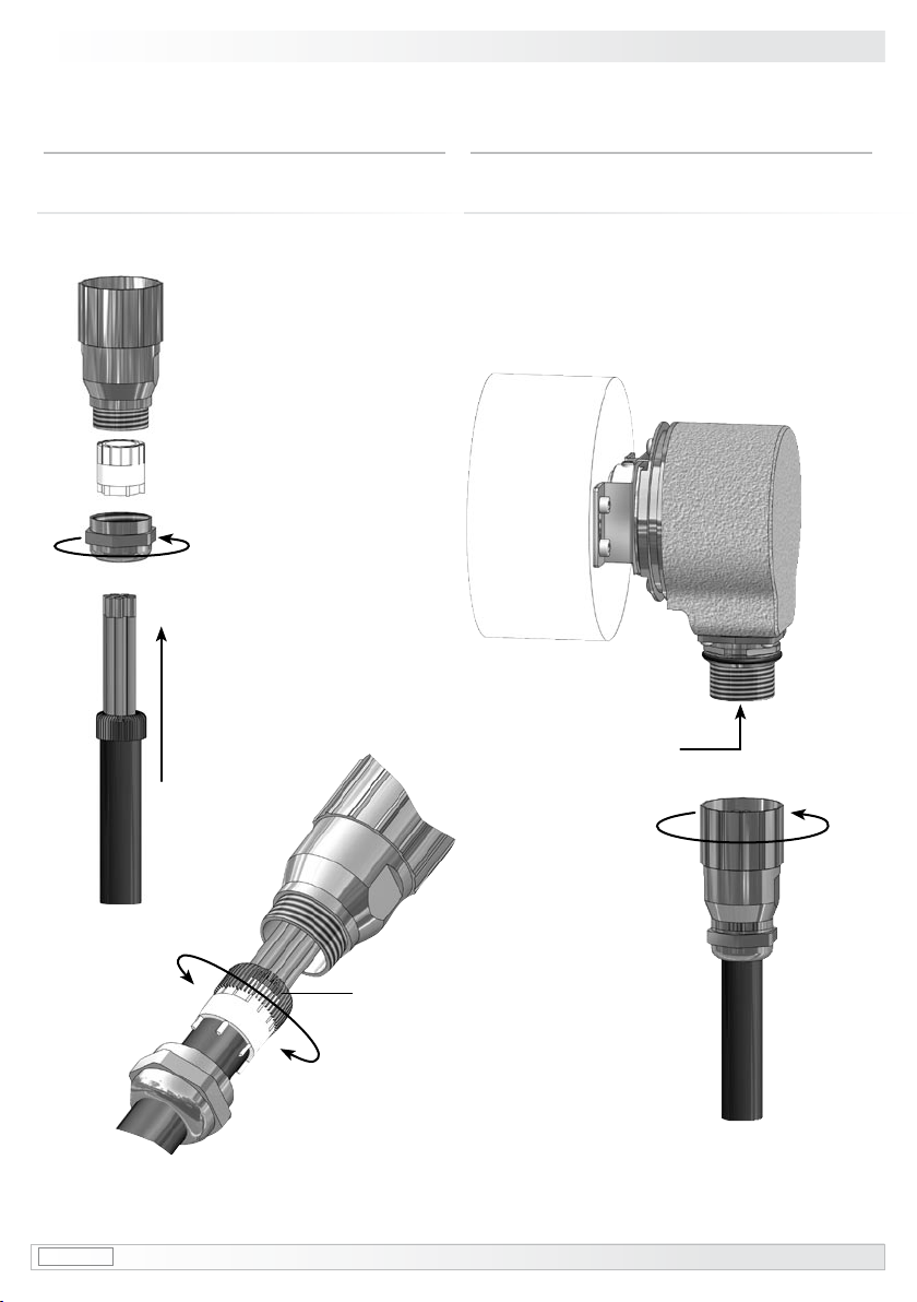
5Montage
5.1 Schritt 1
5Mounting
5.1 Step 1
4.2 zur Montage erforderlich
(nicht im Lieferumfang enthalten) 4.2 required for mounting
(not included in scope of delivery)
10
Anschlusskabel HEK 8
(als Zubehör erhältlich, siehe Abschnitt 7.1.3)
11
4 Schrauben M3 (z. Bsp. DIN ISO 4762)
zur Befestigung des Kupplungsbleches
10
Connecting cable HEK 8
(available as accessory, see section 7.1.3)
11
4 screws M3 (for example DIN ISO 4762)
toxthecouplingplate
10 11
9 hog60_mb (07A2) MB76
5Montage / Mounting
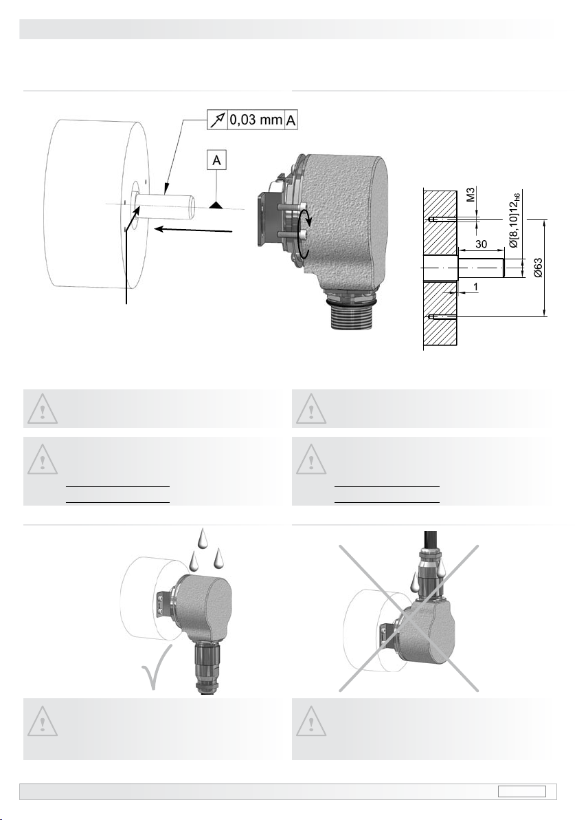
* Sollte die Rundlaufabweichung mehr
als 0,03 mm betragen, so kontaktieren
Sie bitte unsere Hotline:
+49 (0)30/69003-111
* If the radial run-out is more than
0.03 mm, please contact our hotline:
+49 (0)30/69003-111
5.3 Anbauhinweis 5.3 Mounting instruction
Motorwelle einfetten!
Lubricate motor shaft!
Der Einbau des Gebers hat so zu erfol-
gen, dass der Kabelanschluss keinem
direkten Wassereintritt ausgesetzt ist.
The encoder must be mounted in such
a manner that the cable connection is
not directly exposed to water.
5.2 Schritt 2 5.2 Step 2
Ansicht X
View X
Ansicht X
View X
*
All dimensions in millimeters (unless otherwise stated)

MB76 hog60_mb (07A2) 10
Montage / Mounting 5
Auf Bündigkeit zwischen Klemmring
und Hohlwelle achten. Check the ush alignment of the
clamping ring and the hollow shaft.and the hollow shaft.and the hollow shaft..
5.4 Schritt 3 5.4 Step 3
zul. Anzugsmoment:
Max tightening torque:
Mt= 3 Nm
0
0

11 hog60_mb (07A2) MB76
6Maßzeichnung / Dimension drawing
6Maßzeichnung 6Dimension drawing
All dimensions in millimeters (unless otherwise stated)
Option:
Kabelverschraubung mit
Anschlusskabel
Länge wie bestellt
Kabelbelegung siehe Abschnitt 7.2.2
Option:
Screwed gland with
connecting cable
Length as precised on order
Cable assignment see section 7.2.2
Drehrichtung positiv
Positive direction of rotation
MB76 hog60_mb (07A2) 12
Montage / Mounting 5Elektrischer Anschluss / Electrical connection 7
7Elektrischer Anschluss
7.1 Ausführung
mit Flanschdose und Stecker
7.1.1 Kabelanschluss
7Electrical connection
7.1 Version
with ange socket and connector
7.1.1 Cable connection
Ansicht Y
siehe Abschnitt 7.1.2
Viewiew Y
see section 7.1.2
Kabelschirm
Cable shield
13 hog60_mb (07A2) MB76
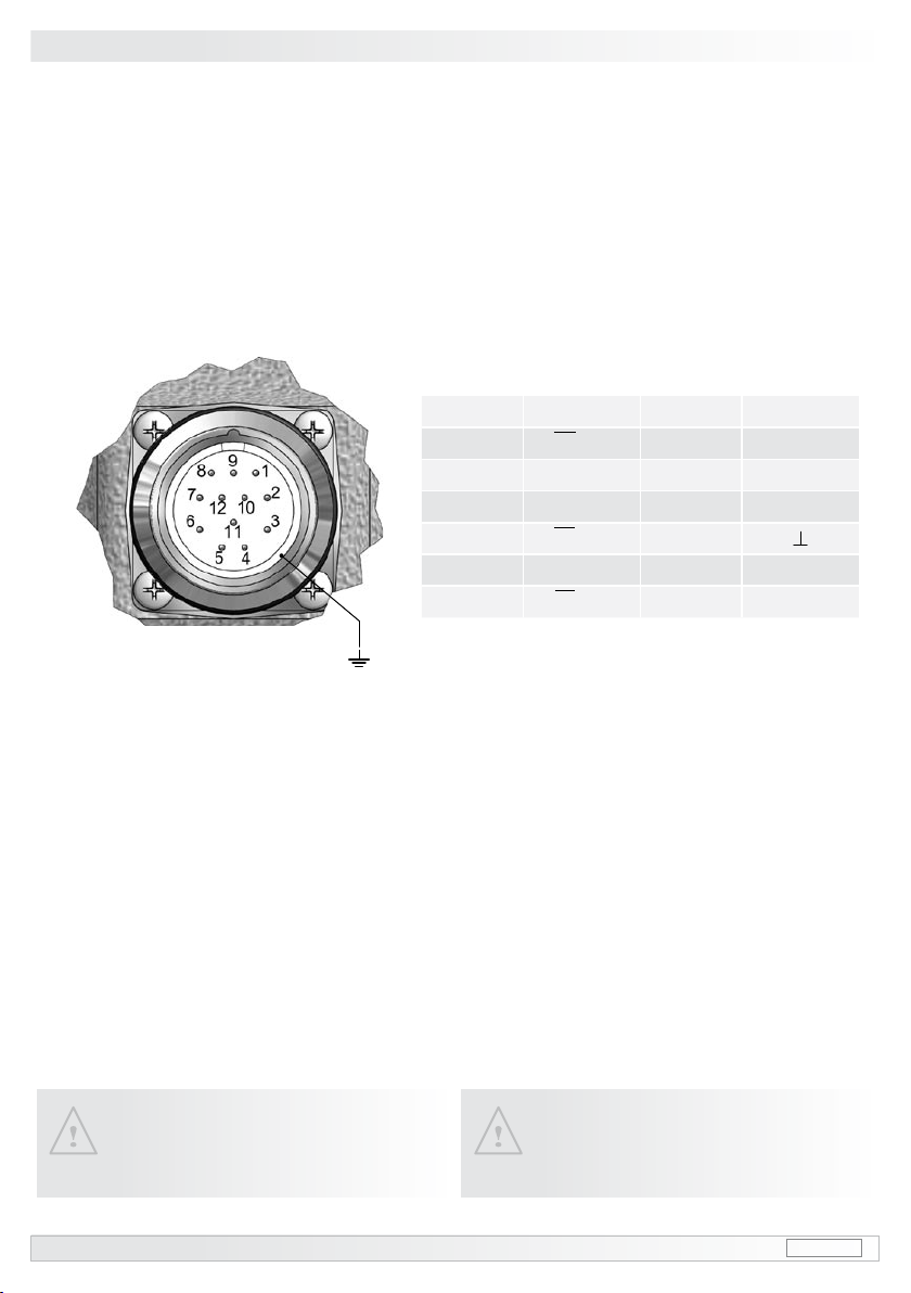
7.1.2 Pinbelegung Flanschdose
HOG 60 DN … CI, DN ... TTL und DN … R
7.1.2 Flange socket pin assignment
HOG 60 DN … CI, DN ... TTL and DN … R… CI, DN ... TTL and DN … R, DN ... TTL and DN … R… RR
7Elektrischer Anschluss / Electrical connection
Pin Signal Pin Signal
1K2 (B-) 7n.c.
2n.c. 8K2 (B+)
3K0 (R+) 9n.c.
4K0 (R-) 10
5K1 (A+) 11 n.c.
6K1 (A-) 12 +UB
Ansicht Y
in Flanschdose 12polig (Stiftkontakte), siehe Abschnitt 7.1.1
View Y
inangesocket12pin(malecontacts),seesection7.1.1
Betriebsspannung nicht aufAusgänge
legen! Zerstörungsgefahr!
Spannungsabfälle in langen Leitungen
berücksichtigen (Ein- und Ausgänge).
Do not connect supply voltage to out-
puts! Danger of damage!
Please, beware of possible voltage drop
in long cable leads (inputs and outputs).

MB76 hog60_mb (07A2) 14
7.1.3 Kabel HEK 8 (Zubehör)
Es wird empfohlen, das Baumer Hübner
Kabel HEK 8 zu verwenden oder ersatz-
weise ein geschirmtes, paarig verseiltes
Kabel. Das Kabel sollte in einem Stück und
getrennt von Motorkabeln verlegt werden.
Kabelabschluss:
Ausführung DN ... CI: 1...3kΩ
Ausführung DN ... TTL und DN ... R:120 Ω
7.1.3 Cable HEK 8 (accessory)
Baumer Hübner cable HEK 8 is recom-
mended. As a substitute a shielded twisted
pair cable can be used. It should have an
uninterrupted run, with ample clearance to
the drive power cable.
Cable terminating resistance:
VersionDN...CI: 1...3kΩ
Version DN ... TTL and DN ... R: 120 Ω
Zur Gewährleistung der angegebenen
Schutzart sind nur geeignete Kabel-
durchmesser zu verwenden.
To ensure the specied protection
class of the device the correct cable
diameter must be used.
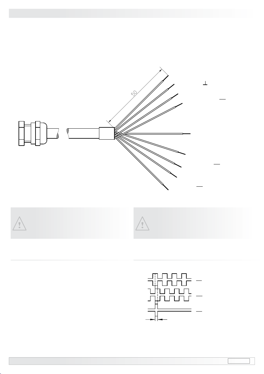
7.1.2 Option: Ausführung
mit Kabelverschraubung und Kabel
7.2.1 Kabelanschluss
7.2 Option: Version
with screwed gland and cable
7.2.1 Cable connection
Anschlusskabel
Länge wie bestellt
Kabelbelegung siehe Abschnitt 7.2.2
Connecting cable
Length as precised on order
Cable assignment see section 7.2.2
Elektrischer Anschluss / Electrical connection 7
Aderendhülsen benutzen.
Use core-end ferrules.
rot/red = +UB
weiß/white = K1 (A+)
braun/brown = K1 (A-)
grün/green = K2 (B+)
grau/grey = K0 (R+)
rosa/pink= K0 (R-)
gelb/yellow = K2 (B-)
Kabelschirm
cable shield
blau/blue = GND
schwarz/black = n.c.
violett/violet = n.c.
15 hog60_mb (07A2) MB76
7Elektrischer Anschluss / Electrical connection
7.2.2 Kabelbelegung
HOG 60 DN … CI, DN ... TTL und DN … R
7.2.2 Cable assignment
HOG 60 DN … CI, DN ... TTL and DN … R… CI, DN ... TTL and DN … R, DN ... TTL and DN … R… RR
Betriebsspannung nicht auf Ausgänge
legen! Zerstörungsgefahr!
Spannungsabfälle in langen Leitungen
berücksichtigen (Ein- und Ausgänge).
Do not connect supply voltage to out-
puts! Danger of damage!
Please, beware of possible voltage drop in
long cable leads (inputs and outputs).
rot/red = +UB
weiß/white = K1 (A+)
braun/brown = K1 (A-)
grün/green = K2 (B+)
grau/grey = K0 (R+)
rosa/pink= K0 (R-)
gelb/yellow = K2 (B-)
blau/blue = GND
schwarz/black =
Schirm/shield
Anschlusskabel
Länge wie bestellt
Connecting cable
Length as precised on order
7.3 Ausgangssignale 7.3 Output signals
1nur bei Ausführung mit invertierten Signalen
only for versions with inverted signals
2nur bei Ausführung mit Nullimpuls
onlyforversionswithmarkerpulse
Signalfolge bei positiver Drehrichtung.
(siehe Abschnitt 6)
Sequence for positive direction of rotation.
(see section 6)
K1
K1 1
K2
K2 1
K02
K01, 2
90°
MB76 hog60_mb (07A2) 16
Demontage / Dismounting 8
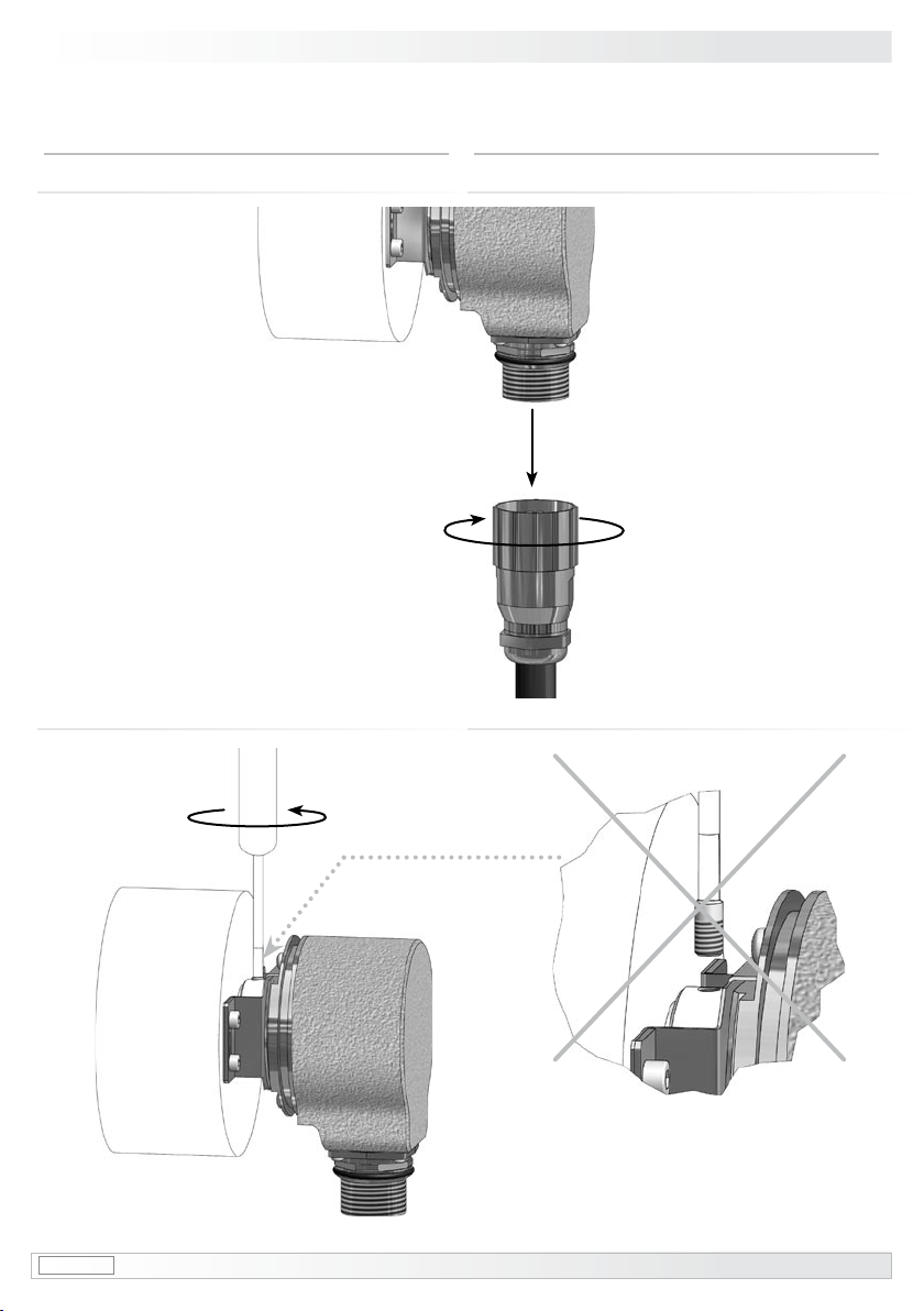
8Demontage
8.1 Schritt 1
8Dismounting
8.1 Step 1
8.2 Schritt 2 8.2 Step 2
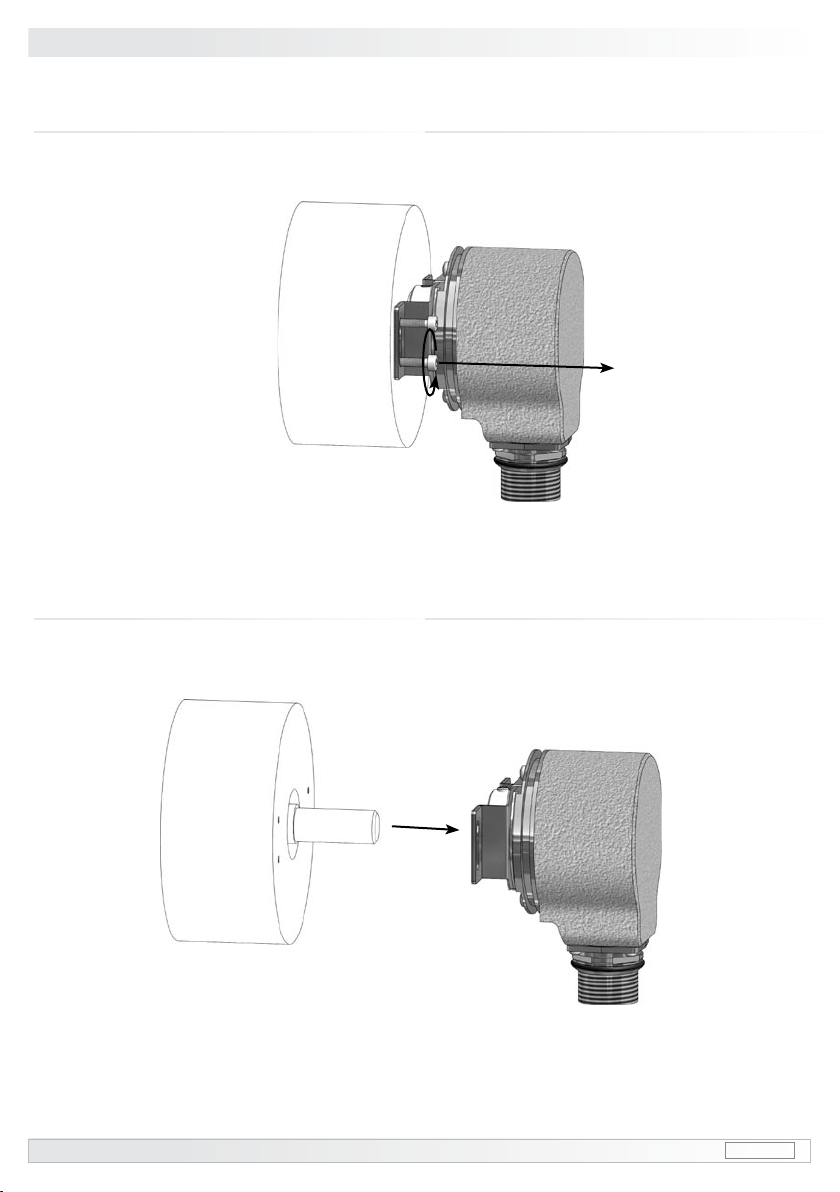
17 hog60_mb (07A2) MB76
8Demontage / Dismounting
8.4 Schritt 4 8.4 Step 4
8.3 Schritt 3 8.3 Step 3
Table of contents
Other Baumer Hübner Media Converter manuals

Baumer Hübner
Baumer Hübner HMG 161 Service manual

Baumer Hübner
Baumer Hübner HOG 10 Owner's manual

Baumer Hübner
Baumer Hübner POG 10 Service manual

Baumer Hübner
Baumer Hübner HOGS 100 S Service manual

Baumer Hübner
Baumer Hübner HOG 11 Series User manual

Baumer Hübner
Baumer Hübner OG9 Service manual

Baumer Hübner
Baumer Hübner HOG 75 Service manual

Baumer Hübner
Baumer Hübner HMG 11 + FSL User manual

Baumer Hübner
Baumer Hübner POG 90 User manual


