MB110 - 11055720 Baumer_TDP009-TDPZ009_II_DE-EN (19A2)
Montage / Mounting 4Table of contents
Table of contents
1General notes ................................................................................................................................................................2
2Security indications ..................................................................................................................................................4
3Preparation .....................................................................................................................................................................5
3.1 Scope of delivery ............................................................................................................................................5
3.2 Required for mounting (not included in scope of delivery) .......................................................6
3.3 Required tools (not included in scope of delivery) ........................................................................ 6
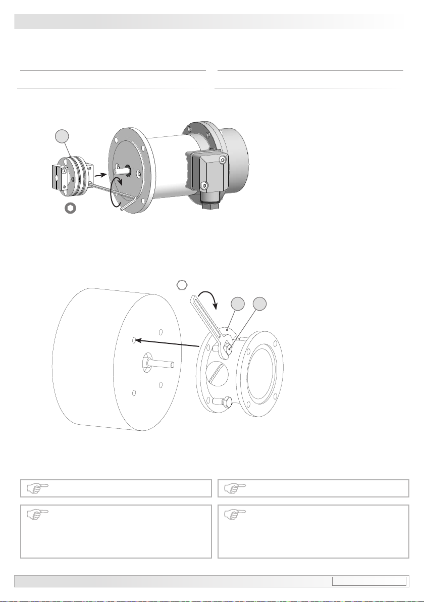
4Mounting ...........................................................................................................................................................................7
4.1 Withange............................................................................................................................................................7
4.1.1 Step 1 ................................................................................................................................................................ 7
4.1.2 Step 2 ................................................................................................................................................................7
4.1.3 Step 3 ................................................................................................................................................................8
4.1.4 Step 4 ................................................................................................................................................................8
4.2 Option B3: Housing foot ..............................................................................................................................8
4.2.1 Step 1 ................................................................................................................................................................8
4.2.2 Step 2 ................................................................................................................................................................9
4.2.3 Step 3 ................................................................................................................................................................9
5Dimensions .................................................................................................................................................................. 10
5.1 Withange...................................................................................................................................................... 10
5.1.1 Standard.......................................................................................................................................................... 10
5.1.2 Option Z: TDPZ 0,09................................................................................................................................. 10
5.2 Option B3: Housing foot ............................................................................................................................11
6Mounting instructions ...........................................................................................................................................11
6.1 Avoiding water entry ...................................................................................................................................11
6.2 Maximum permissible mounting tolerance when the
Baumer Hübner K 35 spring disk coupling is used .................................................................... 12
6.3 Note when using a jaw-type coupling (for example “ROTEX®”) ........................................ 13
7Electrical connection ............................................................................................................................................ 14
7.1 Cable connection ......................................................................................................................................... 14
7.2 Connecting terminal ................................................................................................................................... 14
8Operation and maintenance ............................................................................................................................. 15
8.1 Replace of the carbon brushes ............................................................................................................ 15
9Dismounting ................................................................................................................................................................ 16
9.1 Disconnect electrical connection ........................................................................................................ 16
9.2 Withange...................................................................................................................................................... 17
9.3 Option B3: Housing foot ........................................................................................................................... 18
10 Technical data ............................................................................................................................................................ 21
10.1 Technical data - electrical ratings ....................................................................................................... 21
10.2 Technical data - mechanical design .................................................................................................. 21
10.3 Type data ......................................................................................................................................................... 22
10.4 Replacement switching diagram ......................................................................................................... 22
11 Accessories ................................................................................................................................................................. 23