MB043 - 11055646 Baumer_TDP009-FSL_II_DE-EN (19A1)
Table of contents
Table of contents
1General notes ................................................................................................................................................................2
2Security indications ..................................................................................................................................................4
3Preparation .....................................................................................................................................................................5
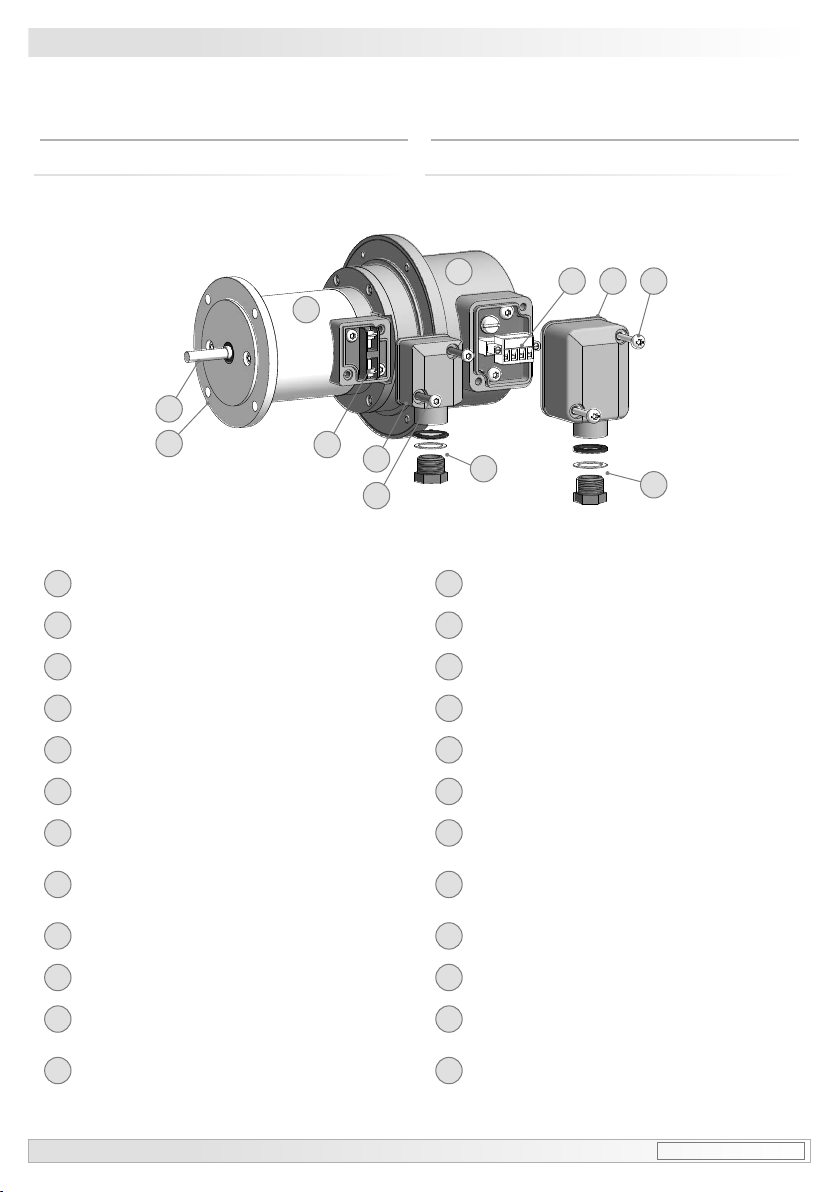
3.1 Scope of delivery ............................................................................................................................................5
3.2 Required for mounting (not included in scope of delivery) ....................................................... 6
3.3 Required tools (not included in scope of delivery) ........................................................................6
4Mounting ...........................................................................................................................................................................7
4.1 Step 1 ...................................................................................................................................................................7
4.2 Step 2 ...................................................................................................................................................................7
4.3 Step 3 ...................................................................................................................................................................8
4.4 Step 4 ...................................................................................................................................................................8
4.5 Maximum permissible mounting tolerance when the
Baumer Hübner K 35 spring disk coupling is used ....................................................................... 9
4.6 Mounting instruction .................................................................................................................................. 10
5Dimension ..................................................................................................................................................................... 10
6Electrical connection .............................................................................................................................................11
6.1 TDP 0,09 ...........................................................................................................................................................11
6.1.1 Cable connection ......................................................................................................................................11
6.1.2 Connecting terminal ................................................................................................................................11
6.2 FSL ...................................................................................................................................................................... 12
6.2.1 Cable connection ..................................................................................................................................... 12
6.2.2 Connecting terminal ............................................................................................................................... 12
7Operation and maintenance ............................................................................................................................. 13
7.1 Replace of the carbon brushes ............................................................................................................ 13
8Dismounting ................................................................................................................................................................ 14
8.1 Step 1 ................................................................................................................................................................ 14
8.2 Step 2 ................................................................................................................................................................ 14
8.3 Step 3 ................................................................................................................................................................ 15
8.4 Step 4 ................................................................................................................................................................ 15
8.5 Step 5 ................................................................................................................................................................ 15
9Accessories ................................................................................................................................................................. 16
10 Technical data ............................................................................................................................................................ 19
10.1 Technical data - electrical ratings ....................................................................................................... 19
10.2 Technical data - electrical ratings (tachogenerator) .................................................................. 19
10.3 Technical data - electrical ratings (centrifugal switch) ............................................................. 19
10.4 Technical data - mechanical design .................................................................................................. 19
10.5 Test conditions for switching speed ................................................................................................... 20
10.6 Type data ......................................................................................................................................................... 20
10.7 Replacement switching diagram ......................................................................................................... 20