BAUMOT BA5000 User manual

Operating Manual
DPF Cleaning System
I innovative exhaust aftertreatment

2
02/11/2010 Germany: +49 (0)2361 / 30 231 – 0; Switzerland: +41 (0)44 / 954 80 7 - 0
Table of contents
1. Information for Customers………………………………………………………………………………………….. 3
1.1. General Information………………………………………………………………………………………………... 3
1.2. Guarantee and Liability……………………………………………………………………………………………. 3
1.3. Symbols Used………………………………………………………………………………………………………. 3
2. Safety Information…………………………………………………………………………………………………….. 4
2.1. General Safety Instructions……………………………………………………………………………………….. 4
2.1.1. Safety Instructions for Operation……………………………………………………………………………….. 4
2.1.2. Safety Check Before Start-up…………………………………………………………………………………... 5
2.1.3. Safety Instructions for Maintenance and Repair……………………………………………………………… 5
2.2. Safety and Protective Equipment, Excerpt from the Danger Assessment…………………………………... 5
2.3. Installation and Assembly…………………………………………………………………………………………. 5
3. Technical Data…………………………………………………………………………………………………………. 6
4. General Description…………………………………………………………………………………………………... 6
4.1. Intended Use……………………………………………………………………………………………………….. 6
4.2. Assembly Procedure (Short Description)………………………………………………………………………... 6
5. Description of Machine Components……………………………………………………………………………... 7
5.1. Machine Overview…………………………………………………………………………………………………. 7
5.2. Overview of Safety Devices…………………………………………………………………………….………… 7
5.3. Control………………………………………………………………………………………………………………. 8
5.4. Electric Field Sensors……………………………………………………………………………………………… 8
5.5. Operator’s Console………………………………………………………………………………………………… 8
5.6. Cleaning Chamber…………………………………………………………………………………………………. 8
5.7. Cleaning Apparatus………………………………………………………………………………………………... 9
5.8. Adapter Ring Insertion…………………………………………………………………………………………….. 9
5.9. Start-up……………………………………………………………………………………………………………… 9
5.9.1. First Steps………………………………………………………………………………………………………… 9
5.9.2. EMERGENCY STOP Acknowledgement…………………………………………………............................ 9
5.9.3. Suction Start-up………………………………………………………………………………………………….. 9
5.9.4. Inserting Filters…………………………………………………………………………………………………. 10
5.9.5. Switching on Automatic Operation …………………………………………………………………………… 10
5.9.6. Premature Shut-off of Automatic Operation…………………………………………………………………. 10
5.9.7. Removing Filters……………………………………………………………………………………………...... 10
5.9.8. Setup instructions for pressure switch…………………………………………..………………………….... 11
5.9.9 Setting the pressure switch…………………………………………………………………………………….. 11
6. Malfunction Description……………………………………………………………………………………………. 12
7. Service…………………………………………………………………………………………………………………. 12
7.1. Maintenance and Lubrication Instructions……………………………………………………………………... 12
8. Disposal……………………………………………………………………………………………………………….. 13
Addresses………………………………………………………………………………………………………………... 14

3
02/11/2010 Germany: +49 (0)2361 / 30 231 – 0; Switzerland: +41 (0)44 / 954 80 7 - 0
1. Information for Customers
1.1 General Information
This operator’s manual is part of the user information when the machine is brought into circulation. It describes
the setup, operation and basic maintenance procedure of the machine mentioned above.
It must be kept such that it is accessible to the operator and users in a readable format at any time. When the
machine is moved to a different location, the operating manual must accompany it as it is part of the machine.
The operating manual contains important information on how to operate the machine safely, correctly, and
efficiently. Observing the manual helps to prevent dangers, avoid repair costs and down time, and increases the
reliability and service life of the machine.
The entire operating manual must be read and applied by everyone who is instructed to work with the machine.
The machine may only be switched on and operated by trained and responsible operating personnel.
The operator of the machine must make the user manual accessible to users and make sure that they have read
and understood it. Only then may the machine be put into operation.
The operator is required to observe all operating and safety instructions given in this operating manual as well as
all such legal instructions.
The respective operating manual of any devices and equipment purchased from the manufacturer of the machine
must be observed.
1.2 Guarantee and Liability
The general guarantee and liability for this machine is 24 months for single-shift operation. Parts that
are subject to wear are excluded. The guarantee of the supplier applies to purchased parts.
The guarantee and liability in the event of bodily injury and property damage are excluded if they are attributable
to the following causes:
Improper use of the machine
Improper operation and maintenance of the machine
Operating the machine with defective, improperly installed, or non-functional safety and protective
equipment
Operating the machine with defective or not completely functional parts and assemblies
Non-observance of the operating manual in all details
Unauthorized structural changes or changes to the performance data
Improperly executed repairs
Force majeure
Interventions and changes to the machine and machine systems that are not authorized by us, in particular to
electrical, mechanical, hydraulic and pneumatic components may result in the cancellation of the declaration of
conformity and loss of the CE mark.
1.3 Symbols Used
Warning of danger
Warning of danger of crushing

4
02/11/2010 Germany: +49 (0)2361 / 30 231 – 0; Switzerland: +41 (0)44 / 954 80 7 - 0
Wear protective mask
Observe instructions unconditionally
Open flame of any type and smoking forbidden
Do not eat near the machine
Maintenance
Manual cleaning
2. Safety Information
2.1 General Safety Instructions
Read the operating manual carefully before starting up the machine!
Independent of the description in this operating manual, safety and accident prevention regulations apply to the
operation of the machine.
The respective safety instructions of any devices and equipment purchased from the manufacturer of the
machine must be observed.
The existence and operation of protective equipment must be checked before production begins.
Safety and protective equipment may not be removed or disabled. In the event of malfunctions or faults in the
machine that have an adverse effect on safety, they must be eliminated immediately.
This machine may only be used by employees who have been instructed to do so by their supervisors and are
familiar with its operation.
Responsibilities must be clearly established and defined. Observe the statutory minimum age!
2.1.1 Safety Instructions for Operation
For reasons of safety, we point out in particular observance of the points given in the following.
The machine may not be used to clean any filters that contain explosive, combustible and oily dusts,
dust/air mixtures and hybrid mixtures.
The machine must have an explosion protected design for explosive dust-air mixtures. There are special
regulations for this.
In order to keep the danger to persons and the machine to a minimum, it is not permitted
to work with hot objects, use open flames of any type or to smoke in the cleaning
chamber and in the area around the machine.
The operating temperature as well as the filter temperature must not exceed 70°C when inserting a filter.
Eating close to the machine is also not permitted.

5
02/11/2010 Germany: +49 (0)2361 / 30 231 – 0; Switzerland: +41 (0)44 / 954 80 7 - 0
2.1.2 Safety Check Before Start-up
The following safety checks must be performed before operating the machine:
Check the side panels and covers to make sure they are in place and tight.
Check the protective doors to make sure they work and seal when closed. The doors must be opened for
this. Now, it must not be possible to switch on the machine.
Check the emergency stop apparatus by pressing the emergency stop switch and opening the protective
doors. Here, the voltage and the air to the machine must be cut off. It is only possible to start up again
after the emergency connection is acknowledged.
The suction system must be connected. Please make sure that the suction hose is attached to the
machine.
The machine may only be operated with the suction system switched on.
Remove all filters and items from the machine.
2.1.3 Safety Instructions for Maintenance and Repair
Before starting service or maintenance work, shut off the power supply to the machine. The power and
air can be cut off by unplugging the power and air connecting line.
Only qualified technicians may perform work on electric machines and devices that are under voltage. (See DIN
VDE 0105 or IEC 364)
Please note: It is necessary to wear protective masks when cleaning the machine.
2.2 Safety and Protective Equipment, Excerpt from the Danger Assessment
Besides general and mechanical components, a dangerous part of the machine is the automatic cleaning of the
filter.
To reduce the danger, the machine has been encapsulated and equipped with monitored protective doors at the
access points.
Emergency stop switches have been installed for fast and safe shutdown of the machine components in a
dangerous situation.
2.3 Installation and Assembly
The machine is a mobile utensil that is mounted on rollers. As a result, it is possible to adapt the device
optimally to the work area by pushing it there.
It is also possible to transport the machine with the help of a pallet lifter or stacker. Here, make sure that there is
enough support area on the forks under the device’s traverse.
Please note: There is a danger of tipping when pushing and transporting the machine.
The setup site must be sufficiently firm, horizontal and dry.
The surrounding temperature must not deviate from the temperature given in the technical data.
The machine is connected to the utilities network by means of the device’s plug connector for power and a quick-
release coupling for the air.
Independent of this description, installation manuals of the manufacturers of purchased parts must be observed.
(See suction description.)
6
02/11/2010 Germany: +49 (0)2361 / 30 231 – 0; Switzerland: +41 (0)44 / 954 80 7 - 0
3. Technical Data
Machine number:
Year of construction:…………………. 2010
Net weight:……………………………... 120 kg
Machine dimensions:
Depth…………………………………….700 mm
Width……………………………………. 1160 mm
Height:………………………………….. 1890 mm
Operating pressure:…………………… 6 bar
Voltage:………………………………….230V
Frequency:……………………………... 50 Hz
Series fuse:…………………………….. 16A
Power consumption:………………….. 200 W
Control voltage:………………………... 24V / DC
Auxiliary power:………………………...air 6 bar, dehumidified not oiled, humidity level > 1%, constant air
pressure, Connector: NW 7.2 nipple plug-in
Ambient temperature:………………….0 – 35° C
Cabinet temperature:…………………..0 – 35° C
Operating noise:………………………..> 75 db
Note: The machine pressure must be 6 bar. If there is not enough air pressure, the machine may have
operating problems.
4. General Description
Machine description
4.1 Intended Use
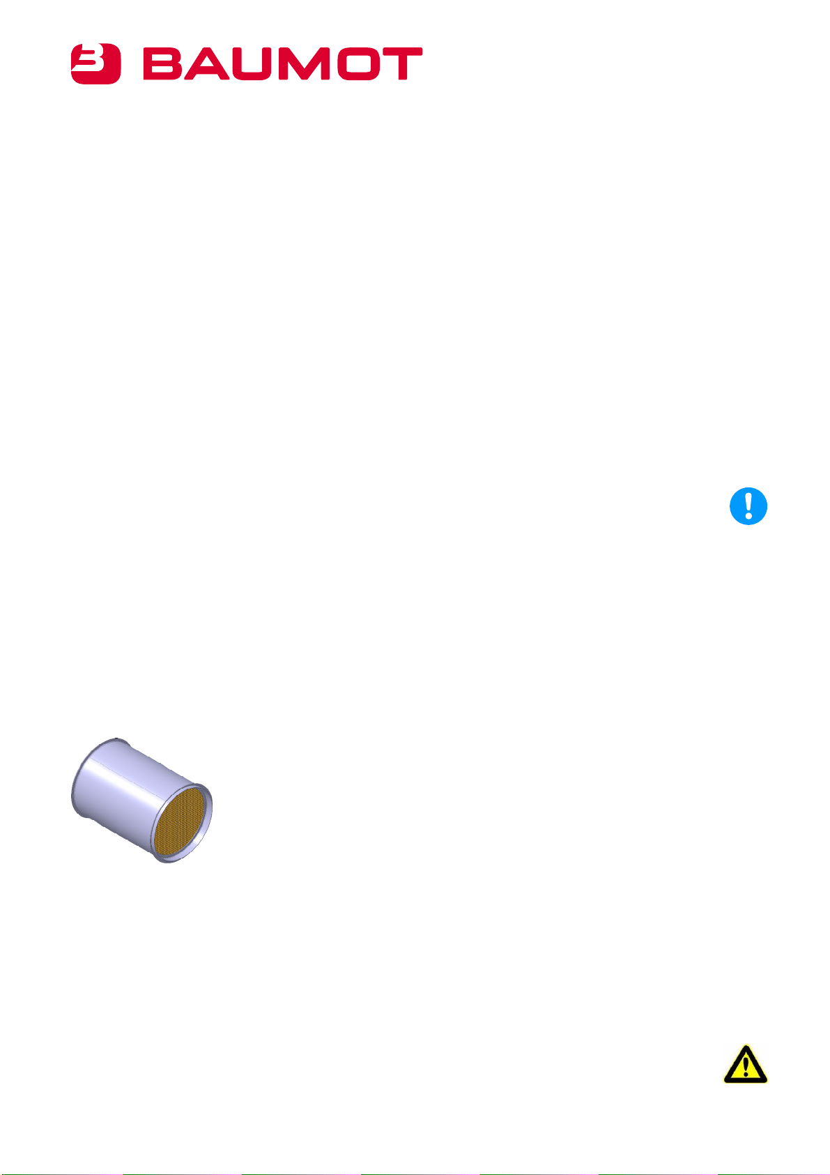
The design of the unit is based on the Baumot filter design. However, it can also clean filters from almost all other
manufacturers.
Below is an example of the filter that is blown out in the cleaning system.
Observation of this operating manual is also part of proper use.
It is not permitted to use any type of cleaning agents.
4.2 Assembly Procedure (Short Description)
The machine consists of the machine body with the cleaning chamber, the automatic cleaner, the swiveling
device as well as the protective covers and protective doors. There is also an industrial vacuum cleaner on the
side.
(The industrial vacuum cleaner is not part of the machine.)
Please note: It is absolutely mandatory to extract the filter particles with the help of an industrial
vacuum cleaner during the cleaning process.

7
02/11/2010 Germany: +49 (0)2361 / 30 231 – 0; Switzerland: +41 (0)44 / 954 80 7 - 0
Procedure
First of all, the suction is switched on. Then, the filter insert is placed in the correct position in the cleaning
chamber by opening the protective doors. The emergency stop device is acknowledged using the "Reset"
button. Afterwards, the machine can be switched on using the “Start” button.
The “ ” light indicates that the machine is in operation.
The cleaning process stops when the “Stop” button is pressed or the cleaning time has ended. The filter
can be removed from the machine.
5. Description of Machine Components
5.1 Machine Overview
5.2 Overview of Safety Devices
Machine housing
Operator’s console
Adapter rings
Cleaning chamber
Emergency stop
Suction connector
Area for suction system
Rollers
Protective doors
Protective doors
Door safety switch
8
02/11/2010 Germany: +49 (0)2361 / 30 231 – 0; Switzerland: +41 (0)44 / 954 80 7 - 0
1
2
3
5.3 Control
Main equipment cabinet
One part of the control elements for the machine process is located in the lower section of the cleaning
machine. The fuses, motor protection, PLC controller, protection for motors, clamps and safety relays
are here.
5.4 Electric Field Sensors
All the machine’s sensors such as the limit switch, buttons and safety relays, for example, are connected to the
PLC controller. The switching statuses of the sensors are shown on the sensors or the PLC.
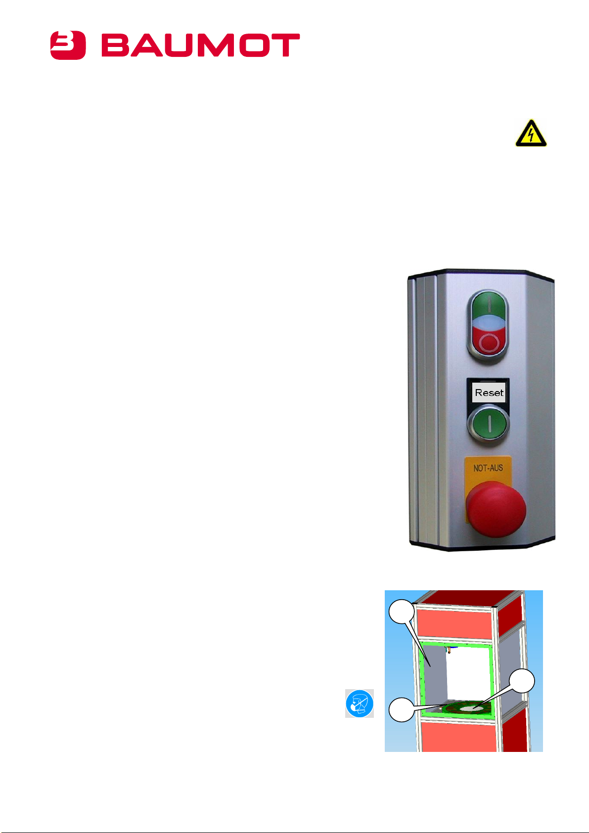
5.5 Operator’s Console
The machine’s operator’s console fulfils the following functions:
1) Button/lamp combination
The machine is switched on and off with this.
Among other things, the integrated signal light (white field) indicates the
following:
Solid light – machine is running without any problems
Flashing – Machine malfunction
The lamp flashes if the emergency stop relay has been triggered and the
“On” switch is pressed at the same time.
2) Emergency stop reset switch
The emergency stop reset switch is used to acknowledge the emergency off
relay after it has been triggered.
3) Emergency stop switch
The emergency stop switch can be used to stop dangerous movements in
the event of danger.
Please note: The cylinder may still be under pressure even if the emergency
stop button has been pressed. The emergency stop switch is not a repair
switch!!!
5.6 Cleaning Chamber
The filter chamber consists of a closed stainless steel container (1) that
forms a tight seal with the protective doors.
The slewing ring (2) with the extraction funnel (3) are located in the base
area.
The chamber and the slewing ring must be cleaned occasionally. This
can be done with the industrial vacuum cleaner.
Please note: A protective mask must be worn while cleaning.
If cleaning cloths are used, then they must be disposed of properly after
cleaning.
2
3
1
9
02/11/2010 Germany: +49 (0)2361 / 30 231 – 0; Switzerland: +41 (0)44 / 954 80 7 - 0
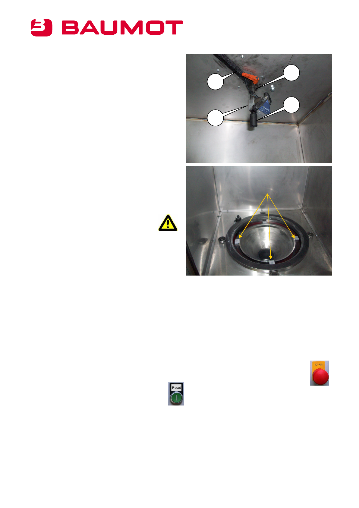
5.7 Cleaning Apparatus
The cleaning apparatus is needed for blowing out the
filter. The apparatus consists of the oscillator rod with
the drive cylinder, the clamping unit for the nozzle rod
(1) as well as the limit switch for the oscillation (2).
The cleaning nozzle (3) is located on the cleaning rod.
The brush (4) prevents dust from escaping from the
cleaning chamber. It must be replaced when necessary.
5.8 Adapter Ring Insertion
The adapter rings are used to compensate for the
different filter diameters above the suction funnel.
Here, the adapter ring must be inserted flush into the
slew ring from above (arrow). The adapter ring must
seal evenly with the slewing ring.
Please note: An incorrectly inserted adapter
ring can lead to damage to the cleaning
apparatus.
5.9 Start-up
5.9.1 First Steps
Install the matching adapter rings.
Connect the device’s plug connector and air connector. (check air pressure)
Plug in the industrial vacuum cleaner and mount the suction hose.
Remove all objects or parts from the machine.
Perform a functional test of all safety devices.
5.9.2 Emergency Stop Acknowledgement
Close the protective doors and release the emergency stop switch by pulling out the
emergency off button.
Press the “Reset” button on the operator’s console.
5.9.3 Suction Start-up
Insert the suction unit into the “suction connector” on the cleaning unit.
Insert the suction tube into the suction supports on the cleaning unit.
Switch on the suction unit (see suction unit operator's manual).
4
1
2
3
10
02/11/2010 Germany: +49 (0)2361 / 30 231 – 0; Switzerland: +41 (0)44 / 954 80 7 - 0
1
3
2
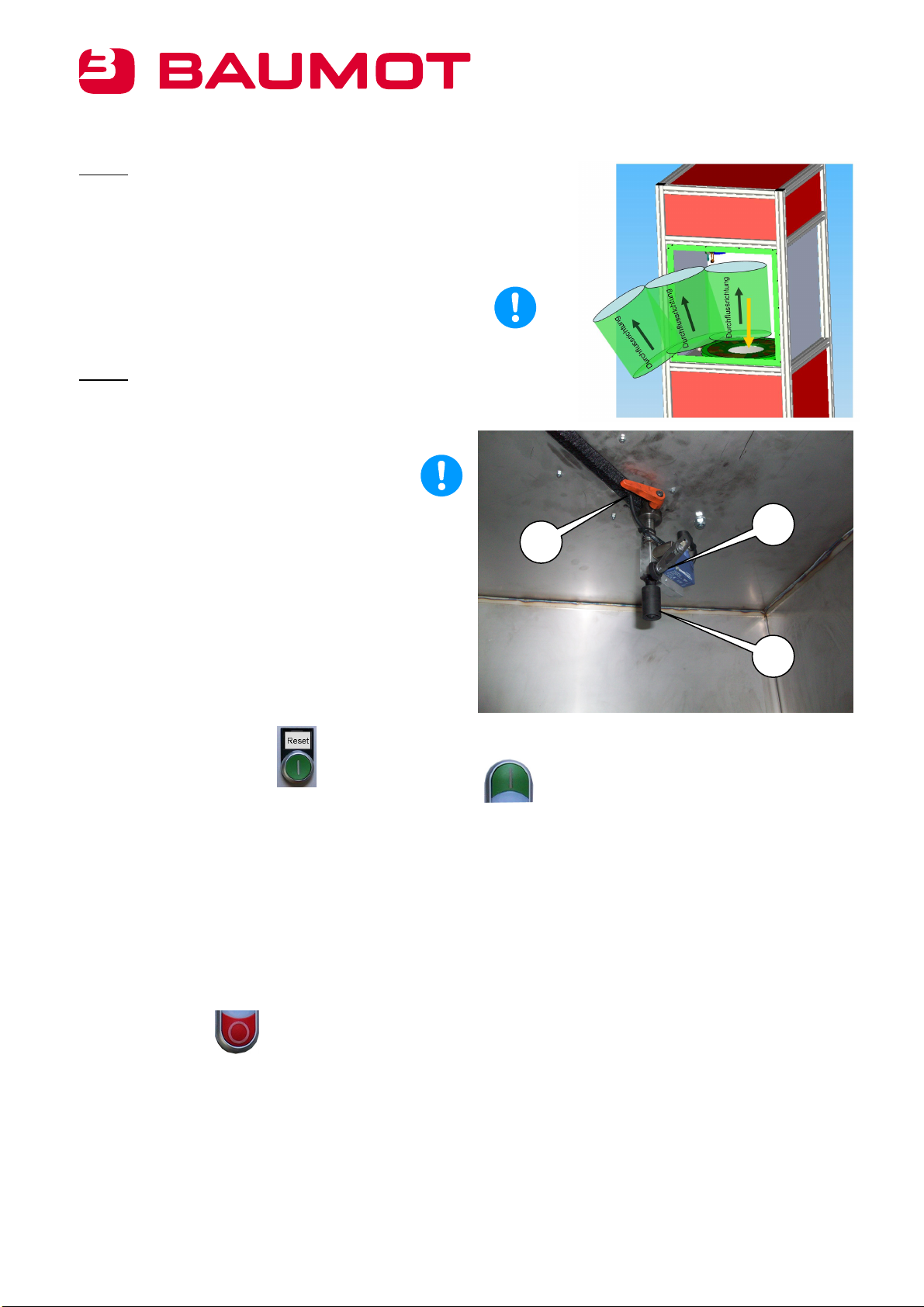
5.9.4 Inserting Filters
Step 1: Insert the filter
After opening the machine’s door, the filter must be
placed on the adapter ring in the correct position.
To do this, it is placed on the adapter ring from the top
(yellow arrow) such that its edge encloses the edge of
the funnel area.
Please note: The filter must be inserted opposite to its
direction of flow.
Step 2: Setting the cleaning nozzle
The nozzle rod locking device (1) must be disengaged
to adjust the cleaning nozzle, and the cleaning nozzle
(2) lowered to the top filter rim.
Please note: The nozzle head must not touch
the rim.
The actuating roller of the limit switch for the oscillation
(3) is actuated by the filter rim and that way limits the
oscillation path of the cleaning nozzle. The oscillation
path is limited by the drive cylinder for a filter without a
filter rim.
5.9.5 Switching on Automatic Operation
Close the protective doors.
Acknowledge the emergency stop switch using
the “Reset” button.
Press the “Start” button on the operator’s console.
The control lamp on the operator’s console starts to illuminate. The cleaning nozzle is pressurized with air and
the oscillation starts.
Automatic operation switches off after 30 minutes. The protective doors can be opened and the filter removed.
It is possible to restart the machine immediately.
5.9.6 Premature Shut-off of Automatic Operation
The “Stop” button can be used at any time to stop automatic operation. Automatic operation is switched off by
pressing the “Stop” button. The process time is reset.
5.9.7 Removing Filters
The filter is removed in the reverse order to inserting it.
Disengage the nozzle rod locking device.
Raise the cleaning nozzle.
Remove the filter.
11
02/11/2010 Germany: +49 (0)2361 / 30 231 – 0; Switzerland: +41 (0)44 / 954 80 7 - 0
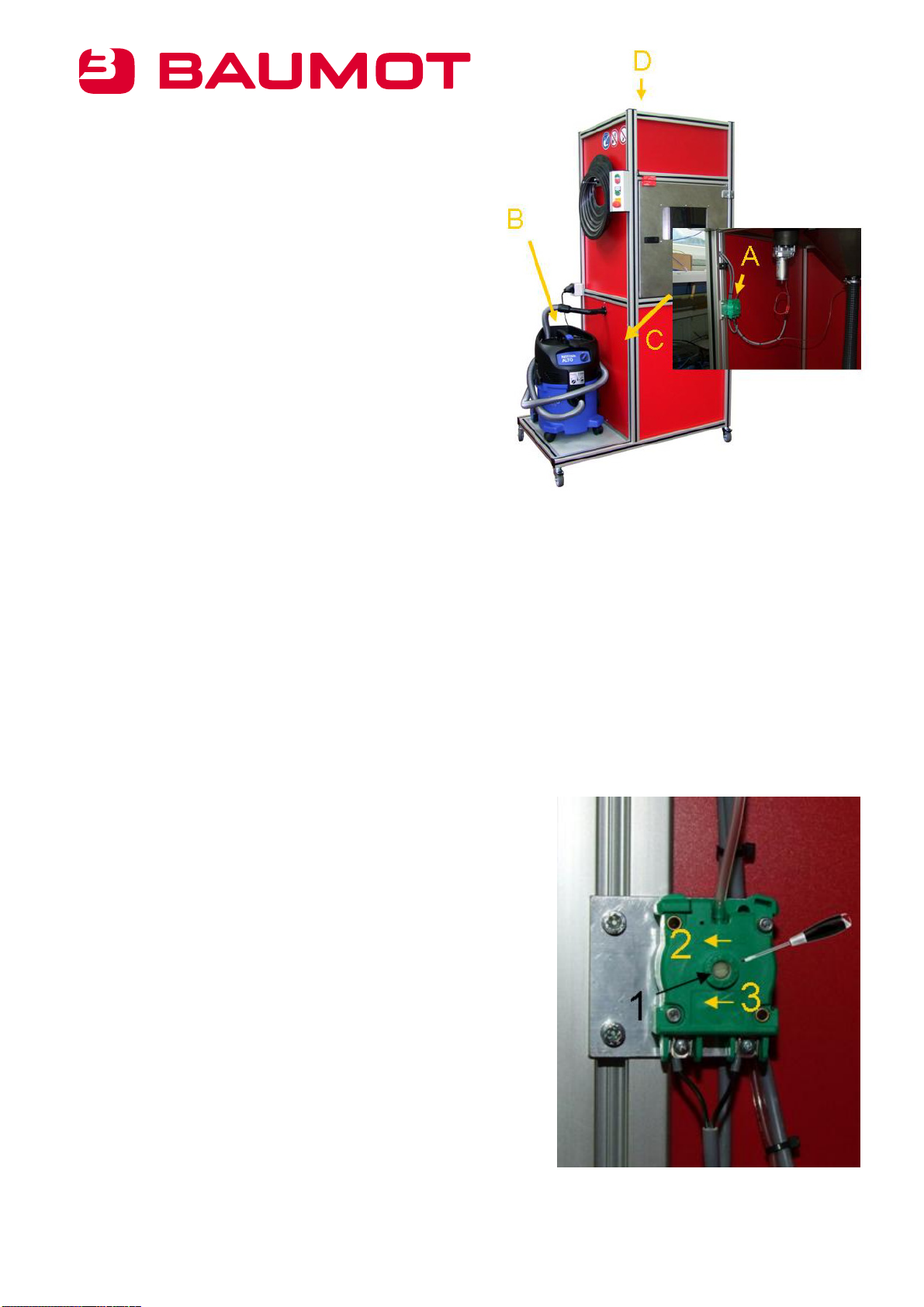
5.9.8 Setup instructions for pressure wave switch DW
3 S-100, type AL2-14, MR-D Industriegeräte GmbH
The BA 5000 cleaning unit is equipped with a DW 3S-100
pressure wave switch (A). The pressure wave switch is
used to monitor the exhaust air of the connected industrial
vacuum cleaner (B). It is located behind panel (C) in the
unit.
The signals of the pressure wave switch are evaluated by
the PLC control. If the suction performance (negative
pressure) is too low, the signal on input 7 of the PLC control
drops.
The unit switches off after a monitoring period. This
malfunction can be confirmed only by restarting the unit.
5.9.9 Setting the pressure switch
Preparation
Pull the plug of the industrial vacuum cleaner out of the outlet on the cleaning device and plug it into an
external outlet. (Keep the vacuum cleaner off.)
Open the top cover of the cleaning device (D); this is where the PLC control is located.
Connect the cleaning device to the external power supply (the PLC is supplied with power).
Open the cover (C) to access the pressure switch (A).
Setting the pressure switch
Insert the screwdriver into the plastic setting screw (1) and
turn it anticlockwise until it stops (2).
Switch the industrial vacuum cleaner on.
Caution:
The industrial vacuum cleaner’s filter insert must be clean; a filter
must not be in the unit.
Turn the plastic setting screw slowly clockwise until input 7
on the PLC lights up.
Continue to turn the screw until you have attained the
desired setting range (~ 5 division marks).
Switch the industrial vacuum cleaner off. Input 7 on the
PLC goes out.
The adjustment of the pressure switch is complete. The covers can
be reattached.
12
02/11/2010 Germany: +49 (0)2361 / 30 231 – 0; Switzerland: +41 (0)44 / 954 80 7 - 0
6. Malfunction Description
Malfunction Possible cause Remedial measures
System has no voltage
Connection line not
plugged in
Fuse has tripped
Plug in the connection line
Inform an electrician
System cannot be acknowledged Emergency stop pressed
Doors not closed
Check emergency off and
door switches
Cleaning result is not
adequate
Air pressure too low
Blowing nozzle clogged
Nozzle not set low enough
Check air pressure
Clean blowing nozzle
Check nozzle setting
Filter particles are escaping
Cleaning apparatus sealing
brushes leaky
Door seal faulty
Clean or replace the
sealing brushes
Check door seal
Slewing ring does not turn Motor fuse tripped
Slewing ring stuck
Inform an electrician
Check slewing ring
mechanics
Cleaning apparatus does not
oscillate
Air pressure too low
Swiveling cylinder faulty or
stuck
Check air pressure
Check swiveling cylinder
Please note: The cylinder
may be
under pressure. Danger
of crushing.
No, or too little,
suction
Suction turned off or faulty
Filter clogged
Suction tube leaky
Wrong adapter rings
installed
Check suction system
Clean filter
Check suction tubes
Check adapter rings
7. Service
7.1 Maintenance and Lubrication Instructions
The maintenance and lubrication instructions here do not replace the specifications of the manufacturer
in the respective operating instructions.
Defective parts must be replaced without delay.
The machine should be cleaned with an industrial vacuum cleaner or a cloth.
Do not use compressed air!!!
Switch off the power supplies before maintenance. To do this, the power and air lines must be separated from
the utility network.
13
02/11/2010 Germany: +49 (0)2361 / 30 231 – 0; Switzerland: +41 (0)44 / 954 80 7 - 0
Maintenance plan: Table 1
Name Task Time period
Machine
Machine body Cleaning and inspection Every shift
Construction Tighten the screw connections ¼ yearly
Rotating mechanism with
slewing ring Clean Daily
Cleaning apparatus Clean Weekly
Oscillator seal Clean As required
The bearings and cylinder are maintenance-free.
8. Disposal
Please note: Separate the machine from the power and air network before disposal.
Disassembly procedure:
Remove the power and air lines.
Professionally remove the operating supplies.
Disassemble the machine.
Take the plastic parts to plastic recycling.
Take the metal parts to metal recycling.
Take the electronic assemblies and connection lines to special waste or to electronics waste.

I innovative exhaust aftertreatment
Contact
Netherlands
Baumot Nederland BV
Aarplein 24
NL-2406 BZ Alphen aan den Rijn
Tel.: +31 (0) 6 555 127 80
Fax: +31 (0) 172 493 109
Denmark / Sweden
Norway / Finland / Iceland
Baumot Nordic Apsv
Motorgangen 13
DK-2690 Karlslunde
Tel.: +45 46 40 03 00
Fax: +45 46 40 03 08
Italy
Baumot Italien S.r.l.
Via Del Tecchione, 24/B
I-20098 San Giuliano Milanese (MI)
Tel.: +39 02 982 828 73
Fax: +39 02 980 468 55
Czech Republic
Baumot s.r.o
Spolková 11
CZ-60200 Brno
Tel.: +42 (0) 5 - 452 146 51
Fax: +42 (0) 5 - 452 146 53
Switzerland
Baumot AG
Allmendstrasse 11
CH-8320 Fehraltorf
Tel.: +41 (0) 44 - 954 80 70
Fax: +41 (0) 44 - 954 34 36
USA
Baumot North America, LLC
2118 Wilshire Blvd., #255
Santa Monica
CA 90403-5784
Tel.: +1-323 393 0162
Tel.: +1-951 934 5436
Germany
Baumot Deutschland GmbH
Zentrale Deutschland
Mainstraße 2-6
D-45663 Recklinghausen
Tel.: +49 (0) 2361 - 30 231 0
Fax: +49 (0) 2361 - 30 231 69
Austria
Baumot GmbH
Hirschvogelstrasse 7/15
A-1200 Wien
Tel.: +43 (0) 2262-75 662-0
Fax: +43 (0) 2262-75 662-70
England / GB
Baumot UK Ltd.
1-9 Barton Road
Walter Eaton
Milton Keynes, NK2 3HU
United Kingdom
Tel.: +44 (0) 1908 82 11 03
Fax: +44 (0) 1908 82 11 04
02/11/2010
Table of contents


