Baur Sys compact 2000 M pro User manual

BAUR GmbH ▪Raiffeisenstr. 8 ▪6832 Sulz, Austria
T +43 5522 4941-0 ▪F +43 5522 4941-3 ▪www.baur.eu ▪headoffice@baur.at
User manual
Cable fault location system
S ys compact 2000 M pro
phd

Copyright © 2017
All rights reserved.
Reproduction, circulation in any form whatsoever, publishing on online services or the Internet, as well as
duplication on data carriers, even in part or in an amended format, is allowed only with prior written
permission of BAUR GmbH, 6832 Sulz, Austria.
We reserve the right in the interests of our customers to make amendments as a result of further
technical development. Illustrations, descriptions and scope of supply are therefore not binding.
The names of products and companies are the trademarks or brand names of the relevant companies.

Syscompact 2000 M pro Table of contents
822-175-2 iii / 98
Table of contents
1About this manual ....................................................................................... 7
1.1 Using this manual ................................................................................ 7
1.2 Validity of this user manual .................................................................. 7
1.3 Applicable documents.......................................................................... 7
1.4 Structure of safety instructions ............................................................ 7
1.5 View Settings ....................................................................................... 8
1.6 Note on the screenshots and graphics used ....................................... 9
2For your safety........................................................................................... 10
2.1 Intended use ...................................................................................... 10
2.2 Instructions for the operator ............................................................... 10
2.3 Avoiding dangers, taking safety measures ........................................ 11
2.3.1 Forbidden for persons with pacemakers.............................. 11
2.3.2 Operation only in a technical secure state........................... 11
2.3.3 Checking and maintaining the safety devices...................... 12
2.3.4 No operation during condensation ....................................... 12
2.3.5 No operation in areas with risk of explosion and fire ........... 12
2.3.6 Dangers when working with high voltage ............................ 12
2.3.7 Danger during the system’s surge mode ............................. 14
2.3.8 Maximum permissible output current in DC voltage mode .. 15
2.3.9 TDR measurement on live cables........................................ 15
2.3.10 Dangers from road traffic ..................................................... 16
2.3.11 Guaranteeing immediate measures in an emergency ......... 16
2.3.12 Safety locking feature against unauthorised operation........ 16
2.4 Special personal protective equipment.............................................. 17
3Product information .................................................................................. 18
3.1 Overview of the available cable fault location methods..................... 18
3.2 Full illustration of Syscompact 2000 M pro ........................................ 19
3.2.1 System control panel............................................................ 20
3.2.2 IRG 2000 time domain reflectometer ................................... 21
3.3 Safety devices.................................................................................... 25
3.4 Operating states of a testing system with Syscompact 2000 M pro.. 25
3.5 Markings on the system ..................................................................... 27
3.6 Rating plate on the IRG 2000 time domain reflectometer ................. 28
4Technical data............................................................................................ 29

Table of contents Syscompact 2000 M pro
iv
/ 98 822-175-2
5Transportation ........................................................................................... 31
5.1 Packaging .......................................................................................... 31
5.2 Ensure the following when transporting............................................. 31
5.3 Transporting the system manually..................................................... 31
5.4 Transporting the system in vehicles .................................................. 32
5.5 Shipping the system........................................................................... 32
6Commissioning.......................................................................................... 33
6.1 Checks to perform before commissioning ......................................... 33
6.1.1 TDR measurement on live cables with the IRG 2000 as
an independent device ......................................................... 33
6.2 Ensuring there is no voltage at the work place.................................. 33
6.3 Preparing the test object terminals .................................................... 34
6.4 Setting up the system ........................................................................ 34
6.4.1 Placing the system in the road traffic area........................... 34
6.5 Connect the high-voltage connection cable to the test object. .......... 35
6.5.1 Safety instructions for connecting the system ..................... 35
6.5.2 Connecting ........................................................................... 35
6.6 Connecting the TDR connection cable to the test object
(IRG 2000)......................................................................................... 37
6.6.1 Safety instructions for connecting the IRG 2000 to the
live cable .............................................................................. 37
6.6.2 Connecting ........................................................................... 38
6.7 Connecting the system to the supply voltage .................................... 39
6.8 Securing the test area........................................................................ 39
6.9 Switching on the system .................................................................... 40
7Switching off the system in the event of an emergency ....................... 41
8Using the IRG 2000 as an independent device....................................... 42
8.1 Removing the IRG 2000 from the system.......................................... 42
8.2 Placing the IRG 2000 into the system ............................................... 42
9Configuring and operating the IRG 2000................................................. 43
9.1 Turning on the IRG 2000 ................................................................... 43
9.2 Selecting the language ...................................................................... 43
9.3 Setting the date and time................................................................... 43
9.4 Adjusting the colours of the display elements ................................... 44
9.5 Selecting the system of units ............................................................. 44
9.6 Evaluating reflection images with cursors.......................................... 44
9.6.1 Setting cursors ..................................................................... 44
9.6.2 Positioning the zero cursor .................................................. 45
9.7 Saving measurement data ................................................................. 45

Syscompact 2000 M pro Table of contents
822-175-2 v / 98
9.8 Printing measurement data................................................................ 45
10 Configuring and operating the system.................................................... 46
10.1 Selecting the language ...................................................................... 46
10.2 Setting the date.................................................................................. 46
10.3 Setting the time .................................................................................. 47
10.4 Setting the contrast of the display...................................................... 47
10.5 Setting the brightness of the indicator lights ...................................... 47
10.6 Displaying system information ........................................................... 48
10.7 Switching the high voltage on and off ................................................ 48
11 Cable testing .............................................................................................. 49
11.1 About cable testing ............................................................................ 49
11.2 Setting the test parameters on the system control panel .................. 49
11.3 Performing the cable test................................................................... 50
11.3.1 Safety instructions for cable testing ..................................... 50
11.3.2 Prerequisites ........................................................................ 50
11.3.3 Procedure............................................................................. 51
12 Cable fault pre-location............................................................................. 52
12.1 Safety instructions for cable fault location ......................................... 52
12.2 Setting the general pre-location parameters on the IRG 2000 .......... 52
12.3 TDR: Time Domain Reflectometry..................................................... 53
12.3.1 About the TDR method ........................................................ 53
12.3.2 Available TDR methods ....................................................... 54
12.3.3Setting TDR parameters ...................................................... 54
12.3.4 Performing the TDR measurement ...................................... 55
12.3.5 Evaluating TDR reflection images........................................ 56
12.4 SIM/MIM: Secondary-Multiple Impulse Method ................................. 59
12.4.1 About the SIM/MIM method ................................................. 59
12.4.2 Setting SIM/MIM parameters ............................................... 60
12.4.3 Performing the SIM/MIM measurement ............................... 61
12.4.4 Evaluating SIM/MIM reflection images................................. 62
12.5 ICM: Impulse current method ............................................................ 64
12.5.1 About the ICM method ......................................................... 64
12.5.2 Setting ICM parameters ....................................................... 66
12.5.3 Performing ICM measurements ........................................... 67
12.5.4 Evaluating the ICM transient image ..................................... 69
13 Acoustic pin-pointing................................................................................ 72
13.1 About acoustic pin-pointing................................................................ 72
13.2 Setting parameters for the acoustic pin-pointing ............................... 72

Table of contents Syscompact 2000 M pro
vi
/ 98 822-175-2
13.3 Performing acoustic pin-pointing ....................................................... 73
13.3.1 Safety instructions for the system’s surge mode ................. 73
13.3.2 Prerequisites ........................................................................ 73
13.3.3 Procedure............................................................................. 74
14 Putting the testing system out of operation ........................................... 75
14.1 Safety instructions for decommissioning ........................................... 75
14.2 Discharging and earthing the test object ........................................... 76
14.2.1 Discharging .......................................................................... 76
14.2.2 Earthing................................................................................ 77
14.3 Taking the system out of operation.................................................... 78
15 Maintenance and care ............................................................................... 79
15.1 Safety instructions for maintenance work .......................................... 79
15.2 Maintenance schedule ....................................................................... 80
15.3 Checking the ignition voltage of the spark gap.................................. 80
15.4 Testing the discharge unit.................................................................. 82
15.5 Checking and cleaning the connection cables and accessories ....... 83
15.6 Cleaning system components............................................................ 84
15.7 Replacing the rechargeable batteries of the IRG 2000 ..................... 85
15.8 Checking and replacing the fuse in the TDR connection cable
(IRG 2000)......................................................................................... 86
15.9 Regular calibration ............................................................................. 86
16 Faults and corrective measures............................................................... 87
16.1 Safety instructions for repair work ..................................................... 87
16.2 Error display on the system control panel.......................................... 87
16.2.1 Fault indication with status LEDs ......................................... 87
16.2.2 Error messages in the system display ................................. 88
16.3 Faults on the IRG 2000...................................................................... 88
17 Storage........................................................................................................ 89
18 Warranty and After Sales .......................................................................... 89
19 Disposal ...................................................................................................... 90
20 Standard delivery....................................................................................... 90
21 Declarations of conformity ....................................................................... 91
21.1 Declaration of conformity for the Syscompact 2000 M pro................ 91
21.2 Declaration of conformity for the IRG 2000 ....................................... 92
22 Index............................................................................................................ 93
Syscompact 2000 M pro About this manual
822-175-2 7 / 98
1.1 Using this manual
This user manual contains all necessary information that is needed for the commissioning and
operation of the described product.
Read this user manual completely before operating the product for the first time.
Consider this user manual to be a part of the product and store it in an easily accessible
location.
If this user manual is lost, please contact BAUR GmbH or your nearest BAUR
representative (http://www.baur.eu/baur-worldwide).
1.2 Validity of this user manual
This user manual applies for
The Syscompact 2000 M pro cable fault location system from card version A 1.06
The IRG 2000 time domain reflectometer from firmware version 05.05, 05.05, 03.09.
1.3 Applicable documents
This user manual applies in conjunction with the following documents:
User manual for the IRG 2000 time domain reflectometer
User manual for Locator Set and other pin-pointing devices (option)
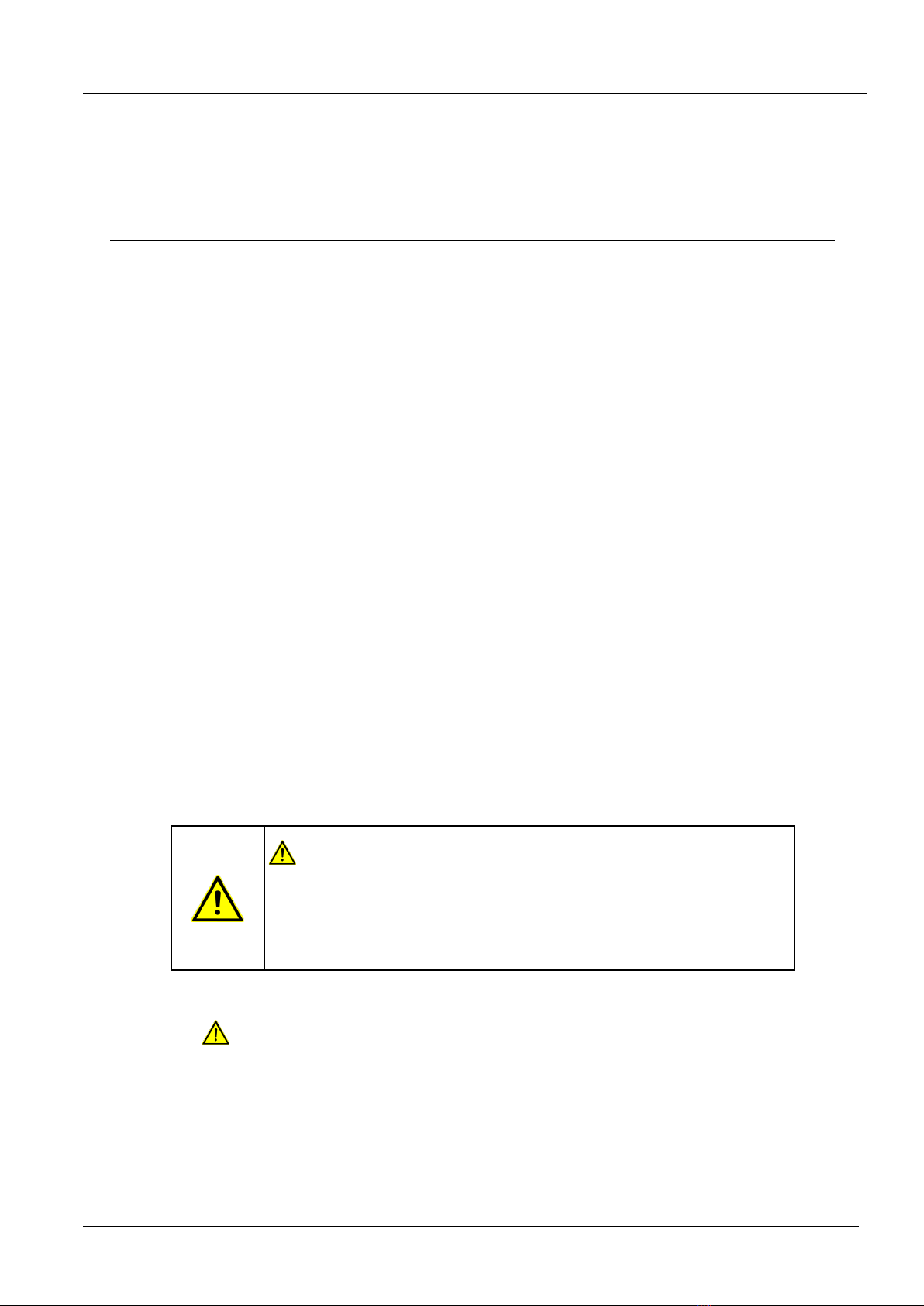
1.4 Structure of safety instructions
The safety instructions in this user manual are presented as follows:
Danger
symbol
SIGNAL WORD
Type of danger and its source
Possible consequences of violation.
Measure to prevent the danger.
If a dangerous situation could arise at a specific step, the safety instruction is displayed
immediately before this dangerous step and is shown as follows:
SIGNAL WORD
Type of danger and its source. Possible consequences of violation.
1. Measure to prevent the danger.
1 A
BOUT THIS MANUAL
About this manual Syscompact 2000 M pro
8
/ 98 822-175-2
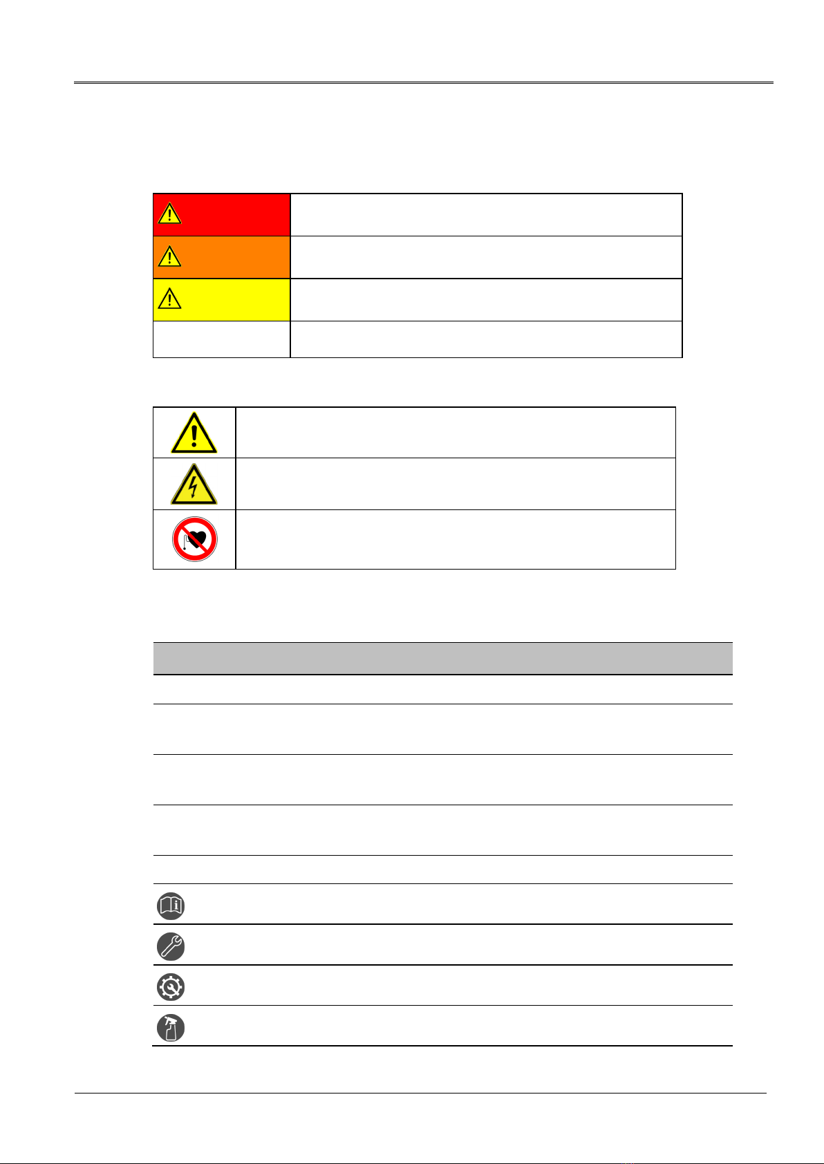
Danger levels
Signal words in the safety instructions specify the danger levels.
DANGER Will lead to severe injuries or death.
WARNING May lead to severe injuries or death.
CAUTION May lead to light to moderate injuries.
NOTICE May lead to material damage.
Danger symbols
General danger
Risk of electric shock
Dangerous for persons with pacemakers
1.5 View Settings
Symbol Meaning
You are requested to perform an action.
1.
2. ...
Perform the actions in this sequence.
a.
b. ...
If an operation consists of several operating steps, they are specified with "a, b, c".
Perform the operating steps in this sequence.
1
2 ...
Numbering in the legend
List
Indicates further information on the topic.
Indicates tools required for the subsequent tasks.
Indicates spare parts required for the subsequent tasks.
Indicates required cleaning agents.

Syscompact 2000 M pro About this manual
822-175-2 9 / 98
1.6 Note on the screenshots and graphics used
The screenshots and graphics used are intended to illustrate the procedure and may differ
slightly from the actual state.

For your safety Syscompact 2000 M pro
10
/ 98 822-175-2
All BAUR devices and systems are reliable and are manufactured as per state-of-the-art
technology. The individual parts and the finished devices are subject to continuous testing by
our qualified personnel as part of our quality assurance system. Each device is fully tested
before delivery.
However, the operational safety and reliability in practice can be achieved only when all
necessary measures have been taken. The responsible body1and operator2of the device or
system are responsible for planning these measures and monitoring their implementation.
Before operating the device or system you should read and understand this user manual and
the user manuals of all integrated devices.
2.1 Intended use
The portable Syscompact 2000 M pro cable fault location system is used for cable fault
location and cable testing in low- and medium-voltage cables up to 65 km length.
If the system is not used in accordance with this stipulation, safe operation cannot be
guaranteed. The user is liable for any damage to persons and property resulting from incorrect
operation!
Proper use also includes
compliance with all instructions in this user manual, and all other applicable documents,
compliance with the technical data and connection requirements given on the rating plate
and in the user manual and any other applicable documents,
compliance with the inspection and maintenance instructions for the system and its
components.
2.2 Instructions for the operator
The product may be operated only by authorised and trained electrical engineers. An electrical
engineer is a person who, owing to his professional education (electrical engineering),
knowledge, experience and familiarity with the applicable standards and regulations, can
assess the tasks assigned to him and detect possible dangers.
In addition, the operator must have:
Knowledge of the technical equipment and operation of the product
Knowledge of the testing and measurement procedures
Knowledge of plant engineering (cable types, switchgear, etc.).
1Responsible body is the person or group that is responsible for the safe operation of the device and its
maintenance (EN 61010-1, 3.5.12).
2Operator is the person who uses the device for its intended purpose (according to the definition of user in
compliance with EN 61010-1, 3.5.11).
2 F
OR YOUR SAFETY

Syscompact 2000 M pro For your safety
822-175-2 11 / 98
2.3 Avoiding dangers, taking safety measures
When installing the test system and operating Syscompact 2000 M pro observe the
following rules and guidelines:
Accident prevention and environment protection rules applicable for your country
Safety instructions and regulations of the country where Syscompact 2000 M pro is
being used (according to the latest version)
EU/EFTA countries: EN 50191 Installation and operation of electric testing systems
Other countries: The standard for installation and operation of electric testing systems
applicable for your country
EU/EFTA countries: EN 50110 Operation of electric systems
Other countries: The standard for operating electric systems applicable for your
country
If necessary, other national and international standards and guidelines in accordance
with the latest applicable version
Local safety and accident prevention regulations
Operational insurance association regulations (if any)
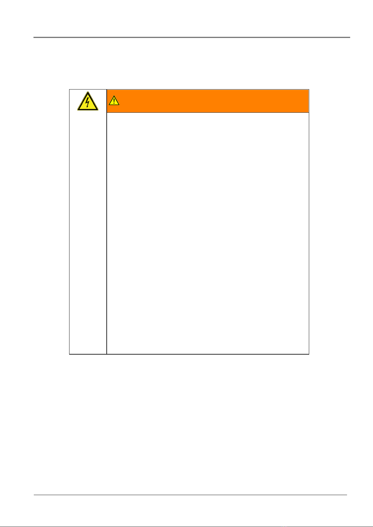
2.3.1 Forbidden for persons with pacemakers
DANGER
Magnetic and electromagnetic fields in the immediate
surroundings of electric equipment
It is dangerous for persons with pacemakers and metal implants to
stand in the immediate surroundings of electric equipment.
Magnetic and electromagnetic fields can damage and adversely affect
the function of pacemakers and metal implants. This can be dangerous
for the health of the concerned persons.
Persons with pacemakers and metal implants must not stand close
to high-voltage systems.
2.3.2 Operation only in a technical secure state
Safety, function and availability depend on the proper condition of the system.
Operate the system and the integrated devices only in a technical perfect condition.
In case of damage and malfunction, immediately stop the system, mark it accordingly and
have the faults rectified by appropriately qualified and authorised personnel.
Comply with the inspection and maintenance conditions.
Use only accessories and original spare parts recommended by BAUR. The use of spare
parts, accessories and special facilities that are not tested and approved by BAUR could
adversely affect the safety, function and characteristics of the product.

For your safety Syscompact 2000 M pro
12
/ 98 822-175-2
2.3.3 Checking and maintaining the safety devices
The safety devices must be inspected regularly for proper condition and function. The
Syscompact 2000 M pro must not be operated in the case of defects or non-functional safety
devices.
The safety devices must not be changed, bridged or switched off.
2.3.4 No operation during condensation
Condensation can form in devices and systems due to temperature fluctuations and high air
humidity, which in some components can result in leakage currents, flashovers and
short-circuits.
Maximum danger arises when relatively high air humidity and temperature fluctuations occur
in a device consecutively, which is the case when storing the system or device in an unheated
room or when placed outdoors, for example. When the system or device is then exposed to a
high ambient temperature, the cold device surfaces cool the air in the immediate vicinity, which
leads to formation of condensation even inside the device.
During this process, two factors are crucial:
The higher the relative air humidity, the faster the dew point is reached and water is
condensed.
The higher the temperature difference between the surfaces and the ambient air, the
stronger the tendency for condensation.
Always prevent condensation in devices. Temper the device and system before and during
the measurements so that no condensation occurs.
2.3.5 No operation in areas with risk of explosion and fire
Measurements in direct contact with water, in environments with explosive gases and in areas
with fire risks are not permitted. Possible danger areas include e.g. chemical factories,
refineries, paint factories, paint shops, cleaning plants, mills and stores of milled products,
tank and loading plants for combustible gases, liquids and solid matter.
2.3.6 Dangers when working with high voltage
When performing tests and measurements with the system, dangerous - at times a very high -
voltage is generated that is fed to the test object via an HV connection cable.
Personnel need to pay special attention and must be very careful while working with high
electric voltage.
Commissioning and operation of the system are permitted only in compliance with the
EN 50110 and EN 50191 (EU/EFTA countries) or with standards applicable in your country.
Observe 5 safety rules
Comply with the following safety rules before beginning tasks in and on the electrical plant:
1. Disconnect the test object.
2. Secure against re-connection.
3. Verify absence of operating voltage.
4. Earth and short all phases.
5. Provide protection against adjacent live parts.

Syscompact 2000 M pro For your safety
822-175-2 13 / 98
DANGER
High electric voltage
Danger to life or risk of injury due to electric shock.
Before commencing work, the operator must assess the risks for the
specific working conditions. Protective measures are based on the
risk assessment and must be followed within the workplace.
Connect the system as described in this user manual.
In particular earth the test object and system properly.
Observe the warning and safety signs on the system. Always check
whether the warning signs are available and are legible.
Never put the safety devices out of operation. It is forbidden to
bypass the safety devices.
Ensure that adjacent live parts are secured against accidental
contact and flashovers with suitable covers (insulation mats,
insulating safety plates).
Cordon off all metal parts in the area of the test object terminals
(connection point and far end). Insulate and earth the metal parts to
avoid dangerous charges.
After a measurement - after switching off the device or system - the test
object can still be live with dangerous voltage.
Before lifting the safety measures, all live parts must compulsorily be
discharged, earthed and short-circuited.
DANGER
Arcing fault when establishing a connection
Danger of burn injuries and electro-ophthalmia due to arcing fault.
Use suitable personal protective equipment to protect against arcing
faults.
Cover the adjacent live parts with an insulating material.
Use only undamaged connection cables.
Secure the connection points and far end of the test object.
Use special locking devices to lock connection points.
For your safety Syscompact 2000 M pro
14
/ 98 822-175-2
2.3.7 Danger during the system’s surge mode
WARNING
Potential differences between the system and the earth
Danger to life or risk of injury due to electric shock.
Potential differences between the system and the earth are possible
during surge mode when the system is positioned on the cable route.
The greatest potential difference and dangerous contact voltage will
occur in the case of a fault due to earth contact in a plastic-insulated low
voltage cable without shielding.
Fault is near the system:
Voltage drops at the fault location. There is risk of electric shock if a
person is standing over the fault location and touches the system
connected to the station earth.
Fault is far away from the system:
As the system is at the same potential as the station earth, there can be
a voltage difference between the system and the neutral earth in the
event of a cable fault, which can lead to rising potential of the station
earth. There is risk of electric shock if a person touches the system
connected to the station earth.
Place the system at a distance of several meters to the cable route
or cable fault location.
When positioning over the cable route, do not use measurement
methods that use a surge voltage and do not isolate the system.
If it is not possible to avoid the hazard by means of a potential increase,
take the following safety measures:
If operating in ‘surge mode’, cordon off the system at distance of at
least 1.5 m.
During surge mode, people may only stand outside the cordoned off
area.
Syscompact 2000 M pro For your safety
822-175-2 15 / 98
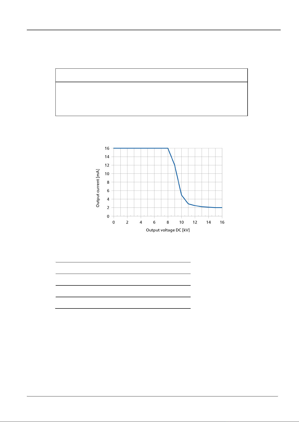
2.3.8 Maximum permissible output current in DC voltage mode
NOTICE
The device may be damaged by an excessive output current
An excessive output current during DC voltage mode can generate high thermal
loads. This will damage the transformer.
When using DC voltage mode, observe the maximum permissible output current.
The following illustrates the maximum permissible output current depending on the output
voltage (DC voltage).
Examples of max. permissible output currents:
Output voltage (DC) Maximum output current
Up to 8 kV 16 mA
10 kV 5 mA
12 kV 2.5 mA
16 kV 2 mA
2.3.9 TDR measurement on live cables
The IRG 2000 may only be used on live cables in the following scenarios:
For TDR measurements (methods: TDR, TDR Continuous and TDR Trigger)
If the voltage-proof input is enabled (parameter Voltage proof > On)
In electric circuits up to AC 400 V
Note that working on live parts and plants can be fundamentally dangerous.

For your safety Syscompact 2000 M pro
16
/ 98 822-175-2
When connecting the device to the test object, during the preparation and while performing the
measurement, the user can come close to live parts. In so doing, there is danger of touching
the active parts directly or indirectly.
DANGER
Working in the vicinity of adjacent live parts
Danger to life or risk of injury due to electric shock.
Only use the supplied TDR connection cable with fuses.
If the TDR connection cable is used without a fuse or with another
type of fuse, the IRG 2000 must not be connected to a live cable.
During connection, implementation and monitoring of the
measurement, protection must be guaranteed for all plant parts,
either
through safety devices, insulating cover material
or by adhering to the necessary safety distances. Safety
distances depend on the voltage level, plant model, personnel
qualification and available space.
In this regard, comply with EN 50110 or the applicable standards in
your country as well as the relevant national and local accident
prevention regulations.
Working in the vicinity of open cables or faulty systems is forbidden.
Notify the responsible authorities immediately.
Use suitable personal protective equipment to protect against arcing
faults.
To assess the local conditions adequately, provide sufficient lighting
at the work place.
2.3.10 Dangers from road traffic
As tasks with systems are often carried out in the road traffic area, when assessing the
danger also consider this danger area.
When setting up the system, secure the work place and during testing and measurement
tasks, observe the country-specific road traffic regulations, applicable national work safety
and accident prevention regulations and local conditions.
Moreover, dangers for the test personnel and road users must be ruled out. Test personnel
must wear high visibility clothing that can be identified clearly by road users.
2.3.11 Guaranteeing immediate measures in an emergency
The device may be operated only if a second person with visual and audio contact to the tester
is present and is in the position to detect possible dangers and to act immediately and
properly.
2.3.12 Safety locking feature against unauthorised operation
When leaving the device or the system, press the emergency off button and remove the
key.
Keep the key in a place that is inaccessible for unauthorised persons.

Syscompact 2000 M pro For your safety
822-175-2 17 / 98
2.4 Special personal protective equipment
Personal protective equipment based on the risk assessment for the relevant working
conditions is part of the safety concept of BAUR systems.
Observe the internal operating instructions and the safety instructions applicable in your
country.
The following safety equipment according to the state of the art can be necessary depending
on the specific conditions in the work place:
Protection against electrostatic charging,
crushing, slipping and other accidents:
Safety footwear
Protection against electric dangers (arcing fault): Tested safety clothing
Insulating helmet with visor
Insulating protective gloves
NH fuse puller with cuff
Protection against noise: Ear protection
Protection against dangers from road traffic: High-visibility vest according to EN 471
(Protection class 2) or according to the
applicable standards in your country for
high-visibility clothing for commercial use.
Important: No high-visibility vests while
working with electric arc hazard!
Hand protection: Safety gloves

Product information Syscompact 2000 M pro
18
/ 98 822-175-2
3.1 Overview of the available cable fault location methods
With Syscompact 2000 M pro, you can use any of the following fault location methods:
Cable testing with DC voltage
Time Domain Reflectometry (TDR)
Secondary-multiple impulse method (SIM/MIM)
Impulse current method (ICM)
Acoustic pin-pointing
3 P
RODUCT INFORMATION

Syscompact 2000 M pro Product information
822-175-2 19 / 98
3.2 Full illustration of Syscompact 2000 M pro
No. Element Function
1 Cable compartment Provides access to the ports of the IRG 2000 time domain reflectometer
2 IRG 2000 time
domain reflectometer
Is used to perform and evaluate the cable fault pre-location
Further information: Chapter IRG 2000 time domain reflectometer (on page 21)
3 System control panel Is used to switch the system on and off and control the surge voltage generator
Further information: Chapter System control panel (on page 20)
4 HV connection cable Is used to connect the Syscompact 2000 M pro to the test object
5 Discharge and earth
rod
Is used to discharge and earth the test object
6 Rating plate Contains the technical data and connection requirements for the system
Further information: Chapter Markings on the system (on page 27)
7 Protective earthing
connection
Is used to connect the protective earthing
8 Safety notice Warns against high touch current
Further information: Chapter Markings on the system (on page 27)
9 Mains connection Is used to connect the system to the mains voltage

Product information Syscompact 2000 M pro
20
/ 98 822-175-2
3.2.1 System control panel
No. Element Function
1 On/Off switch Is used to switch on and off the system’s power supply
2
Status LEDs
Displays the operational earth monitoring status:
Green: The operational earthing is connected correctly. The resistance
between operational and protective earthing is < 4 ohm.
Red: There is a problem with the operational earthing. The resistance
between operational and protective earthing is > 4 ohm.
When the LED is illuminated red, the system cannot be operated. Further
information: Chapter Fault indication with status LEDs (on page 87)
Displays the surge protective device status:
Green: The surge protective device is working and protecting the system
from overvoltage.
Red: The surge protective device is damaged.
When the LED is illuminated red, the system cannot be operated.
3 key
Moves the system to the Ready to switch on operating state.
4 key Moves the system to the In operation operating state.
5 key Switches off the high voltage and moves the system to the Ready for operation
operating state:
All test voltage supplies are switched off.
The internal capacitor and the test object are discharged.
6 Display with keys Is used to select the methods and set the various parameters
The lowest line of the display shows the function of the associated key.
7 HV adjustment keys
( / )
Are used to increase or decrease the output voltage
8 Indicator lights Indicate the system operating state:
Green: Ready for operation
Red (flashing): Ready to switch on
Red: In operation
Table of contents
Popular Cable Tester manuals by other brands

Radiodetection
Radiodetection RD8100 Operation manual

Kurth Electronic
Kurth Electronic KE6000 quick start guide

Klein Tools
Klein Tools VDV Commander VDV501-097 instruction manual

Triplett
Triplett WireMaster HDMI2 instruction manual

Softing
Softing WireXpert 4500 user manual

WJG
WJG ST-50 USB Reference manual

Greenlee
Greenlee PA1594 instruction manual

Prokit's Industries
Prokit's Industries HT-7059 user manual

Velleman
Velleman VTTEST15 user manual

Greenlee
Greenlee NETcat NC-100 instruction manual

Steren
Steren HER-605 instruction manual

Sperry instruments
Sperry instruments Cable-Test TT64200 operating instructions


