Baur DTA 100 C User manual
B A U R G m b H ▪R a i f f e i s e n s t r . 8 ▪6 8 3 2 S u l z , A u s t r i a
T + 4 3 5 5 2 2 4 9 4 1 - 0 ▪F + 4 3 5 5 2 2 4 9 4 1 - 3 ▪w w w . b a u r . e u ▪h e a d o f f i c e @ b a u r . a t
User manual
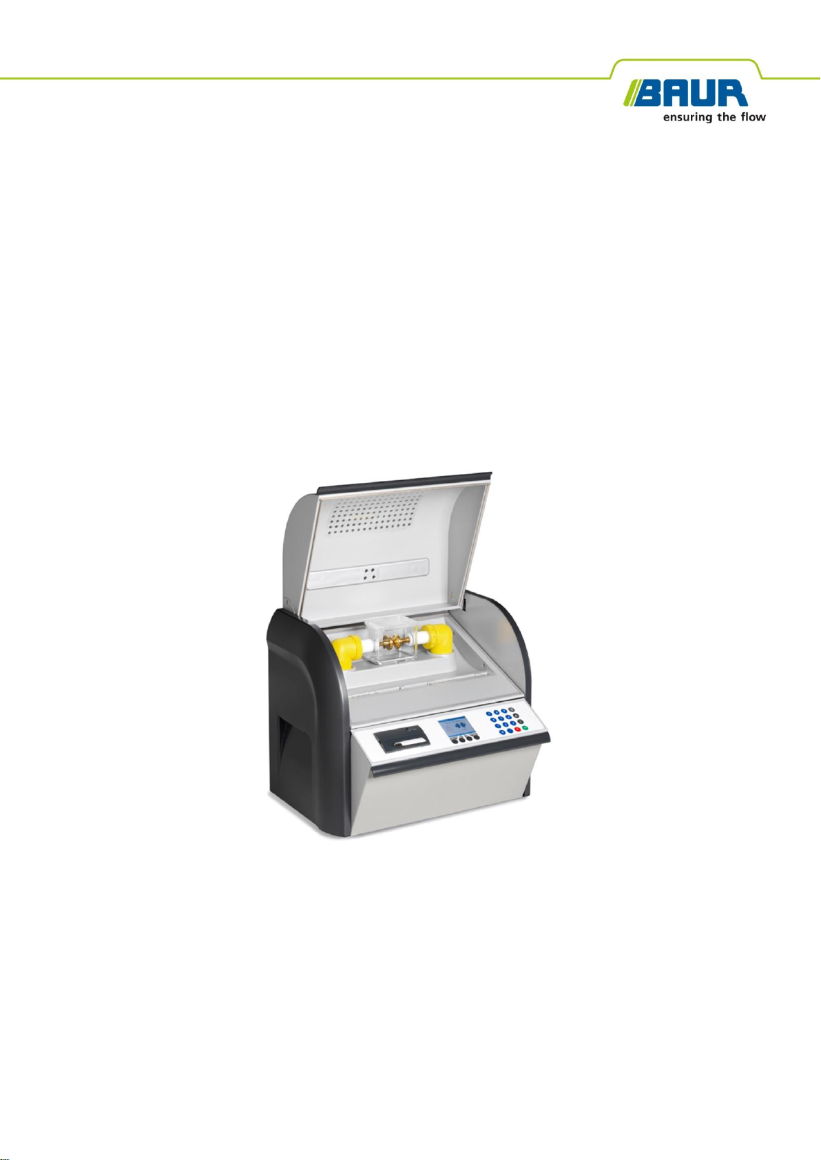
Oil breakdown voltage tester
DTA 100 C
phd

Copyright © 2019
All rights reserved.
Reproduction, circulation in any form whatsoever, publishing on online services or the Internet, as well
as duplication on data carriers, even in part or in an amended format, is allowed only with prior written
permission of BAUR GmbH, 6832 Sulz, Austria.
We reserve the right in the interests of our customers to make amendments as a result of further
technical development. Illustrations, descriptions and scope of supply are therefore not binding.
The names of products and companies are the trademarks or brand names of the relevant companies.

DTA 100 C Table of contents
822-129-8 iii / 90
Table of contents
1About this manual ....................................................................................... 6
1.1 Using this manual ................................................................................ 6
1.2 Applicability of the instructions............................................................. 6
1.3Structure of safety instructions ............................................................ 6
1.4 View Settings ....................................................................................... 7
1.5 Note on the screenshots and graphics used ....................................... 8
2For your safety............................................................................................. 9
2.1 Instructions to the user......................................................................... 9
2.2 Intended use ......................................................................................10
2.3 Avoid dangers, take safety measures................................................ 10
2.3.1 Dangers when working with electric voltage........................11
2.4 Special personal protective equipment.............................................. 12
3Product information .................................................................................. 13
3.1 Full illustration....................................................................................13
3.2 Operating and display elements ........................................................ 16
3.3 USB interface.....................................................................................17
3.4 Power supply ..................................................................................... 17
3.5 Rating plate........................................................................................ 18
4Technical data............................................................................................ 19
5Basic insulating oil test procedure.......................................................... 20
6Operating the oil breakdown voltage tester............................................ 21
6.1 Menu navigation................................................................................. 21
6.2 Entering numbers............................................................................... 21
6.3 Symbols and abbreviations on the display ........................................ 22
6.4 Main menu .........................................................................................23
6.5 Information on the oil breakdown voltage tester................................24
6.5.1 Information on the USB interface......................................... 24
7Commissioning.......................................................................................... 25
7.1 Checks to perform before commissioning .........................................25
7.2 Installing the oil breakdown voltage tester.........................................26
7.3 Earthing the oil breakdown voltage tester.......................................... 26
7.4 Replacing the electrodes ................................................................... 27
7.5 Clean the electrodes.......................................................................... 28
7.6 Setting an electrode gap....................................................................28

Table of contents DTA 100 C
iv / 90 822-129-8
7.7 Fill and use the test vessel ................................................................ 29
7.7.1 Instructions for sampling......................................................30
7.7.2 Insert the test vessel............................................................ 31
7.8 Turning on the oil breakdown voltage tester...................................... 32
8Device settings .......................................................................................... 33
8.1 Set display brightness........................................................................33
8.2 Select language ................................................................................. 34
8.3 Switch printer on/off........................................................................... 34
8.4 Overwrite measurement logs............................................................. 35
8.5 Configure the IEC 60156:2018 settings.............................................35
8.5.1 Setting the hold time before the first measurement............. 36
8.5.2 Adjusting the stirrer.............................................................. 37
8.5.3 Setting the electrode shape .................................................38
8.6 Configure the ASTM settings............................................................. 39
8.6.1 Display individual breakdown values ................................... 39
8.6.2 Set the hold time before the first measurement...................40
8.7 Configure settings for user-defined measurements........................... 41
8.8 Set date..............................................................................................42
8.9 Set time.............................................................................................. 43
8.10 Reset settings ....................................................................................43
9Standardised measurement ..................................................................... 44
9.1 Overview of standards ....................................................................... 44
9.2 Carry out a standardised measurement ............................................45
10 Quick test ................................................................................................... 48
11 User-defined measurement ...................................................................... 51
11.1 Creating a user-defined measurement.............................................. 52
11.1.1 Overview of templates.......................................................... 53
11.1.2 Selecting a template............................................................. 54
11.1.3 Setting the hold time before the first measurement............. 54
11.1.4 Setting the stirring time during the hold time ....................... 55
11.1.5 Setting the slew rate for the test voltage.............................. 55
11.1.6 Setting the duration of the pauses between
measurements ..................................................................... 56
11.1.7 Setting the stirring time in the pauses..................................56
11.1.8 Setting the number of measurements.................................. 57
11.1.9 Setting the maximum output voltage....................................57
11.1.10 Setting the withstand voltage............................................... 58
11.1.11 Selecting which measured values are not to be
evaluated..............................................................................59

DTA 100 C Table of contents
822-129-8 v / 90
11.1.12 Saving user-defined measurements....................................60
11.2 Running a user-defined measurement .............................................. 61
11.3 Editing or deleting a user-defined measurement...............................63
12 Display of measurement results .............................................................. 64
12.1 Measurement log as printout ............................................................. 65
12.2 Measurement log on the display........................................................66
13 Putting the device out of operation ......................................................... 67
14 BAUR ITS Lite software for measurement data management .............. 68
14.1 Description of function ....................................................................... 68
14.2 Installing ITS Lite ...............................................................................69
14.3 Starting ITS Lite................................................................................. 69
15 Checking the measurement accuracy of the oil breakdown voltage
tester (optional).......................................................................................... 70
16 Maintenance............................................................................................... 71
16.1 Cleaning the oil breakdown voltage tester.........................................72
16.2 Replacing the printer paper roll.......................................................... 74
16.3 Replacing the printer ink ribbon......................................................... 76
16.4 Replacing the fuse ............................................................................. 77
16.5 Calibration.......................................................................................... 77
16.6 Ordering accessories and spare parts............................................... 78
17 Faults .......................................................................................................... 79
17.1 Troubleshooting ................................................................................. 79
17.2 Error messages and corrective measures......................................... 80
18 Transportation and storage...................................................................... 81
18.1 Packaging .......................................................................................... 81
18.2 Transportation.................................................................................... 81
18.3 Storage .............................................................................................. 82
19 Warranty and After Sales.......................................................................... 82
20 Disposal...................................................................................................... 83
20.1 Disposing of the device......................................................................83
20.2 Disposing of the insulating oil ............................................................83
21 Delivery includes and Options................................................................. 84
22 Declaration of conformity......................................................................... 85
23 Index............................................................................................................ 86

About this manual DTA 100 C
6 / 90 822-129-8
1.1 Using this manual
This user manual contains all necessary information that is needed for the commissioning
and operation of the described product.
Read this user manual completely before operating the product for the first time.
Consider this user manual to be a part of the product and store it in an easily accessible
location.
If this user manual is lost, please contact BAUR GmbH or your nearest BAUR
representative (http://www.baur.eu/baur-worldwide).
1.2 Applicability of the instructions
These operating instructions apply to the DTA 100 C with the firmware version from 1.16.
The details of the firmware version currently installed can be found under:
Main menu > Tools > Info
1.3 Structure of safety instructions
The safety instructions in this user manual are presented as follows:
Danger
symbol
SIGNAL WORD
Type of danger and its source
Possible consequences of violation.
Measure to prevent the danger.
If a dangerous situation could arise at a specific step, the safety instruction is displayed
immediately before this dangerous step and is shown as follows:
SIGNAL WORD
Type of danger and its source. Possible consequences of violation.
1. Measure to prevent the danger.
1 ABOUT THIS MANUAL

DTA 100 C About this manual
822-129-8 7 / 90
Danger levels
Signal words in the safety instructions specify the danger levels.
DANGER
Will lead to severe injuries or death.
WARNING
May lead to severe injuries or death.
CAUTION
May lead to light to moderate injuries.
NOTICE
May lead to material damage.
Danger symbols
General danger
Risk of electric shock
Warning about combustible materials
1.4 View Settings
Symbol
Meaning
You are requested to perform an action.
1.
2. ...
Perform the actions in this sequence.
a.
b. ...
If an operation consists of several operating steps, they are specified
with "a, b, c". Perform the operating steps in this sequence.
1
2 ...
Numbering in the legend
List
Indicates further information on the topic.
Indicates tools required for the subsequent tasks.
Indicates spare parts required for the subsequent tasks.
Indicates required cleaning agents.

About this manual DTA 100 C
8 / 90 822-129-8
1.5 Note on the screenshots and graphics used
The screenshots and graphics used are intended to illustrate the procedure and may differ
slightly from the actual state.

DTA 100 C For your safety
822-129-8 9 / 90
All BAUR devices and systems are manufactured according to the state of the art and are
safe to operate. The individual parts and the finished devices are subject to continuous
testing by our qualified personnel as part of our quality assurance system. Each device and
system is tested before delivery.
However, the operational safety and reliability in practice can be achieved only when all
necessary measures have been taken. The responsible body
1
and operator
2
of the device or
system are responsible for planning these measures and monitoring their implementation.
Make sure that the responsible body and persons working with the device or system have
carefully read through and understood the user manual for the DTA 100 C, as well as the
user manuals for all associated devices, before starting work.
The responsible body and operator of the device or system are responsible for any injuries
or damage resulting from non-compliance with this user manual.
2.1 Instructions to the user
The product may only be operated by authorised and trained electrical engineers. An
electrical engineer is a person who, owing to his professional education (electrical
engineering), knowledge, experience and familiarity with the applicable standards and
regulations, can assess the tasks assigned to him and detect possible dangers.
In addition, the user must have:
Knowledge of the technical equipment and operation of the DTA 100 C
Knowledge of the testing and measurement procedures
Knowledge of the electrical insulating materials, in particular the insulating oil, and how
to handle them.
1
Responsible body is the person or group that is responsible for the safe operation of the device and its
maintenance (EN 61010-1, 3.5.12).
2
Operator is the person who uses the device for its intended purpose (according to the definition of user in
compliance with EN 61010-1, 3.5.11).
2 FOR YOUR SAFETY

For your safety DTA 100 C
10 / 90 822-129-8
2.2 Intended use
The powerful BAUR DTA 100 C oil breakdown voltage tester automatically measures the
electrical breakdown strength of insulating liquids fully.
Note: With the DTA 100 C you can test insulating liquids with tan δ values < 4.5 and specific
resistance ρ > 30 MΩm.
If the device is used without observing this condition, safe operation cannot be guaranteed.
The operator or user is liable for any damage to persons and property resulting from
incorrect operation.
Proper use also includes
Compliance with all instructions in this user manual,
Compliance with the technical data and connection requirements given on the rating
plate and in the user manual,
Compliance with the inspection and maintenance tasks.
2.3 Avoid dangers, take safety measures
When operating the DTA 100 C, observe the following rules and guidelines:
Accident prevention and environment protection rules applicable for your country
Safety instructions and regulations of the country where the DTA 100 C is being
used (according to the latest version)
Any relevant national and international standards and guidelines in the latest
applicable version:
Local safety and accident prevention regulations
Employers’ liability insurance association regulations (if any)
Technically secure state of the product
Safety, function and availability depend on the proper condition of the product. Upgrades,
modifications or alterations to the product are essentially prohibited.
Operate the product only in a technically perfect condition.
In the event of damage or malfunctions, take the product out of operation immediately,
mark it accordingly and have the faults rectified by appropriately qualified and authorised
personnel.
Comply with the inspection and maintenance conditions.
Use only accessories and original spare parts recommended by BAUR. The use of spare
parts, accessories and special fittings that are not tested and approved by BAUR could
adversely affect the safety, function and characteristics of the product.
Never take apart the product. Inside the product there are no components that could be
serviced or repaired by the user.
No operation with condensation
Condensation can form in devices and systems due to temperature fluctuations and high air
humidity, which in some components can lead from leakage currents and flashovers up to
short-circuit.
Maximum danger arises when relatively high air humidity and temperature fluctuations occur
in a device consecutively, e.g. which is the case when storing the device in an unheated
room or when placed outdoors. When the device is then exposed to a high ambient

DTA 100 C For your safety
822-129-8 11 / 90
temperature, the cold device surfaces cool the air in the immediate vicinity, which leads to
formation of condensation even inside the device.
In this process, two factors are crucial:
The higher the relative air humidity, the faster the dew point is reached and water is
condensed.
The higher the temperature difference between the surfaces and the ambient air, the
stronger the tendency for condensation.
Always prevent condensation in devices. Temper the device and system before and
during the measurements so that no condensation occurs.
No operation in areas with risk of explosion and fire
Measurements in direct contact with water, in environments with explosive gases and in
areas with fire risks are not permitted.
Cleanliness of oil breakdown voltage tester
To achieve reliable measurement results, the oil breakdown voltage tester, the test chamber,
the HV isolators, the test containers and all tools that come into contact with the oil must be
clean.
BAUR GmbH recommends cleaning the HV isolators at least once a year to guarantee
maximum accuracy.
HV isolators may be cleaned only by qualified technical staff authorised by BAUR.
In case of questions, please contact BAUR GmbH or your local BAUR representative
(http://www.baur.eu/baur-worldwide).
Lifting and carrying the oil breakdown voltage tester
The DTA 100 C oil breakdown voltage tester weighs up to 39 kg. It is recommended to
seek the help of another person to lift or carry the device.
2.3.1 Dangers when working with electric voltage
A dangerous voltage of up to 100 kV is generated during measurements with the
DTA 100 C. Operating personnel need to pay special attention and must be very careful
while working with electric voltage.
DANGER
Dangerous electric voltage
Danger to life or risk of injury due to electric shock
Connect the oil breakdown voltage tester as described in this user
manual.
Take particular care to ensure the oil breakdown voltage tester is
earthed properly.
Before carrying out any cleaning or maintenance, switch off the
device and remove the mains plug to ensure the oil tester is
completely disconnected from the mains voltage.

For your safety DTA 100 C
12 / 90 822-129-8
2.4 Special personal protective equipment
Personal protective equipment based on the risk assessment for the relevant working
conditions is part of the DTA 100 C safety concept.
Observe the national safety regulations and your company's working and operating
instructions.
Dependent on the conditions of the work place, use the following protective equipment:
Protection against electrostatic charging,
crushing, slipping and other accidents:
Safety footwear
Protection against electrical hazards (arcing
fault):
Certified safety clothing
Hard hat with visor
Insulating protective gloves
LV HRC fuse handle with sleeve
Protection against noise:
Ear protection
Protection against dangers from road traffic:
High visibility vest according to EN 471
(Protection class 2) or according to the
applicable standards in your country for high
visibility clothing for commercial use.
Important: No high visibility vest during tasks
with risk of arcs!
Hand protection:
Safety gloves

DTA 100 C Product information
822-129-8 13 / 90
3.1 Full illustration
Front view
No.
Element
Function
1
Handle
Used to open and close the protective cover
2
Protective cover
Used to protect against dust and oil
3
Safety switch
Used as a protective device
The protective cover must be closed in order to perform a
measurement.
3 PRODUCT INFORMATION

Product information DTA 100 C
14 / 90 822-129-8
No.
Element
Function
4
Test vessel with electrodes
Filled with insulating oil
The test vessels have a standard holding capacity of 0.4 litres and are
made of glass. They comply with the following standards:
IEC 60156 Fig. I or Fig. II
ASTM D877
ASTM D1816
The electrode shape is specified in the standards and is indicated on
the display before a measurement begins.
The figure illustrates the 0.4 litre test vessel in accordance with
IEC 60156 Fig. II with cover.
Further information:
Test vessel shapes –Chapter Delivery includes and Options (on
page 84)
Replacing the electrodes –Chapter Replacing the electrodes (on
page 27)
5
Oil collecting tray
Used to collect insulating oil
6
Integrated plain paper printer
Used to print the measurement logs
7
Fold-out operating unit
Used to operate the oil breakdown voltage tester
The operating unit contains the operator control panel and the
membrane keyboard.
Further information: Chapter Operating and display elements (on page
16)
Standard accessories
No.
Element
Function
1
Setting gauge
Used to set the electrode gap
2
Magnetic stirrer
Used to stir the oil sample
DTA 100 C Product information
822-129-8 15 / 90
No.
Element
Function
3
Lifting stick for magnetic
stirrer
Used to remove the magnetic stirrer from the oil sample
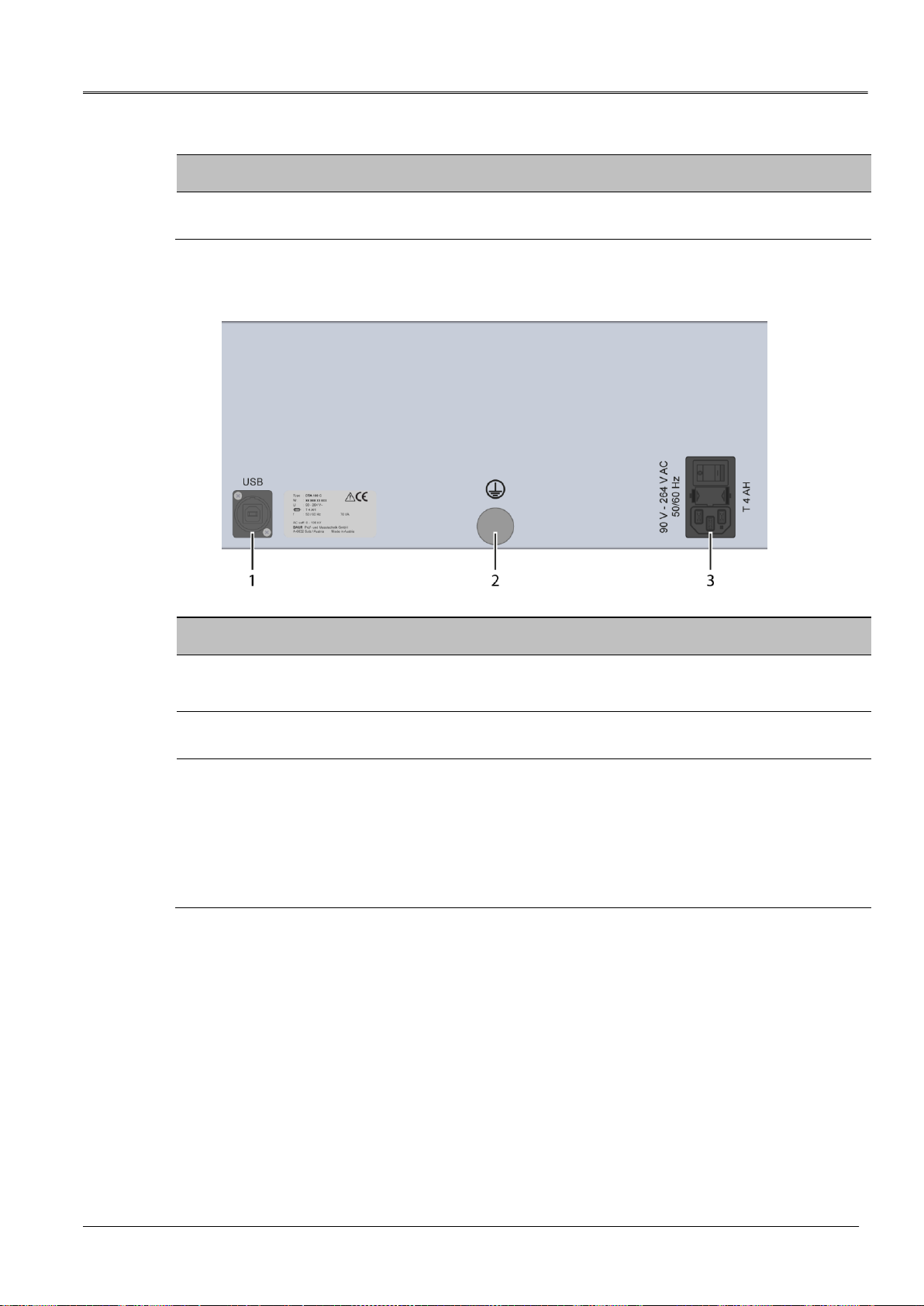
Rear view
No.
Element
Function
1
USB connection
Used to connect to a PC
Type of interface:USB Type B
2
Protective earthing
connection
Is used to connect the protective earthing
3
Mains connection
Is used to connect the device to the mains voltage (90 –264 V,
50/60 Hz)
The power supply connection comprises:
Power supply socket
Mains fuse, Type: T 4 AH
Mains switch
Product information DTA 100 C
16 / 90 822-129-8
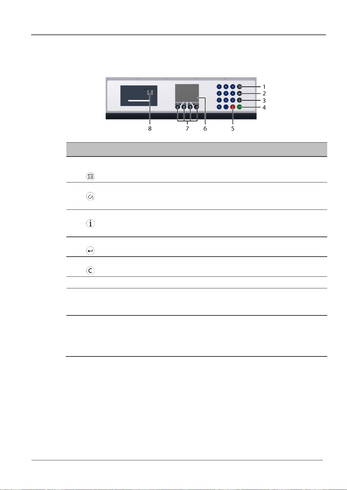
3.2 Operating and display elements
No.
Element
Function
1
Standardised measurement
button
Opens the Standardised measurement menu
Further information: Chapter Standardised measurement (on page 44)
2
Measurement logs button
Opens the Measurement logs menu
Further information: Chapter Display of measurement results (on page
64)
3
Info button
Displays the device information.
Further information: Chapter Information on the oil breakdown voltage
tester (on page 24)
4
Input button
Used to confirm the input
5
Delete button
Used to delete a character at the cursor position
6
Display
Show the menu of the device
7
Control keys
Used to navigate through the menu
Further information: Chapter Operating the oil breakdown voltage tester
(on page 21)
8
Printer operating keys
The paper feed button LF/SEL is used to feed in the printer paper
when the paper roll is replaced.
Further information: Chapter Replacing the printer paper roll (on
page 74)
The SET button is not assigned.
DTA 100 C Product information
822-129-8 17 / 90
3.3 USB interface
The USB interface is used:
to connect to a PC for communicating with the BAUR ITS Lite software for managing
measurement data (free download: http://www.baur.eu),
for firmware updates performed by a BAUR representative.
Type of interface:: USB Type B
3.4 Power supply
The voltage supply for DTA 100 C can be provided via an existing mains supply on site.
Permissible mains voltage: 90 –264 V
Permissible mains frequency: 50/60 Hz
NOTICE
Too high or too low mains voltage
A low mains voltage adversely affects the function of the system, a high mains
voltage can cause damage.
Ensure that the supply voltage matches the specifications on the rating plate.
Product information DTA 100 C
18 / 90 822-129-8
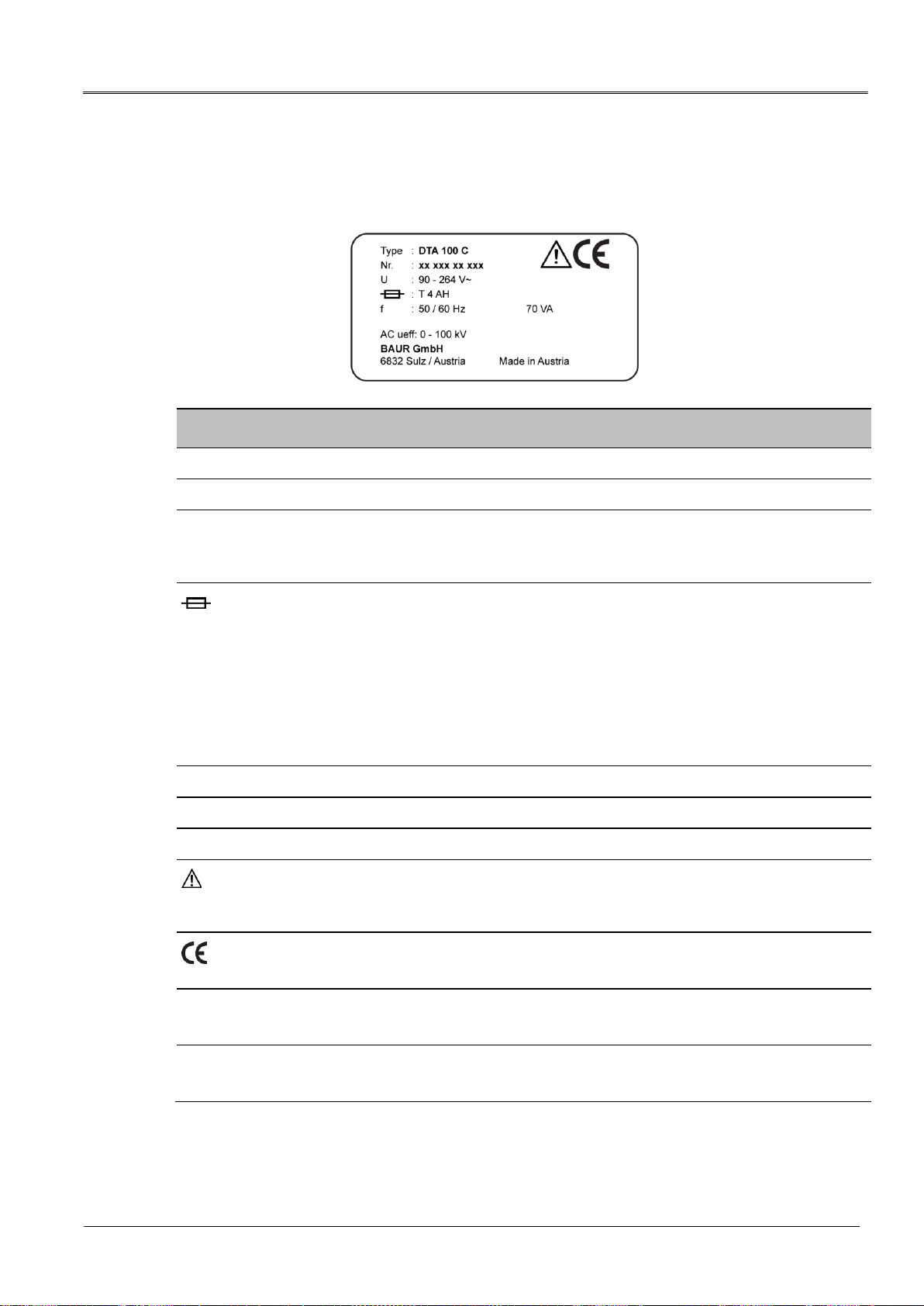
3.5 Rating plate
The rating plate is located on the back of the oil breakdown voltage tester.
Element
Description
Type
Device type
Nr.
Serial number
U
Supply voltage
If several supply voltages are possible, these are given consecutively one after
another.
Time characteristics and nominal current of the device fuse
Time characteristics:
Very Quick Acting (FF)
Quick Acting (F)
Medium (M)
Slow Blow (T)
Very Slow Blow (TT)
f
Mains frequency
VA
Max. recorded apparent output
AC ueff: 0 - 100 kV
Effective output AC voltage
General warning sign
Indicates that there is a potential risk of danger when using the product and hence
the user manual must be observed
CE mark
Indicates that the device or system conforms to CE.
BAUR GmbH
6832 Sulz / Austria
Name and address of the manufacturer
Made in Austria
Indicates the country in which the device was manufactured.
Austria: Austria


Basic insulating oil test procedure DTA 100 C
20 / 90 822-129-8
1. Installing the oil breakdown voltage tester
2. Connecting the oil breakdown voltage tester to the
power supply
3. Earthing the oil breakdown voltage tester (if
operated in a laboratory)
4. Turning on the oil breakdown voltage tester
5. Select the electrodes specified in the standard
6. Insert the electrodes in the test vessel
7. Set the electrode distance
8. Fill the test vessel with the oil sample
9. Insert the test vessel into the oil breakdown voltage
tester
10. Performing the measurement
11. Print and/or save the measurement log
12. Remove the test vessel from the oil breakdown
voltage tester
13. Dispose of the oil sample
14. Switch off the oil breakdown voltage tester
5 BASIC INSULATING OIL TEST PROCEDURE
Table of contents
Other Baur Test Equipment manuals


