Baur DPA 75 User manual

0-1
Fully Automatic
Insulating Oil Tester DPA 75
Designed for the fully automatic measuring of the
electric breakdown strength of insulants
Operating Instruction
12/98
Ident no. 822-073
BAUR Prüf- und Messtechnik GmbH
Raiffeisenstrasse 8, A-6832 Sulz / Austria Tel +43 / 55 22 / 49 41-0
Fax +43 / 55 22 / 49 4 13
e-mail: headoffice@baur.at
internet: http://www.baur.at

0-2
0-3
© BAUR Prüf- und Messtechnik GmbH,
A-6832 Sulz / Austria
All rights reserved.
No part of this publication may be produced,
transmitted, stored in a data processing system or
translated into another language without the written
permission of Baur/Sulz, Austria.
In the interest of our customers we reserve the rights
for modifications due to technical progress.
Illustrations, descriptions and delivery content are
therefore not binding.
Copyright
© Copyright by BAUR
Guide to this Operating Instruction
For fast finding of important information the
corresponding text passages are marked with symbols
(symbols not stated here are self-explaining):
More and special information concerning the respective
subject are available from BAUR.
Important unit information!
In any case, read carefully!
Important information text.
Subject to modification!
Observe
info signs!
☞
Copyright

0-4
BAUR Prüf- und Messtechnik GmbH,
Raiffeisenstrasse 8
A-6832-Sulz / Austria
or refer to your nearest BAUR representative.
Preface
Tel +43 / 55 22 / 49 41-0
Fax +43 / 55 22 / 49 41 3
This manual contains all information necessary for the
correct handling and use of the Fully Automatic
Insulating Oil Tester DPA 75.
Before using the DPA 75 unit please read carefully this
Operating Instruction.
If you have any question please contact directly:
Preface

0-5
- The Insulating Oil Tester DPA 75 is built in
accordance with today’s state of engineering and is
safe to operate.
Individual components and the finished unit are
inspected continually by our qualified staff within the
framework of our Quality Assurance Provisions.
Each unit is subjected to thorough testing prior to
shipment.
- It is imperative to every person who is involved with
the installation, start-up, operation and maintenance
to have read and understood the complete Operating
Instruction.
- The user is responsible for ensuring that no
unauthorized personnel works with the unit. He has
an obligation to report immediately any changes to
the unit which affect its safety.
- Use as directed:
The DPA 75 unit may be used exclusively for
insulating liquids with a flash point of ³110C (230F).
The local safety and accident prevention
regulations are always applicable to the operation
of the DPA 75 unit.
Safety Precautions
In any case read Operating
Instruction before using the
unit!
Only authorized personnel!
Use the DPA 75 unit as
directed!
Please read now and
avoid damage and
injury later!
Safety Precautions

0-6
At the customer’s written request we undertake to
repair or replace at our discretion and as quickly as
possible all parts that become faulty or useless as the
demonstrable result of poor material, faulty design or
defective execution.
We shall bear the costs of any faulty parts requiring
replacement, but not the costs of transport to us and
back to the customer, nor the costs of packing and
insurance!
The 12 month warranty time starts with delivery.
We shall not be liable for any damage resulting from
normal wear and tear, improper handling, non-
observance of Operating Instruction and safety
regulations.
We shall also refuse to accept any liability if the
customer carries out repairs or changes to the unit
himself or has others carry out them!
The warranty does not cover damage in transit,
batteries, fuses and any readjustments in accordance
with the Operating Instruction!
We draw attention in addition to the ‘General Terms of
Sales and Delivery’ of:
BAUR Prüf-und Messtechnik GmbH,
A-6832 Sulz / Austria
Warranty Terms
12 month warranty time
Warranty Terms

0-7
Contents
1. Product Information ....................................................................... 1-1
1.1 Test cycle .............................................................................. 1-2
1.2 Construction / Principle ......................................................... 1-3
1.3 Function and control elements .............................................. 1-5
1.4 Control panel......................................................................... 1-7
1.5 Menu overview...................................................................... 1-7
1.6 Technical data ....................................................................... 1-9
1.7 RBM switching off ............................................................... 1-11
2. Packing and Delivery ..................................................................... 2-1
2.1 Unpacking............................................................................. 2-1
2.2 Damage during transport ...................................................... 2-1
2.3 Check extent of delivery........................................................ 2-2
2.4Installation............................................................................. 2-4
3. Putting into Operation ................................................................... 3-1
3.1 Selecting language ............................................................... 3-2
3.2Adjust contrast of display ...................................................... 3-3
3.3 Set actual date ...................................................................... 3-4
3.4 Set actual time ...................................................................... 3-5
3.5 Cleaning of electrodes .......................................................... 3-6
4. Testing Preparations ..................................................................... 4-1
4.1 Checking battery state of charge .......................................... 4-1
4.2 Switching printer on/off.......................................................... 4-2
4.3 Enter report no. ..................................................................... 4-3
4.4Adjust electrode spacing ....................................................... 4-4
4.5 Sampling of insulating liquids ................................................ 4-5
4.6 Filling test vessel................................................................... 4-7
4.7 Carry out DPAtest ................................................................ 4-9
Contents

0-8
5. Standard Test.................................................................................. 5-1
5.1 Start standard test................................................................. 5-1
5.2 Indication of test results - standard test................................. 5-3
5.3 Printer report (option) - standard test .................................... 5-4
6. Customer-specific Test Cycle ...................................................... 6-1
6.1 Define and store customer-specific test cycle ....................... 6-1
6.2 Start customer-specific test cycle.......................................... 6-9
6.3 Indication of test results - customer-specific test cycle........ 6-10
6.4 Printer report (option) - customer-specific test cycle ........... 6-11
7. Single Test ..................................................................................... 7-1
7.1 Start single test ..................................................................... 7-1
7.2 Indication of test results - single test ..................................... 7-2
7.3 Printer report (option) - single test......................................... 7-2
8. Maintenance and Care ................................................................... 8-1
8.1 Replacing mains fuse............................................................ 8-1
8.2 Replacing printer ribbon (option) ........................................... 8-3
8.3 Replacing printer paper roll (option) ...................................... 8-4
9. Spare and Wearing Parts............................................................... 9-1
10. Test Standards............................................................................ 10-1
11. Index .............................................................................................11-1
1-1
Product Information
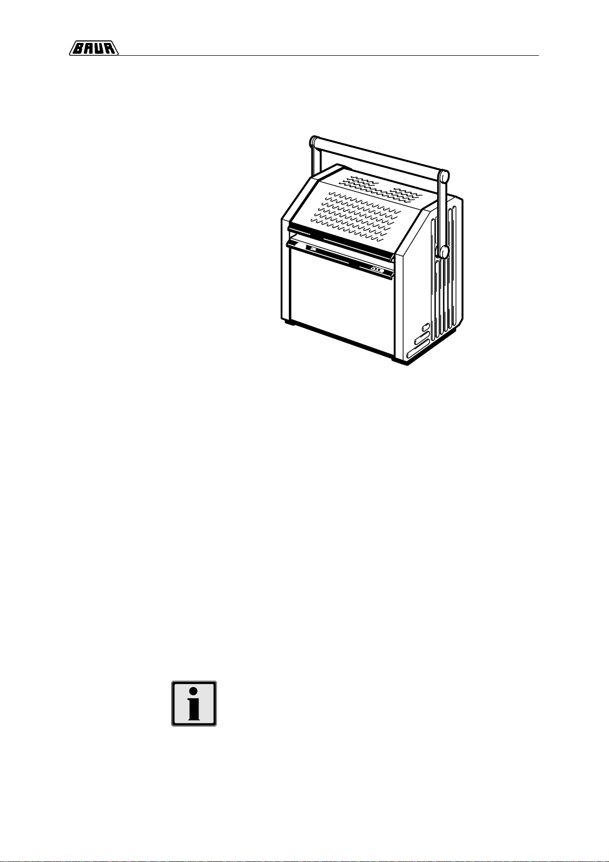
1. Product Information
The Insulating Oil Tester DPA 75 is used to measure
the electric breakdown strength of insulating
liquids (eg insulating oil of transformers etc).
The dissipation factor tan dand the relative
permittivity er, together with the breakdown voltage, are
the most important parameter for which insulating
liquids are tested.
The breakdown voltage shows the degree of
contamination by cellulose fibres and water.
For the operating safety of oil insulated high voltage
units the electrical breakdown strength of insulants is
the deciding factor.
For further information also see the technical report ‘Testing of
dielectric properties of insulating liquids’ by M. Krüger.
Obtainable from BAUR under no. 8602e.
The Insulating Oil Tester
DPA 75
Measuring the electric breakdown
strenght of insulating liquids
In all fig. units are shown with options
A judgement criterion for the quality of
insulating liquids

1-2
Product Information
1Open protective hood and remove test vessel.
Test vessel must comply with selected test standard.
2Insert electrodes corresponding to selected test
standard into the test vessel and adjust electrode
spacing.
3Fill insulating liquid into test vessel considering
standards
IEC 475 / VDE0370 part 3/2.80 and
IEC 156 / VDE0370 part 5
and insert test vessel into DPA unit again.
4Close protective hood.
5Fold out front panel.
The DPA unit is switched on automatically.
6Select desired test standard via function keys.
Before starting test pay attention to indicated and
actual electrode form and spacing:
13 pre-programmed test standard cycles are
available with the DPA 75 unit. Additionally, all
parameters can be freely programmed acc. to a
customer-specific test cycle.
7After starting the test cycle the measured data are
automatically reported via integrated printer (option).
8After conclusion of the test cycle close front panel.
The DPA unit is switched off automatically.
1.1 Test cycle
For more and detailled information in operating the
DPA 75 unit refer to section 4. Testing Preparations.
1
23
4
5
6
7
8
selected standard
electrode form
electrode spacing
warning sign
(flashing)
MENU START
IEC 156/63
2.5 mm
☞
1-3
Product Information
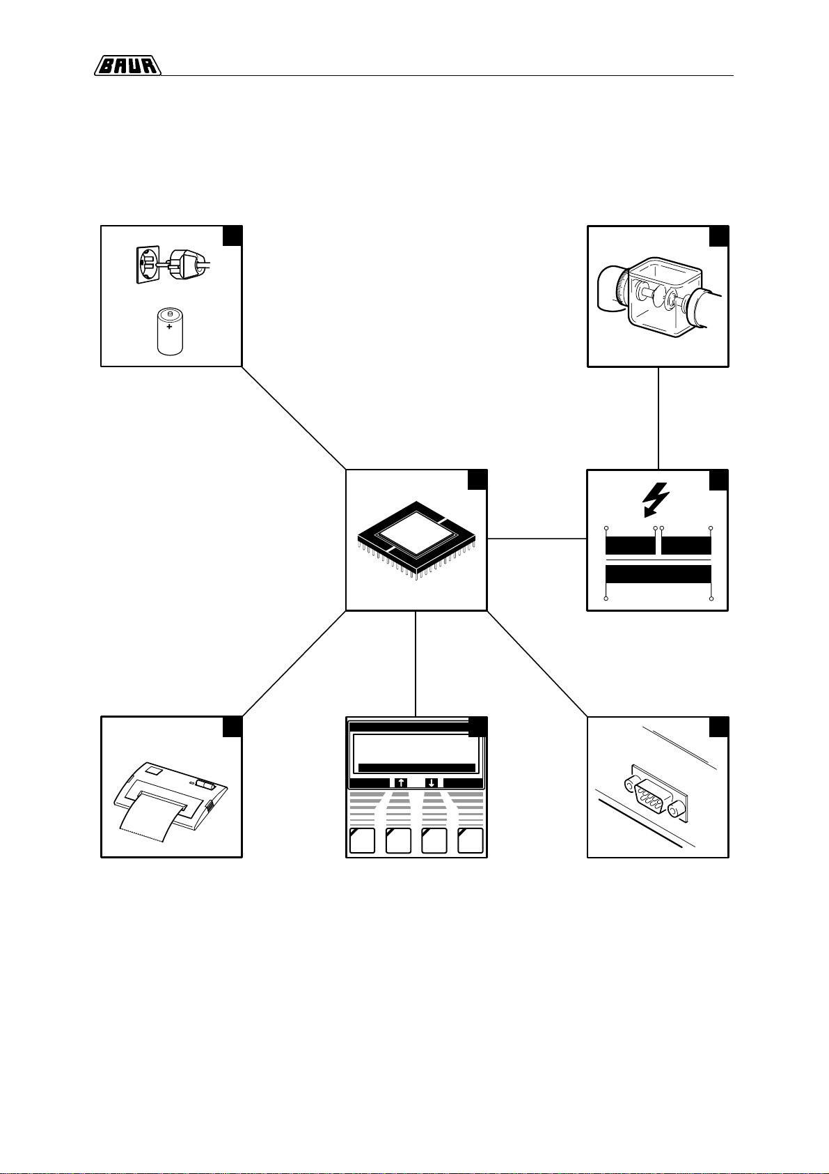
1.2 Construction / Principle
RETURN ENTER
MENU
STANDARD
INSTRUMENT SETTING
SINGLE TEST
1
6
5
3
24
EXTRA
7
CPU
Power Supply
High-voltage
Transformer
Control Unit
Control Panel RS232 Interface
bidirectional
Plain Paper Printer
(option)
Test Vessel and
Electrodes

1-4
Product Information
1 Power supply
- Mains operation (100 ... 240 V / 50/60 Hz) possible
via mains cable, even if battery is discharged.
With mains operation this symbol appears in the
upper right corner of any menu:
- Battery operation via internal and rechargable battery
(2 x 6V / 6.5Ah).
With connected mains cable battery charging
happens even with switched off unit.
2 Control unit
Coordinates all unit functions according to the
selected and actual menu.
3 Control panel
For selecting the desired menus.
4 High-voltage transformer
For generating the test voltage (max. 75 kV).
5 Test vessel and electrodes
Individually configurable depending on test standard.
Temperature acquisition of the insulating liquid via
sensor.
6 Plain-paper printer (option)
Reports test data automatically.
7 Interface RS232
Bidirectional interface on the rear of the unit for data
communication with a PC.

1-5
Product Information
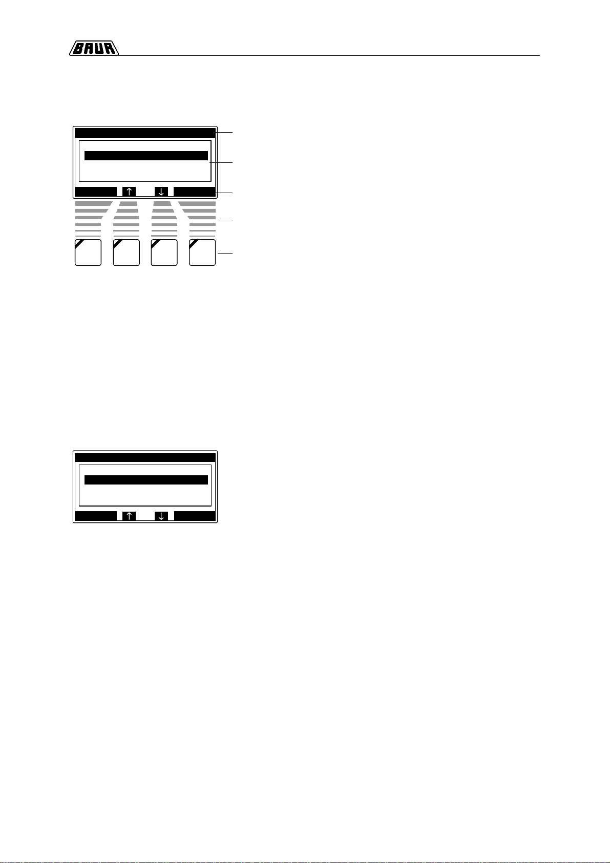
1.3 Function and control elements
3
2
5
6, 7
1
9
8
4
10

1-6
Product Information
1Gripping strip for opening/closing the protective
hood.
2Protective hood with self-acting mechanical locking
mechanism (double interlock switch - forced contact).
For highest operational safety!
3Test vessel with electrodes - available for all current
standards. Quickly removable test vessel for easy
cleaning, with a built-in vernier for exact setting of
electrode spacing.
4Easy-to-clean oil pan.
Suitable for cleaning with petroleum ether.
5Carrying handle (option) and shoulder strap - for
easy and simple mobile use.
6Built-in rechargeable battery - for mains independent
operation.
Integrated power supply unit for controlled battery
charging, even during a test.
7Bidirectional RS232 interface - for data
communication with a PC.
8Folding front panel - switches the DPA unit on/off
automatically.
9Built-in plain paper printer - for automatic reporting of
test data and test conditions (option).
10Control panel with self-explanatory menu-guiding.
Product Information
1-7
Product Information
Features:
- backlit dot matrix graphic display
- self-explanatory menu-guiding
- keys which can be activated and active menu
functions are highlighted with a black bar
INSTRUMENT SETTING
- CONTRAST: setting of display contrast
- LANGUAGES: selection of desired language:
GERMAN, ENGLISH, FRENCH,
SPANISH
- PRINTER: Disabling of the integrated printer is
possible
- RS232 INFO: Information to the interface
configuration RS232 for:
- service-mode
- cablibration-mode
- remote control
(with BAUR PC software)
- DATE: setting of actual date
- TIME: setting of actual time
Product Information
control keys
control keys assigned
display of functions to be activated
menu window
actual menu
RETURN ENTER
STANDARD
ASTM
ASTM
BS
CEI
D 877/87
D 1816/84
5874/80
10-1/73
1.4 Control panel
1.5 Menu overview
RETURN ENTER
MENU
STANDARD
INSTRUMENT SETTING
SINGLE TEST
EXTRA

1-8
Product Information
STANDARD
- 13 pre-programmed test standards are available:
ASTM D 1816/84 ASTM D 877/87
BS 5874/80 CEI 10-1/73
CSSR RVHP/85 IEC 156/95
IRAM 2341/72 JIS C2101/78
PN 77/ED4408 SEV 3141/69
UNE 21 309/89 UTE ✳60
VDE 0370/78
- Additionally in the submenu DEFINE TEST CYCLE
5 customer-specific test sequences are freely
programmable.
TEST CYCLE 1
TEST CYCLE 2
TEST CYCLE 3
TEST CYCLE 4
TEST CYCLE 5
SINGLE TEST
- Start of a single test
- Voltage rate of rise adjustable
(0.5 - 1 - 2 - 3 - 5 kV/s)
EXTRA
- BATTERY: Load status of rechargeable battery
and no. of further possible
breakdowns until recharge
- REPORT NO.: Input of a max. 12-digit report number
- ELECTRODES CLEAN.:
24 cleaning breakdowns are carried
out (when using new electrodes the
first time)
- DPA TEST: Menu item for high voltage testing
with calibrator KA 75.
- INFO: No. of software version.
Indication of date of the last
calibration (calibration of DPA unit
should be carried out once a year)
RETURN ENTER
MENU
STANDARD
INSTRUMENT SETTING
SINGLE TEST
EXTRA
MENU START
SINGLE TEST
2.0 kV/s
2.5 mm
RETURN ENTER
EXTRA
REPORT NR.
BATTERY
ELEKTRODES CLEAN.
DPA TEST
1-9
Product Information
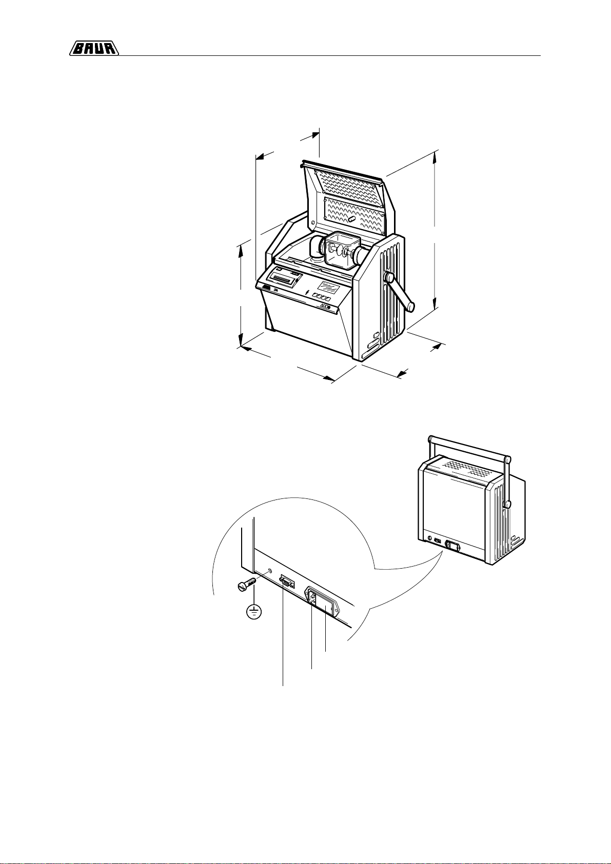
1.6 Technical data
DPA main dimensions
Dimensions in mm
T 4 A / fuse
90 . . . 264 V AC / mains supply
RS232 bidirectional / 9 pin Sub D
360
345
405 275
554
M6
connection
protective earthing
DPA interfaces

1-10
Product Information
Product Information
Power supply 100 ... 240 V (50 / 60 Hz)
Power consumption approx. 120 VA
Internal, rechargeable battery (option) 2 x 6 V / 6.5 Ahrs
Output voltage, dielectric strength test 0 ... 75 kVrms symmetric
For insulating liquids with tan dvalues < 4.5 or specific resistance r > 30 MWm
Voltage rate of rise 0.5 / 1 / 2 / 3 / 5 kV/s
Switch off current 4 mA
Switch-off time on breakdown £1 ms
Error message Real Breakdown Monitoring (RBM) detects actual flash over
Internal temperature acquisition of oil sample 0 - 99C/+32F...+120F
Temperature resolution 1C/1.8F
Display Back lit, 160 x 80 dot matrix LCD
Voltage indication digital 0 - 75 kV ± 1 kV
Resolution (displayed) 0.1 kV
Languages German, English, French, Spanish, ask for other languages
Interface bidirectional RS 232; 9600 Baud; 8 Bit
1 stopbit; no parity
9 pin sub D
Printer (option) matrix printer, 24 char.
57 mm / 2 1/4" plain paper
Operating temperature 0C ... +45C/+32F...+113F
Storage temperature - 20C ... +55C/-4F...+131F
Relative humidity £90 %
Dimensions 405 x 345 x 275 mm / 16" x 13 1/2" x 10 3/4"
Weight without battery 18.7 kg / 43.6 lbs
with battery (option) 21 kg / 49 lbs
Designed and built acc. to the following standards: IEC 1010,
EN 61010-1,
VDE 0411 Part 100

1-11
Product Information
1.7 RBM switching off
RBM is an electronic monitoring of the kV indication
which controls the measuring process at breakdown.
RBM monitors the linearity of voltage rate of rise within
a specified tolerance range.
RBM
Real Breakdown Monitoring
CONT.
WARNING 8
RBM SWITCHING OFF
IS ACTIVATED!
With key CONT. jump back to the actual menu.
Indication at
RBM switching off
- air breakdowns
- insulating liquid too low-resistive (eg with water)
- insulating liquid to be tested does not correspond
with the following specifications:
insulating liquid with tan dvalues < 4.5 resp. specific
resistance r > 30 MWm
Causes of RBM switching off
Condition for RBM Calibrated DPA 75 unit.
Calibration of the DPA 75 unit should be carried out
once per year.
With RBM switching off the test cycle is canceled
automatically. On the display appears:

1-12
Product Information
○○○○○○○○○○○○○○○○○○○○○○○○○○○○○○○○○○○○○○
○○○ ○○○○○○○○○○○○○○○○○○○○○○○○○○○○○○○○○○○
○○○○○○○○○○○○○○○○○○○○○○○○○○○○○○○○○○○○○○
○○○○○○○○○○○○○○○○○○○○○○○○○○○○○○○○○○○○○○
○○○○○○○○○○○○○○○○○○○○○○○○○○○○○○○○○○○○○○
○○○ ○○○○○○○○○○○○○○○○○○○○○○○○○○○○○○○○○○○
○○○○○○○○○○○○○○○○○○○○○○○○○○○○○○○○○○○○○○
○○○○○○○○○○○○○○○○○○○○○○○○○○○○○○○○○○○○○○
○○○ ○○○○○○○○○○○○○○○○○○○○○○○○○○○○○○○○○○○
○○○○○○○○○○○○○○○○○○○○○○○○○○○○○○○○○○○○○○
○○○ ○○○○○○○○○○○○○○○○○○○○○○○○○○○○○○○○○○○
○○○ ○○○○○○○○○○○○○○○○○○○○○○○○○○○○○○○○○○○
○○○ ○○○○○○○○○○○○○○○○○○○○○○○○○○○○○○○○○○○
○○○○○○○○○○○○○○○○○○○○○○○○○○○○○○○○○○○○○○
○○○ ○○○○○○○○○○○○○○○○○○○○○○○○○○○○○○○○○○○
○○○ ○○○○○○○○○○○○○○○○○○○○○○○○○○○○○○○○○○○
○○○○○○○○○○○○○○○○○○○○○○○○○○○○○○○○○○○○○○
○○○ ○○○○○○○○○○○○○○○○○○○○○○○○○○○○○○○○○○○
○○○○○○○○○○○○○○○○○○○○○○○○○○○○○○○○○○○○○○
○○○ ○○○○○○○○○○○○○○○○○○○○○○○○○○○○○○○○○○○
○○○ ○○○○○○○○○○○○○○○○○○○○○○○○○○○○○○○○○○○
○○○ ○○○○○○○○○○○○○○○○○○○○○○○○○○○○○○○○○○○
Notes
Table of contents
Other Baur Test Equipment manuals


